EP0082170B1 - Procede et appareil de mise en balles - Google Patents
Procede et appareil de mise en balles Download PDFInfo
- Publication number
- EP0082170B1 EP0082170B1 EP82901966A EP82901966A EP0082170B1 EP 0082170 B1 EP0082170 B1 EP 0082170B1 EP 82901966 A EP82901966 A EP 82901966A EP 82901966 A EP82901966 A EP 82901966A EP 0082170 B1 EP0082170 B1 EP 0082170B1
- Authority
- EP
- European Patent Office
- Prior art keywords
- bale chamber
- inlet end
- feed
- crop material
- mat
- Prior art date
- Legal status (The legal status is an assumption and is not a legal conclusion. Google has not performed a legal analysis and makes no representation as to the accuracy of the status listed.)
- Expired
Links
Images



Classifications
-
- A—HUMAN NECESSITIES
- A01—AGRICULTURE; FORESTRY; ANIMAL HUSBANDRY; HUNTING; TRAPPING; FISHING
- A01F—PROCESSING OF HARVESTED PRODUCE; HAY OR STRAW PRESSES; DEVICES FOR STORING AGRICULTURAL OR HORTICULTURAL PRODUCE
- A01F15/00—Baling presses for straw, hay or the like
Definitions
- the present invention relates generally to a method ' and apparatus for forming fibrous material into bales, and more particularly to a crop baler of the type adapted to be propelled forwardly across a field, and the method practiced by such a baler.
- balers are well known today.
- the most commonly used field baler of today forms a rectangular bale by picking up crop material by means of a crop pickup, transferring the crop material laterally by means of packer fingers to the forward end of the bale chamber, and then compressing the crop material into a bale by means of a plunger which conventionally operates in the range of 50 to 100 strokes per minute.
- the bales are then tied off into lengths which generally vary from (3 to 4 feet) 90 to 120 centimetres length.
- Most of these bales have a (14 or 16 inch) 35 or 40 centimetres by (18 inch) 45 centimetres cross section and can be manually handled after baling.
- bales (16 x 23 inch) 40 x 58 centimetres are more suitable for machine handling.
- large numbers of automatic balers of this type have been produced and hay baled by machines of this type are of good quality and are suitable for long term storage.
- baler pioneered by Vermeer. and others, and typically illustrated in U.S. Patent No. 3,722,197 produces a large round bale of approximately (4 to 5 feet) 120 to 152 centimetres in width and having a similar diameter. Such round bales have good field storage characteristics, but are difficult to handle and are also difficult to stack in enclosed areas. In addition, the baler must be stopped when discharging a bale, and care must be taken when working on a hillside to ensure that the bale does not start rolling down the hill.
- balers In addition to the various commercial types of balers referred to above, other prior art forms of balers have been suggested. One such type is shown in the Molitorisz U.S. Patent 4,175,487. This form of baler utilizes cooperating belts and rollers which are oscillated across the inlet end of the bale chamber.
- Sets of upper and lower endless belts engage opposed surfaces of a mat crop there between and convey this continuously to the inlet end of the bale chamber.
- the rear ends of the belts adjacent the inlet end are supported on respective upper and lower sets of pulleys that are interspaced coaxially with sets of rollers, and each of these upper and lower sets of rollers is connected to a respective upper or lower set of wrapping belts on which they wrap and unwrap as they are oscillated across the inlet end of the bale chamber.
- the wrapping belts thereby serve to close the inlet end of the bale chamber above and below the rollers so as to retain crop therein as the mat crop is formed into successive folded layers by said oscillating movement of the belts and rollers across the inlet end of the bale chamber.
- DE-139340 discloses a similar baler to that of U.S. 4175 487 comprising conveyor belts that feed a mat crop to the inlet end of the bale chamber and roller mechanism that is oscillated across the inlet end to form the mat into successive folded layers within the bale chamber.
- the rollers instead of the rollers being connected to wrapping belts, they are connected to wall members that serve the same function of closing the inlet either side of the rollers. The rollers are not positively driven but simply rotate in engagement with the crop mat.
- the pulleys at the rear of the conveyor belts are not coaxial with the rollers, but instead have parallel axes adjacent one another, and the gap between the rollers is made greater than that .between the pulleys so that the crop mat engages only the upper or lower set of rollers as it is fed into the bale chamber.
- the invention consists in providing a bale chamber having a forward inlet end; providing feeding means at the inlet end of the bale chamber to feed a mat of crop material in a rearward direction into the bale chamber, the feeding means having spaced-apart feed surfaces simultaneously in engagement with opposed surfaces of the rearwardly conveyed mat of crop material; moving the feeding means and inlet end of the bale chamber to and fro relative to one another to form successive layers of folded crop material within the bale chamber; and characterised in that the feed surfaces have an effective one-way aggressive action and are positively driven so that only one surface of said mat is fed rearwards by one of the engaging feed surfaces as the mat is fed in a first direction within the bale chamber to form one layer of folded crop material, and only the other surface of said mat is fed rearwards by the other of the engaging feed surfaces as the mat is fed in a second direction within the bale chamberto form a successive layer of folded crop material.
- the feed surfaces comprise saw tooth like elements secured to a pair of relatively closely spaced parallel rollers which are in turn carried by a common support.
- a mechanism is provided to move the rollers back and forth across the inlet end of the baler.
- drive means are provided which cause the rollers to rotate in a common first direction when they are moved in one direction across the inlet end of the bale chamber, and to rotate in the opposite direction when they are moved in another direction across the inlet end of the bale chamber.
- the drive means can be either a rack and pinions, or alternatively a chain and sprockets.
- the rotational speed of the rollers is such that the peripheral speed of the saw tooth like elements is substantially the same as the speed of movement of the rollers across the inlet end of the bale chamber whereby the sawtooth like elements will not tend to tear the folded layers of material within the bale chamber.
- Hay checks are provided at opposite sides of the inlet end of the bale chamber and successively retain the crop material within the bale chamber.
- the feed surfaces comprise sawtooth like elements carried by adjacent opposed surfaces of upper and tower flights which pass over a pair of parallel roll structures.
- One end of each of the opposed flights is secured adjacent an associated side of the inlet end of the bale chamber.
- the other ends of the 'opposed flights are interconnected to each other by intermediate cable means which pass over intermediate idlers.
- the roll structures are reciprocated back and forth across the inlet end of the bale chamber, and this reciprocal movement causes the opposed surfaces to move in opposite directions. A mat of material is conveyed to the opposed surfaces and reciprocal movement of the surfaces will cause the mat to be fed into the inlet end of the bale chamber.
- the ba ler of this invention is indicated generally at 10.
- the baler includes a frame 12 to which are secured ground engaging wheels 14.
- Mounted above the frame 12 is a bale chamber 16.
- a knotter mechanism, indicated generally at 18, is mounted on top of the bale chamber.
- a forwardly extending tongue 20 is secured to the baler at a location spaced behind the knotter mechanism and extends forwardty, the forward end of the tongue being secured to the drawbar 22 of a tractor indicated generally at 24.
- Conveying means, indicated generally at 26 and feeding means, indicated generally at 28, are mounted forwardly of the bale chamber 16, the feeding means extending between the conveying means and the bale chamber.
- the bale chamber has a forward inlet end 30, and a generally conventional tension rail mechanism 31.
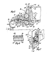
- the feeding means 28 includes a pair of spaced apart adjacent parallel roll structures 32 disposed in front of the inlet end 30.
- Each of the roll structures 32 includes a cylindrical section 34, right and left end plates 36 (only the left end plate being shown in Fig. 7) and outwardly projecting right and left stub shafts 38.
- Mounted on the periphery of each tubular portion 34 are plurality of saw tooth like feed elements 40. As illustrated in Figs.
- each of the saw tooth like elements has a sharply inclined leading surface 42 and a slightly inclined trailing surface 44.
- Figs. 2 and 6 there are a plurality of axially spaced apart arrays of saw tooth like feed elements extending across the width of each of the rollers, the saw tooth like feed elements in each array lying in a common plane.
- the shafts 38 are coaxial with the cylindrical sections 34.
- Right and left hand moving means 46 are provided to move the roll structures 32 back and forth across the inlet end of the bale chamber (only the left hand moving means 46 being shown in Fig. 7).
- right and left hand common supports 48 are provided in which the ends of the stub shafts 38 are journalled, the right hand stub shafts being journalled in a right hand common support (not shown) and the left hand stub shafts 38 being journalled in a left hand common support 48 (Fig. 7).
- Each of the moving means may be in the form of an extensible and retractable hydraulic cylinder assembly 50, the rod end 52 being secured to a portion of the common support 48, and the anchor end being secured to a bracket 54 supported on forwardly extending sheet metal structure or frame 56 which is in turn interconnected with a side of the bale chamber 16.
- the feeding means lies between right and left hand sheet metal structures 56.
- each of the sheet metal structures 56 is provided with a vertically extending slot 58.
- Pulley like members 60 are journalled about the stub shafts 38, the pulley like members engaging the vertically extending side walls of the slots 58.
- drive means indicated generally at 61 are provided.
- Fig. 7 one form of drive means is illustrated, this form including a rack 62 and pinions 64 secured to the stub shafts 38 in any conventional manner.
- a rack 62 and pinions 64 secured to the stub shafts 38 in any conventional manner.
- This form of drive means includes a chain 66, sprockets 68 secured to the ends of the stub shafts 38, and an idler sprocket 70 journalled for rotation on shaft 72 which is in turn secured to the common support 48.
- the common support 48 shown in Fig. 8 has a different configuration than that shown in Fig. 7, it forms the identical function of maintaining the spacing between the rolls 32 while in turn permitting their movement back and forth across the inlet end of the bale chamber when the cylinder assemblies 50 are extended or retracted).
- the ends of the chain 66 are secured by suitable fasteners 74 to the associated sheet metal structure 56.
- the conveying means include -a generally conventional crop pickup, indicated generally at 76, and a structure 77 including a feed surface 78 extending between the crop pickup and the feeding means 28.
- a feed surface 78 As the baler 10 is propelled forwardly across a field a mat of material will be picked up from the ground by the crop pickup 76 and will be conveyed rearwardly across the feed surface 78 to the feeding means 28.
- the feed surface 78 is provided with a plurality of slots 80 through which packer tines 82 extend.
- the crop pickup 76 is suitably interconnected with the frame 12 by a subframe 84, only a portion of which is illustrated in Figs. 3-5.
- a transversely extending shaft 86 is journalled within brackets 88 which are in turn secured to the forward end of the subframe 84.
- the rear ends of downwardly and forwardly extending rock arms 90 are journalled about shaft 86, the forward end of the rock arms in turn supporting the pickup mechanism.
- the pickup mechanism 76 can follow ground contours as the rock arms 90 are free to pivot about the shaft 86.
- the platform 78 is in turn secured at its forward end to plate means 92 which are also journalled about the shaft 86.
- Rear side extensions of the feed surface 78 are in turn journalled to arms 94 which are in turn journalled on the stub shafts 38 for the lower roller 32, the arms being disposed between the end plates 36 and the pulley like members 60.
- each of the packer tines or forks 82 is in turn supported by a lower link 95 and an upper crank arm 96.
- each of the lower links 95 is pivotally secured at its rearward end to the lower end of a packer tine 82 and at its forward end to the plate means 92.
- one end of each of the crank arms 96 is pivotally secured to a packer tine 82 and the other end is secured to a rotatable shaft 97.
- the shaft 97 is rotated (in any conventional manner) in the direction indicated by arrow 98 which will cause the crank arms 96 to rotate in a clockwise direction when viewed from the left hand side of the machine.
- arrow 98 which will cause the crank arms 96 to rotate in a clockwise direction when viewed from the left hand side of the machine.
- the packer tines will convey material deposited upon the feed surface 78 in a rearward direction to force the material into the bite or nip of the parallel spaced apart rollers 32, the tips of the packer tines generally following the orbital path indicated at 99.
- Figs. 2-8 The operation of the embodiment illustrated in Figs. 2-8 is as follows: During baling, as the hay baler is propelled forwardly over the surface of the ground by the farm tractor 24 or the like, the conveying means 26 will pick up a mat of fibrous crop material and convey it in a rearward direction initially over the crop pickup 76 and then over the feed surface 78. During baling it should be appreciated that the crop pickup will be rotated in a clockwise direction as viewed from the left hand side of the machine, that the ends of the packer tines 82 will be moved in a clockwise orbital direction, and that simultaneously the rollers will be oscillated upwardly and downwardly across the inlet end of the bale chamber.
- the saw tooth like elements carried by the rollers will feed more aggressively in one direction than the other.
- opposed surfaces of the mat are simultaneously engaged by the saw tooth like elements.
- the closely spaced apart adjacent feed surfaces will thus tend to feed the mat of crop material in a rearward direction.
- the sharply inclined leading surface of each of the saw tooth like elements will more aggressively feed the mat of fibrous crop material than the slightly inclined trailing surfaces.
- the lower roller will tend to feed the crop material into the bale chamber through the action of the saw tooth like elements adjacent the upper roller 32, and simultaneously, those saw tooth like elements adjacent the face of the layer of crop material being folded within the bale chamber will tend to compress said layer.
- the rollers 32 both feed and compress the mat of crop material into the bale chamber.
- the peripheral speed of the rollers corresponds to the vertical speed of the rollers.
- check means As can be seen from inspection of Figs. 3, 4 and 5, as the rollers move back and forth across the inlet end of the bale chamber a portion of the fed crop material will not be confined by the rollers. Thus, when the rollers are in their upper position, as illustrated in Fig. 4, the lower surface of the successive layers which have been folded into the bale chamber are exposed. Similarly, when the rollers are in their lowermost position, as illustrated in Fig. 5, the upper surface is exposed. Therefore, it is essential that check means be provided to prevent fibrous crop material from springing out of the inlet end of the bale forming chamber as there is a certain amount of natural resiliency within the crop material. Thus, check means, indicated generally at 100, are provided for this purpose.
- each of the check means includes right and left hand pivoted members 102 which are interconnected with each other by a forwardly disposed transversely extending shaft or member 104.
- a plurality of retainer means 106 are mounted on each shaft 104, and in addition engaging members 108 are mounted in the outer ends of each shaft.
- the upper and lower check means are spring biased towards each other by a tension spring. 110.
- the operation of the check means can be best appreciated from an inspection of Figs. 4 and 5.
- the cylindrical section 34 engages the upper engaging members 108 and continued upward movement of the pair of parallel rollers will cause the retaining means 106 to uncover the upper edge of the last folded layer of crop material.
- the spring 110 will be tensioned.
- the spring 110 will bring the upper check means back into its checking position illustrated in Fig. 5, and also in Fig. 6, and continued downward movement will cause the lower cylindrical section 34 to engage the lower engaging member 108 to cause the lower retaining means 106 to uncover the lower edge of the face of the bale being formed within the bale chamber.
- the top of the bale chamber limits the inward movement of the check means 100. It has been found that it is desirable that the retainers 106 be spaced closely adjacent the saw tooth like elements 40 to insure that the checks will properly move into their retaining position. This relationship is illustrated in Fig. 6.
- the bale after being formed is tied off in a manner not material to the present invention.
- the embodiment shown Figs. 9 and 10 utilizes a somewhat different form of feeding and compressing means 28.
- the saw tooth like elements 40 are carried by chain means which in turn pass over rollers in the form of a plurality of spaced apart sprockets 114. While the sprockets 114 could be supported on transversely extending shafts, in the embodiment illustrated they are supported on the cylindrical section 34 of a roll structure 32 similar to the roller illustrated in Figs. 2-8, the cylindrical section 34 being carried by stub shafts 38.
- the chain means, indicated generally at 116 thus includes opposed spaced apart upper and lower flights 118, 120, respectively, to which the saw tooth like elements are secured.
- the chain means also includes intermediate cable mean ' s 122.
- each of the opposed flights is formed of a plurality of spaced apart conveyor chains 118, 120, the intermediate portions of the flights 118, 120 being supported by the pair of forward idlers 126, 128 and by adjacent portions of the pair of rollers 32.
- the intermediate cable is in turn journalled over upper and lower idlers illustrated by upper sheave 130 and lower sheave 132.
- the intermediate cable means 122 in order not to interfere with the fed mat of crop material, which is confined between the upper and lower conveyor flights 118, 120, is in fact disposed to one side of the flights. To this end, it is necessary to provide a transversely extending member 134 to which each of said spaced apart conveyor chains is secured, the intermediate cable means 122 being secured to the ends of the transversely extending member 134.
- stub shafts 38 are carried by common supports 48 which are reciprocated upwardly and downwardly by means of hydraulic cylinders 50 or the like.
- the lower flight 120 will have effective rearward movement while the upper flight will have an effective forward movement.
- the saw tooth like elements are more aggressive when being moved in the rearward direction towards the inlet end of the bale chamber, crop material. confined between the feeding and compressing flights 118 and 120 will be conveyed in a rearward direction.
- the cable means 122 ensures that take up movement of one flight, for example flight 120 when roller 114 is being moved upwardly, will cause payout movement of the upper flight 118.
- the idlers 126 and 130 should be spaced apart a distance at least equal to the stroke of the rollers to allow the member 134 to move freely. Also, it is desirable that the idlers 126, 128 be equally spaced away from the centerline 144 of the bale chamber.
- the upper position of the rollers 32 is shown in full lines in Fig. 9 while the lower position of the rollers is shown in broken lines.
- Fig. 9 the conveying means is illustrated only by a crop pickup 76 pivoted to cross shaft 86 which is in turn carried by the frame of the baler.
- a feed surface and feed fingers 78, 82 which may be in the form illustrated in Figs. 2-5.
- the feeding means it is necessary to provide the feeding means with a feed surface 138 consisting of two telescoping elements 140, 142, the first being pivoted to shaft 86 and the other to stub shafts 38.
- the feed surface 138 prevents crop material from falling to the ground.
Landscapes
- Life Sciences & Earth Sciences (AREA)
- Environmental Sciences (AREA)
- Storage Of Harvested Produce (AREA)
- Preliminary Treatment Of Fibers (AREA)
Claims (18)
Applications Claiming Priority (2)
| Application Number | Priority Date | Filing Date | Title |
|---|---|---|---|
| US276448 | 1981-06-22 | ||
| US06/276,448 US4803832A (en) | 1981-06-22 | 1981-06-22 | Method and apparatus for forming bales |
Publications (2)
| Publication Number | Publication Date |
|---|---|
| EP0082170A1 EP0082170A1 (fr) | 1983-06-29 |
| EP0082170B1 true EP0082170B1 (fr) | 1986-12-10 |
Family
ID=23056703
Family Applications (1)
| Application Number | Title | Priority Date | Filing Date |
|---|---|---|---|
| EP82901966A Expired EP0082170B1 (fr) | 1981-06-22 | 1982-06-14 | Procede et appareil de mise en balles |
Country Status (8)
| Country | Link |
|---|---|
| US (1) | US4803832A (fr) |
| EP (1) | EP0082170B1 (fr) |
| JP (1) | JPS58500971A (fr) |
| CA (1) | CA1269884A (fr) |
| DE (1) | DE3274618D1 (fr) |
| IT (1) | IT1152990B (fr) |
| WO (1) | WO1983000002A1 (fr) |
| ZA (1) | ZA824277B (fr) |
Cited By (1)
| Publication number | Priority date | Publication date | Assignee | Title |
|---|---|---|---|---|
| DE19821591C1 (de) * | 1998-05-14 | 1999-11-18 | Welger Geb | Fördereinrichtung, insbesondere für landwirtschaftliche Pressen |
Families Citing this family (27)
| Publication number | Priority date | Publication date | Assignee | Title |
|---|---|---|---|---|
| EP0117377B1 (fr) * | 1983-03-01 | 1988-06-08 | B.V. Multinorm | Dispositif de formation d'une balle de fourrage par pressage |
| FR2556412A1 (fr) * | 1983-12-12 | 1985-06-14 | Gen Electric | Procede et appareil pour degrader un combustible anti-brumisant |
| US4999987A (en) * | 1988-01-11 | 1991-03-19 | Karl Mengele & Sohne | Apparatus for harvesting of field-fodder |
| US5193449A (en) * | 1990-11-21 | 1993-03-16 | Ransom Woodbury S | Hay baler |
| DE9318117U1 (de) * | 1993-11-26 | 1994-12-22 | Gebrüder Welger GmbH & Co KG, 38304 Wolfenbüttel | Rundballenpresse |
| US5479766A (en) * | 1994-07-06 | 1996-01-02 | Ransom; Woodbury S. | Baling apparatus and method |
| US6032446A (en) * | 1998-04-06 | 2000-03-07 | Deere & Company | Densification method and apparatus for harvested cotton or other similar fibrous material |
| US7024839B2 (en) * | 2001-10-11 | 2006-04-11 | Paul Wingert | Agricultural bagger with upper tunnel compaction and chute agitation |
| CA2446267C (fr) * | 2002-10-24 | 2007-07-03 | Deere & Company | Machine de recuperation de recolte |
| DE10313492B4 (de) * | 2003-03-26 | 2005-06-23 | Maschinenfabrik Bernard Krone Gmbh | Vorrichtung und Verfahren zur Erfassung und Regelung der Ballenlänge |
| US7266936B2 (en) * | 2003-05-15 | 2007-09-11 | Wingert Paul R | Agricultural bagger with shielded hopper agitation and method |
| US7127985B2 (en) * | 2003-09-11 | 2006-10-31 | Standlee Michael G | Method and apparatus for creating consumer friendly hay bales |
| US20060168913A1 (en) | 2005-01-31 | 2006-08-03 | Wingert Paul R | Agricultural bagger with dual rotor and/or variable-taper tunnel |
| DE102007031211B4 (de) | 2007-07-04 | 2014-05-22 | Claas Selbstfahrende Erntemaschinen Gmbh | Ballenpresse |
| US20090241480A1 (en) * | 2008-04-01 | 2009-10-01 | Src Innovations, Llc | Mobile bagging machine rotor assembly and transmission |
| US8353148B2 (en) * | 2010-02-10 | 2013-01-15 | Deere & Company | Method of crop pickup floating |
| US8820040B2 (en) | 2011-07-01 | 2014-09-02 | Cnh Industrial America Llc | Compression rolls on baler pick up |
| US9173347B2 (en) * | 2011-07-01 | 2015-11-03 | Cnh Industrial America Llc | Balers and methods for forming high density bales |
| US8800255B2 (en) * | 2011-07-01 | 2014-08-12 | Cnh Industrial America Llc | Arrangement and control of precompression rolls in balers |
| US8371097B1 (en) * | 2011-09-26 | 2013-02-12 | Cnh America Llc | Baler gathering wheel height adjustment |
| CA2831765A1 (fr) * | 2012-11-05 | 2014-05-05 | Charles Siebenga | Ramasseuse-presse a balles rectangulaires continue |
| CN107074452B (zh) | 2014-07-23 | 2020-01-21 | 凯斯纽荷兰(中国)管理有限公司 | 用于农业器具的进给系统 |
| US9591807B1 (en) | 2016-03-10 | 2017-03-14 | Charles Siebenga | Continuous square baler |
| US11382275B2 (en) | 2016-08-31 | 2022-07-12 | Tube-Line Manufacturing Limited | Continuous round baler accumulation chamber |
| RU2657469C1 (ru) * | 2017-07-06 | 2018-06-14 | Федеральное государственное бюджетное научное учреждение Федеральный научный агроинженерный центр ВИМ (ФГБНУ ФНАЦ ВИМ) | Автоматизированный рулонный агрегат с обеззараживанием стебельчатых кормов |
| WO2021011773A1 (fr) * | 2019-07-16 | 2021-01-21 | Cnh Industrial Canada, Ltd. | Système d'enveloppement de balles |
| CN114303654B (zh) * | 2021-12-20 | 2023-07-21 | 铁建重工新疆有限公司 | 一种拨草预压装置及喂入设备 |
Family Cites Families (14)
| Publication number | Priority date | Publication date | Assignee | Title |
|---|---|---|---|---|
| DE139340C (fr) * | ||||
| US2731782A (en) * | 1956-01-24 | mason | ||
| AT116580B (fr) * | ||||
| US879639A (en) * | 1907-10-01 | 1908-02-18 | Robert E Haynes | Cotton-press. |
| US1135146A (en) * | 1914-04-13 | 1915-04-13 | W W Wagg | Conveyer for binding-machines. |
| US1496363A (en) * | 1921-06-11 | 1924-06-03 | Bonnafoux Paul | Automatic hay baler |
| US1496364A (en) * | 1921-06-14 | 1924-06-03 | Bonnafoux Paul | Self-feeding hay press |
| DE2457395A1 (de) * | 1974-12-05 | 1976-06-10 | Gerhard Dr Ing Maerz | Aufsammel-ballenpresse |
| US4086749A (en) * | 1976-08-16 | 1978-05-02 | Sperry Rand Corporation | Adjustable width row crop header |
| US4270446A (en) * | 1978-07-12 | 1981-06-02 | Joseph Molitorisz | Bale forming apparatus |
| US4175487A (en) * | 1978-07-12 | 1979-11-27 | Joseph Molitorisz | Bale forming apparatus |
| GB2042415B (en) * | 1979-02-28 | 1983-01-06 | Claas Ohg | Agricultural baler |
| ZA804589B (en) * | 1979-08-02 | 1981-12-30 | Pressmora Nominees Pty Ltd | Impoved bale-forming press |
| US4273034A (en) * | 1980-01-23 | 1981-06-16 | Joseph Molitorisz | Bale forming apparatus |
-
1981
- 1981-06-22 US US06/276,448 patent/US4803832A/en not_active Expired - Fee Related
-
1982
- 1982-06-14 WO PCT/EP1982/000124 patent/WO1983000002A1/fr not_active Ceased
- 1982-06-14 JP JP57502059A patent/JPS58500971A/ja active Pending
- 1982-06-14 EP EP82901966A patent/EP0082170B1/fr not_active Expired
- 1982-06-14 DE DE8282901966T patent/DE3274618D1/de not_active Expired
- 1982-06-17 ZA ZA824277A patent/ZA824277B/xx unknown
- 1982-06-21 CA CA000405604A patent/CA1269884A/fr not_active Expired - Lifetime
- 1982-06-22 IT IT21984/82A patent/IT1152990B/it active
Cited By (1)
| Publication number | Priority date | Publication date | Assignee | Title |
|---|---|---|---|---|
| DE19821591C1 (de) * | 1998-05-14 | 1999-11-18 | Welger Geb | Fördereinrichtung, insbesondere für landwirtschaftliche Pressen |
Also Published As
| Publication number | Publication date |
|---|---|
| JPS58500971A (ja) | 1983-06-23 |
| US4803832A (en) | 1989-02-14 |
| WO1983000002A1 (fr) | 1983-01-06 |
| IT1152990B (it) | 1987-01-14 |
| IT8221984A0 (it) | 1982-06-22 |
| DE3274618D1 (en) | 1987-01-22 |
| CA1269884A (fr) | 1990-06-05 |
| EP0082170A1 (fr) | 1983-06-29 |
| ZA824277B (en) | 1983-04-27 |
Similar Documents
| Publication | Publication Date | Title |
|---|---|---|
| EP0082170B1 (fr) | Procede et appareil de mise en balles | |
| US4870812A (en) | Round baler with variable bale chamber | |
| EP0337006B1 (fr) | Machine pour former des balles cylindriques de fourrage | |
| US5595055A (en) | Pickup apparatus for a round baler | |
| US5191833A (en) | Roll stripping apparatus for round baler | |
| US8037814B1 (en) | Method of staggering belts in a round baler | |
| US4169347A (en) | Belt-type baler for cylindrical bales | |
| CN110612809A (zh) | 一种自走式连续作业圆捆打捆机 | |
| EP0339730B1 (fr) | Presse à balles rondes avec chambre variable et ensemble presseur | |
| US4455930A (en) | Method and apparatus for delivering twine to a baler knotter | |
| EP0087432B1 (fr) | Presse a balles | |
| CA1071014A (fr) | Machine a former des bottes de foin | |
| US4644739A (en) | Agricultural baler | |
| US3848526A (en) | Hay roll forming machine | |
| EP0487232A2 (fr) | Presse à balles pour foin | |
| US4993217A (en) | Machine for forming cylindrical bales of crop | |
| EP0097180A4 (fr) | Systeme de communications a commande distribuee. | |
| US4424662A (en) | Drive apparatus for roll baling machine | |
| US4172355A (en) | Upper apron assembly | |
| EP0383076A1 (fr) | Machine pour former des balles rondes | |
| EP0086205B1 (fr) | Procede et dispositif permettant de fournir de la ficelle a un dispositif noueur de balles | |
| BE1004940A3 (nl) | Verrijdbare inrichting voor het oprapen en tot balen vormen van ten minste een zwad hoofdzakelijk parallelle stengels. | |
| US5327711A (en) | Baler feeding apparatus | |
| JPH026758Y2 (fr) | ||
| CA1187738A (fr) | Methode et appareil d'alimentation en corde pour lieuse de balles |
Legal Events
| Date | Code | Title | Description |
|---|---|---|---|
| PUAI | Public reference made under article 153(3) epc to a published international application that has entered the european phase |
Free format text: ORIGINAL CODE: 0009012 |
|
| 17P | Request for examination filed |
Effective date: 19830222 |
|
| AK | Designated contracting states |
Designated state(s): DE FR GB |
|
| GRAA | (expected) grant |
Free format text: ORIGINAL CODE: 0009210 |
|
| AK | Designated contracting states |
Kind code of ref document: B1 Designated state(s): DE FR GB |
|
| REF | Corresponds to: |
Ref document number: 3274618 Country of ref document: DE Date of ref document: 19870122 |
|
| ET | Fr: translation filed | ||
| PLBE | No opposition filed within time limit |
Free format text: ORIGINAL CODE: 0009261 |
|
| STAA | Information on the status of an ep patent application or granted ep patent |
Free format text: STATUS: NO OPPOSITION FILED WITHIN TIME LIMIT |
|
| 26N | No opposition filed | ||
| PGFP | Annual fee paid to national office [announced via postgrant information from national office to epo] |
Ref country code: GB Payment date: 19900529 Year of fee payment: 9 Ref country code: FR Payment date: 19900529 Year of fee payment: 9 |
|
| PGFP | Annual fee paid to national office [announced via postgrant information from national office to epo] |
Ref country code: DE Payment date: 19900605 Year of fee payment: 9 |
|
| PG25 | Lapsed in a contracting state [announced via postgrant information from national office to epo] |
Ref country code: GB Effective date: 19910614 |
|
| GBPC | Gb: european patent ceased through non-payment of renewal fee | ||
| PG25 | Lapsed in a contracting state [announced via postgrant information from national office to epo] |
Ref country code: FR Effective date: 19920228 |
|
| PG25 | Lapsed in a contracting state [announced via postgrant information from national office to epo] |
Ref country code: DE Effective date: 19920401 |
|
| REG | Reference to a national code |
Ref country code: FR Ref legal event code: ST |