EP0082178B1 - Instrument optique a image stabilisee - Google Patents
Instrument optique a image stabilisee Download PDFInfo
- Publication number
- EP0082178B1 EP0082178B1 EP82901993A EP82901993A EP0082178B1 EP 0082178 B1 EP0082178 B1 EP 0082178B1 EP 82901993 A EP82901993 A EP 82901993A EP 82901993 A EP82901993 A EP 82901993A EP 0082178 B1 EP0082178 B1 EP 0082178B1
- Authority
- EP
- European Patent Office
- Prior art keywords
- objective
- stabilized
- stabilization
- optical element
- optical
- Prior art date
- Legal status (The legal status is an assumption and is not a legal conclusion. Google has not performed a legal analysis and makes no representation as to the accuracy of the status listed.)
- Expired
Links
- 230000003287 optical effect Effects 0.000 title claims abstract description 46
- 230000006641 stabilisation Effects 0.000 claims description 57
- 238000011105 stabilization Methods 0.000 claims description 57
- 230000001133 acceleration Effects 0.000 claims 2
- 239000000725 suspension Substances 0.000 abstract 1
- 238000000034 method Methods 0.000 description 11
- 230000008901 benefit Effects 0.000 description 8
- 238000010276 construction Methods 0.000 description 7
- 230000000007 visual effect Effects 0.000 description 5
- 230000007246 mechanism Effects 0.000 description 4
- 230000004075 alteration Effects 0.000 description 3
- 230000004048 modification Effects 0.000 description 3
- 238000012986 modification Methods 0.000 description 3
- 230000000087 stabilizing effect Effects 0.000 description 3
- 230000005484 gravity Effects 0.000 description 2
- QNRATNLHPGXHMA-XZHTYLCXSA-N (r)-(6-ethoxyquinolin-4-yl)-[(2s,4s,5r)-5-ethyl-1-azabicyclo[2.2.2]octan-2-yl]methanol;hydrochloride Chemical compound Cl.C([C@H]([C@H](C1)CC)C2)CN1[C@@H]2[C@H](O)C1=CC=NC2=CC=C(OCC)C=C21 QNRATNLHPGXHMA-XZHTYLCXSA-N 0.000 description 1
- 241000735235 Ligustrum vulgare Species 0.000 description 1
- 230000008859 change Effects 0.000 description 1
- 238000013016 damping Methods 0.000 description 1
- 230000001419 dependent effect Effects 0.000 description 1
- 230000006866 deterioration Effects 0.000 description 1
- 230000002542 deteriorative effect Effects 0.000 description 1
- 230000001788 irregular Effects 0.000 description 1
- 230000010355 oscillation Effects 0.000 description 1
- 230000001681 protective effect Effects 0.000 description 1
Images


Classifications
-
- G—PHYSICS
- G02—OPTICS
- G02B—OPTICAL ELEMENTS, SYSTEMS OR APPARATUS
- G02B27/00—Optical systems or apparatus not provided for by any of the groups G02B1/00 - G02B26/00, G02B30/00
- G02B27/64—Imaging systems using optical elements for stabilisation of the lateral and angular position of the image
- G02B27/646—Imaging systems using optical elements for stabilisation of the lateral and angular position of the image compensating for small deviations, e.g. due to vibration or shake
Definitions
- the present invention refers to a stabilized-image optical instrument, such as telescopes and cameras.
- the optics is dimensioned so that the stabilized element functions as a "reference element", i.e. the telescope image follows the turning movements of said element. If this element is stabilized, the image also appears stabilized.
- the purpose of the present invention is, among other things, to realize monocular and binocular instruments with image stabilization without any of the disadvantages mentioned above.
- An advantage of the invention is that the objective is stabilized which has as a result that the introduction of image stabilization makes no further demand on the objective, compared to an unstabilized instrument; accordingly, standard objectives may be used with advantage.
- the optics may be varied in a great many different ways. Only the four reflecting surfaces needed for image reversal are necessary in the simplest construction of telescopes.
- the stabilized part has a high moment of inertia in relation to the length of the instrument.
- the pivot point can be placed both within and outside the beam of rays from the objective, which results in the greatest freedom in the choice of bearing being obtained.
- a simple type of stabilized binoculars is made possible without the disadvantages from which other structures of similar types have suffered up to now.
- the angle which the telescope casing is turned at a certain moment in relation to the stabilized part is here referred to as angular deflection.
- angular deflection When the angular deflection equals zero, the stabilized part is in its central position.
- optical axis is henceforth meant the line which is defined by the optical axis of the objective lens system when the angular deflection equals zero.
- a stabilized-image telescope may be usable several requirements in respect of the mechanics must be satisfied.
- the centre of gravity of the stabilized part must be situated at the pivot point, a weak spring force must tend to drive the stabilized part into a central position, and a viscous damping must be provided so that resonance oscillations are damped.
- This method of stabilization being well known previously, will not be described further in detail here. Yet, it may be pointed out that stabilization can take place also by means of a gyro. This offers very good stabilization qualities but requires more complicated mechanics at the same time as the demand for operating power is a disadvantage.
- the stabilized part of optics constructed according to this invention has a high moment of inertia in relation to the length of the instrument, the firstmentioned simpler method of stabilization without a gyro is very suitable here.
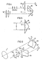
- Figures 1 to 3 show the principle of the invention applied to a telescope
- Figure 4 diagrammatically shows the use of a certain type of optical elements in a telescope
- Figure 5 shows an element included therein
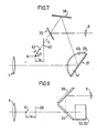
- Figure 6 diagrammatically shows the use of a second type of optical elements and Figure 7 another type of optical elements in connection with the invention
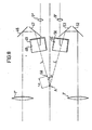
- Figures 8 and 9 diagrammatically show the invention applied to a pair of binoculars
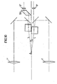
- Figure 10 shows an alternative to the latter
- Figure 11 shows another alternative to the application of the invention in the case of a pair of binoculars.
- the general principle of the present invention is explained in connection with Figures 1, 2 and 3 diagrammatically showing the invention in connection with a telescope.
- the stabilized part consists of the objective lens 1 together with the optical element 2 which may consist of any conceivable combination of lenses, prisms, mirrors and the like, but a requirement is that the element contains at least one reflecting surface. It should be noted that this stabilized part is the most important one for the invention. Its form can be varied in a great many different ways and other optical elements may be added, but this part is found in some form or other in all variants.
- the objective 1 and the optical element 2 are rigidly fixed to each other by an arm or bridging member 3 to which two suitably dimensioned counterweights 4 and 5 may advantageously be fixed.
- a second optical element 6 is, like the ocular 9, rigidly fixed to the casing 7 of the telescope and is accordingly unstabilized.
- Light rays from an observed object first passes the protective plane window 8 and then the objective 1, thereupon passes the elements 2 and 6 and finally the ocular 9.
- the stabilized part is rotatably mounted, substantially without friction, at a pivot point 30 (not shown in Figure 1), the exact position of which will be discussed later. In the case of stabilizing a telescope image, freedom of rotation exists about all axes at right angles to the visual line but not around the latter.
- FIG 4 the essential parts of a telescope are shown, where a threefold reflecting prism 10 is included, shown more in detail in Figure 5.
- This element has the property of reflecting the light non-rotated about the optical axis 11 like a plane mirror but translated the length E, provided that the reflecting planes 12, 13 and 14 are oriented such that each of them contains a line which is parallel to a line in the other planes.
- the U.S. patent No. 3 475 073 is referred to in which other alternative elements with equivalent optical properties are also shown.
- a plane mirror 15 and a roof prism 16 are included which are oriented so that the three reflecting surfaces thereof are at right angles to each other. These surfaces essentially form a cube corner, and henceforth the plane mirror 15 and the roof prims 16 will, accordingly, together be regarded as a cube corner element 17.
- the telescope shown in Figure 4 has exactly the same fundamental construction as the one described in connection with Figures 1 and 2; the threefold reflecting element 10 in Figure 4 thus corresponding to the element 6 in Figure 1, and the cube corner element 17 in Figure 4 corresponding to the element 2 in Figure 1. Consequently, in the case of dimensioning for camera stabilization the pivot point is to be placed where the focus of the objective would have been in the absence of the unstabilized prism 10 at point A.
- the light is reflected six times between objective and ocular. This may seem to be an unnecessary complexity compared, for example, to a porro system where only four reflections occur.
- image stabilization according to this invention, which is described in connection with Figure 6.
- the essential parts of a telescope are shown, containing four mirrors arranged in a well-known way for image reversal.
- the two mirrors 21 and 22 are at right angles to each other and are rigidly connected to the objective 1, said combination being stabilized.
- the mirrors 24 and 25 at right angles to each other are fixed to the casing (not . shown) and are thus unstabilized.
- the stabilized part alone must thus be balanced around an axis and the stabilized part, together with the part of the bearing which is stabilized around only one axis, corresponding to the "middle part" of a cardan ring, must be balanced about the other axis.
- the pivot axis 26, which is parallel to the intersecting line 28 of the unstabilized mirrors, is to be placed so that the axis 26 goes through point B, and the pivot axis 27, which is parallel to the intersecting line 29 of the stabilized mirrors, is to be placed at point C.
- the two pivot axes 26 and 27 are thus to be placed at the distance f Ok from the focus A of the objective 1, where this focus would have been located without the unstabilized mirrors 24 and 25, but on either side of this point.
- the distance between the two pivot axes will here be equal to 2 f ok , which may cause some complication at the balancing. Therefore, it will probably in practice be a good alternative in this case to dimension for camera stabilization and accept the small deterioration which results and which manifests itself such that the image is seen to be stable in relation to the field stop and not in relation to the environment. In practice this is of importance only when the casing makes extremely rapid movements, such as may be the case, for example, when the instrument is fixed to a vibrating support.
- dimensioning for camera stabilization is not suitable, other methods may be used where the disadvantage of separate pivot axes is avoided.
- Dimensioning for telescope stabilization need not be brought about here by moving the pivot point or both pivot axes from the point realizing dimensioning for camera stabilization but, for example, by placing a lens . (or several lenses) such that the requirement that light from an observed object first passes only fully stabilized optics and then passes only unstabilized optics is not satisfied (the flat covering disc in front of the objective is disregarded.
- a negative lens stabilized about one or two axes can be placed so that the light passes this lens before it passes the ocular, or the flat covering disc in front of the objective may be replaced by a positive lens which, if desired, may form part of the objective lens system.
- the pivot point generally cannot be placed exactly on line L.
- Still another method of realizing dimensioning for telescope stabilization in structures where the pivot point is placed for camera stabilization should be mentioned.
- This method is aimed at getting the stabilized part, by servo mechanisms or other means, to move with a certain fraction of the turning movements of the casing in order to modify the degree of stabilization with a certain factor.
- this factor is to be equal to (1 ⁇ 1/F), where F is the magnification of the telescope and where the minus sign applies to instruments in which the image is seen turned upright. If this is the case, then the following relation holds: were a is the angle turned by the casing and (p is the proportional movement of the stabilized part in the same direction.
- the stabilized part consists of the two objectives 1', 1" and the mirrors 46, 47, 52 and 53.
- This unit has a cardan mounting at the pivot point A which is placed for.exact camera stabilization of the two parts of the binoculars; consequently, the focal points of the two objectives, where they would have been without the mirrors 48, 49, 55 and 56, meet at the same point where the pivot point A is situated.
- the optical axes are here wholly in the same plane, the horizontal plane, before reflection occurs in the unstabilized mirrors.
- proportional influencing of the stabilized part may be used with advantage, as this method for natural reasons cannot give rise to possible aberrations or doubling of the images.
- This part consists of an ocular together with corresponding unstabilized pairs of mirrors, and this combination is rotatable around a vertical axis placed for telescope stabilization. If the right ocular 9" is chosen to be adjustable, this ocular and the mirrors 48 and 49 thus have to be rotatable as a unit a small angle around the vertical axis 58 ( Figure 8) which intersects line L and the distance of which to the pivot point A has to be as large as the focal length f Ok of the ocular.
- the two objectives 1' and 1" the mirrors 64, 65, 66 and the pair of roof mirrors 67 are rigidly fixed . to each other and stabilized about the pivot point A which is placed for exact camera stabilization of the two parts of the binoculars.
- the requirement of an equally great rotation in the same direction taking place in both parts of the binoculars is that the angles ⁇ and ⁇ (see the figurer are equal and that an even/uneven number of reflections occur in the unstabilized mirror systems 69 and 70.
- this requirement is here satisfied; the pair of roof mirrors 69 reflects the light two times, the mirror 70 is entirely plane, consequently the light is reflected here only once.
- a variable ocular distance can be realized here as has been described above; which part of the binoculars is chosen for this is here unessential, since the plane mirror 70 and the pair of roof mirrors 69 here give exactly the same result at a rotation about a vertical axis.
- a possible dimensioning for telescope stabilization may suitably be achieved also for this construction by proportional influencing of the stabilized part.
Landscapes
- Physics & Mathematics (AREA)
- General Physics & Mathematics (AREA)
- Optics & Photonics (AREA)
- Telescopes (AREA)
- Adjustment Of Camera Lenses (AREA)
Claims (7)
Applications Claiming Priority (2)
| Application Number | Priority Date | Filing Date | Title |
|---|---|---|---|
| SE8103984A SE426883B (sv) | 1981-06-25 | 1981-06-25 | Bildstabiliserat optiskt instrument |
| SE8103984 | 1981-06-25 |
Publications (2)
| Publication Number | Publication Date |
|---|---|
| EP0082178A1 EP0082178A1 (fr) | 1983-06-29 |
| EP0082178B1 true EP0082178B1 (fr) | 1986-12-17 |
Family
ID=20344145
Family Applications (1)
| Application Number | Title | Priority Date | Filing Date |
|---|---|---|---|
| EP82901993A Expired EP0082178B1 (fr) | 1981-06-25 | 1982-06-18 | Instrument optique a image stabilisee |
Country Status (7)
| Country | Link |
|---|---|
| US (1) | US4542962A (fr) |
| EP (1) | EP0082178B1 (fr) |
| JP (1) | JPS58501147A (fr) |
| AU (1) | AU8585382A (fr) |
| DE (1) | DE3274768D1 (fr) |
| SE (1) | SE426883B (fr) |
| WO (1) | WO1983000067A1 (fr) |
Cited By (1)
| Publication number | Priority date | Publication date | Assignee | Title |
|---|---|---|---|---|
| US9581828B2 (en) | 2012-01-13 | 2017-02-28 | Carl Zeiss Sports Optics Gmbh | Optical system for imaging an object |
Families Citing this family (5)
| Publication number | Priority date | Publication date | Assignee | Title |
|---|---|---|---|---|
| JPH07104543B2 (ja) * | 1988-03-15 | 1995-11-13 | 株式会社ニコン | ケプラー式ファインダー光学系 |
| US5122908A (en) * | 1989-04-21 | 1992-06-16 | Tinsley Laboratories, Inc. | Non-linear controller functions for inertial optical stabilizers |
| US6067194A (en) * | 1997-09-29 | 2000-05-23 | Leica Camera Ag | Image stabilizing instrument |
| US7642741B2 (en) * | 2005-04-27 | 2010-01-05 | Sidman Adam D | Handheld platform stabilization system employing distributed rotation sensors |
| US8179078B2 (en) * | 2005-04-27 | 2012-05-15 | Sidman Adam D | Handheld or vehicle-mounted platform stabilization system |
Citations (2)
| Publication number | Priority date | Publication date | Assignee | Title |
|---|---|---|---|---|
| US3728948A (en) * | 1970-12-28 | 1973-04-24 | Dynasciences Corp | Image motion compensation mechanism |
| US5582190A (en) * | 1994-10-25 | 1996-12-10 | Andrew B. Slavin | Arthroscopic surgical device and method for evaluating and relieving the symptoms of temporomandibular joint disorders |
Family Cites Families (3)
| Publication number | Priority date | Publication date | Assignee | Title |
|---|---|---|---|---|
| US3592180A (en) * | 1969-05-05 | 1971-07-13 | Inst Gas Technology | Gas burner device |
| SU414483A1 (ru) * | 1972-05-11 | 1974-02-05 | , маркшейдерского дела | Нивелир с самоустанавливающейся линиейвизирования |
| JPS4977628A (fr) * | 1972-11-29 | 1974-07-26 |
-
1981
- 1981-06-25 SE SE8103984A patent/SE426883B/sv not_active IP Right Cessation
-
1982
- 1982-06-18 JP JP57502034A patent/JPS58501147A/ja active Granted
- 1982-06-18 EP EP82901993A patent/EP0082178B1/fr not_active Expired
- 1982-06-18 DE DE8282901993T patent/DE3274768D1/de not_active Expired
- 1982-06-18 AU AU85853/82A patent/AU8585382A/en not_active Abandoned
- 1982-06-18 WO PCT/SE1982/000222 patent/WO1983000067A1/fr not_active Ceased
- 1982-06-18 US US06/474,583 patent/US4542962A/en not_active Expired - Lifetime
Patent Citations (2)
| Publication number | Priority date | Publication date | Assignee | Title |
|---|---|---|---|---|
| US3728948A (en) * | 1970-12-28 | 1973-04-24 | Dynasciences Corp | Image motion compensation mechanism |
| US5582190A (en) * | 1994-10-25 | 1996-12-10 | Andrew B. Slavin | Arthroscopic surgical device and method for evaluating and relieving the symptoms of temporomandibular joint disorders |
Cited By (1)
| Publication number | Priority date | Publication date | Assignee | Title |
|---|---|---|---|---|
| US9581828B2 (en) | 2012-01-13 | 2017-02-28 | Carl Zeiss Sports Optics Gmbh | Optical system for imaging an object |
Also Published As
| Publication number | Publication date |
|---|---|
| SE8103984L (sv) | 1982-12-26 |
| US4542962A (en) | 1985-09-24 |
| EP0082178A1 (fr) | 1983-06-29 |
| WO1983000067A1 (fr) | 1983-01-06 |
| AU8585382A (en) | 1983-01-18 |
| DE3274768D1 (en) | 1987-01-29 |
| JPS6261926B2 (fr) | 1987-12-24 |
| SE426883B (sv) | 1983-02-14 |
| JPS58501147A (ja) | 1983-07-14 |
Similar Documents
| Publication | Publication Date | Title |
|---|---|---|
| US4235506A (en) | Image stabilized optical system | |
| US4465346A (en) | Optically stabilized telescope | |
| US4383741A (en) | Binocular night telescope | |
| EP0015061B1 (fr) | Système optique avec stabilisation d'images | |
| US3728948A (en) | Image motion compensation mechanism | |
| US3504957A (en) | Optical stabilized telescope arrangement | |
| US3953106A (en) | Image stabilizing optical system | |
| US3531176A (en) | Multiple telescope stabilizing optical system | |
| EP0082178B1 (fr) | Instrument optique a image stabilisee | |
| US3468595A (en) | Optical stabilization by reflecting means | |
| EP0310514B1 (fr) | Microscope binoculaire | |
| US3797915A (en) | Binocular rangefinder-viewfinder with fresnel optics | |
| US3608995A (en) | Intermediate optical processing stabilizer | |
| US6538812B1 (en) | Telescope and binoculars | |
| US12313857B2 (en) | Optical system for imaging an object, and method for operating the optical system | |
| US3964817A (en) | Optical stabilizer having space referenced motion | |
| US4260218A (en) | Stabilized optical system with off-axis stabilizer | |
| US6362918B1 (en) | Compact keplerian telescope | |
| JP3386813B2 (ja) | コンパクトなケプラー望遠鏡 | |
| US3473861A (en) | Accidental-motion compensation for optical devices | |
| JPH0641208Y2 (ja) | 組合せプリズムおよびこの組合せプリズムを用いた双眼顕微鏡 | |
| US3677618A (en) | Binoculars having stabilizing reflectors | |
| US3460881A (en) | Image stabilizer | |
| US3608997A (en) | Focal plane stabilization system | |
| US3608996A (en) | Optical path detour stabilization system |
Legal Events
| Date | Code | Title | Description |
|---|---|---|---|
| PUAI | Public reference made under article 153(3) epc to a published international application that has entered the european phase |
Free format text: ORIGINAL CODE: 0009012 |
|
| 17P | Request for examination filed |
Effective date: 19830119 |
|
| AK | Designated contracting states |
Designated state(s): DE FR GB |
|
| GRAA | (expected) grant |
Free format text: ORIGINAL CODE: 0009210 |
|
| AK | Designated contracting states |
Kind code of ref document: B1 Designated state(s): DE FR GB |
|
| ET | Fr: translation filed | ||
| REF | Corresponds to: |
Ref document number: 3274768 Country of ref document: DE Date of ref document: 19870129 |
|
| PLBE | No opposition filed within time limit |
Free format text: ORIGINAL CODE: 0009261 |
|
| STAA | Information on the status of an ep patent application or granted ep patent |
Free format text: STATUS: NO OPPOSITION FILED WITHIN TIME LIMIT |
|
| 26N | No opposition filed | ||
| PGFP | Annual fee paid to national office [announced via postgrant information from national office to epo] |
Ref country code: GB Payment date: 19990616 Year of fee payment: 18 |
|
| PGFP | Annual fee paid to national office [announced via postgrant information from national office to epo] |
Ref country code: FR Payment date: 19990617 Year of fee payment: 18 |
|
| PGFP | Annual fee paid to national office [announced via postgrant information from national office to epo] |
Ref country code: DE Payment date: 19990622 Year of fee payment: 18 |
|
| PG25 | Lapsed in a contracting state [announced via postgrant information from national office to epo] |
Ref country code: GB Free format text: LAPSE BECAUSE OF NON-PAYMENT OF DUE FEES Effective date: 20000618 |
|
| GBPC | Gb: european patent ceased through non-payment of renewal fee |
Effective date: 20000618 |
|
| PG25 | Lapsed in a contracting state [announced via postgrant information from national office to epo] |
Ref country code: FR Free format text: LAPSE BECAUSE OF NON-PAYMENT OF DUE FEES Effective date: 20010228 |
|
| REG | Reference to a national code |
Ref country code: FR Ref legal event code: ST |
|
| PG25 | Lapsed in a contracting state [announced via postgrant information from national office to epo] |
Ref country code: DE Free format text: LAPSE BECAUSE OF NON-PAYMENT OF DUE FEES Effective date: 20010403 |