EP0082221B1 - Elektrodenkantenschutz, mit derartigem Elektrodenkantenschutz versehene Elektrode - Google Patents
Elektrodenkantenschutz, mit derartigem Elektrodenkantenschutz versehene Elektrode Download PDFInfo
- Publication number
- EP0082221B1 EP0082221B1 EP81201392A EP81201392A EP0082221B1 EP 0082221 B1 EP0082221 B1 EP 0082221B1 EP 81201392 A EP81201392 A EP 81201392A EP 81201392 A EP81201392 A EP 81201392A EP 0082221 B1 EP0082221 B1 EP 0082221B1
- Authority
- EP
- European Patent Office
- Prior art keywords
- electrode
- edge
- jaws
- inner jaws
- protector
- Prior art date
- Legal status (The legal status is an assumption and is not a legal conclusion. Google has not performed a legal analysis and makes no representation as to the accuracy of the status listed.)
- Expired
Links
- 230000001012 protector Effects 0.000 title claims abstract description 37
- 239000003792 electrolyte Substances 0.000 claims abstract description 9
- 238000009736 wetting Methods 0.000 claims abstract description 4
- 239000011159 matrix material Substances 0.000 claims description 27
- 238000000034 method Methods 0.000 claims description 19
- 239000000463 material Substances 0.000 claims description 11
- 239000002390 adhesive tape Substances 0.000 claims description 6
- 239000000853 adhesive Substances 0.000 claims description 5
- 230000001070 adhesive effect Effects 0.000 claims description 5
- -1 polypropylene Polymers 0.000 claims description 5
- 239000011810 insulating material Substances 0.000 claims description 4
- 229920000728 polyester Polymers 0.000 claims description 4
- 239000004743 Polypropylene Substances 0.000 claims description 3
- 229920001155 polypropylene Polymers 0.000 claims description 3
- 229920001187 thermosetting polymer Polymers 0.000 claims description 3
- 238000013023 gasketing Methods 0.000 claims 1
- 239000012777 electrically insulating material Substances 0.000 abstract description 2
- 239000007858 starting material Substances 0.000 description 8
- RYGMFSIKBFXOCR-UHFFFAOYSA-N Copper Chemical compound [Cu] RYGMFSIKBFXOCR-UHFFFAOYSA-N 0.000 description 5
- RTAQQCXQSZGOHL-UHFFFAOYSA-N Titanium Chemical compound [Ti] RTAQQCXQSZGOHL-UHFFFAOYSA-N 0.000 description 5
- 229910052802 copper Inorganic materials 0.000 description 5
- 239000010949 copper Substances 0.000 description 5
- 239000002659 electrodeposit Substances 0.000 description 5
- 239000010936 titanium Substances 0.000 description 5
- 229910052719 titanium Inorganic materials 0.000 description 5
- 230000015556 catabolic process Effects 0.000 description 4
- 230000000694 effects Effects 0.000 description 4
- 229920001971 elastomer Polymers 0.000 description 4
- 229910052751 metal Inorganic materials 0.000 description 4
- 239000002184 metal Substances 0.000 description 4
- 229920003023 plastic Polymers 0.000 description 4
- 238000004070 electrodeposition Methods 0.000 description 3
- 238000003780 insertion Methods 0.000 description 3
- 230000037431 insertion Effects 0.000 description 3
- 238000004519 manufacturing process Methods 0.000 description 3
- 239000004033 plastic Substances 0.000 description 3
- 238000007670 refining Methods 0.000 description 3
- PXHVJJICTQNCMI-UHFFFAOYSA-N Nickel Chemical compound [Ni] PXHVJJICTQNCMI-UHFFFAOYSA-N 0.000 description 2
- 238000000576 coating method Methods 0.000 description 2
- 239000004020 conductor Substances 0.000 description 2
- 238000010276 construction Methods 0.000 description 2
- 238000005323 electroforming Methods 0.000 description 2
- 238000005363 electrowinning Methods 0.000 description 2
- 238000009413 insulation Methods 0.000 description 2
- 238000002844 melting Methods 0.000 description 2
- 238000001465 metallisation Methods 0.000 description 2
- 150000002739 metals Chemical class 0.000 description 2
- 238000007747 plating Methods 0.000 description 2
- 238000007789 sealing Methods 0.000 description 2
- 229910001220 stainless steel Inorganic materials 0.000 description 2
- 239000010935 stainless steel Substances 0.000 description 2
- 229920000459 Nitrile rubber Polymers 0.000 description 1
- HCHKCACWOHOZIP-UHFFFAOYSA-N Zinc Chemical compound [Zn] HCHKCACWOHOZIP-UHFFFAOYSA-N 0.000 description 1
- 239000007795 chemical reaction product Substances 0.000 description 1
- 229910017052 cobalt Inorganic materials 0.000 description 1
- 239000010941 cobalt Substances 0.000 description 1
- GUTLYIVDDKVIGB-UHFFFAOYSA-N cobalt atom Chemical compound [Co] GUTLYIVDDKVIGB-UHFFFAOYSA-N 0.000 description 1
- 238000000605 extraction Methods 0.000 description 1
- 238000005304 joining Methods 0.000 description 1
- 238000012423 maintenance Methods 0.000 description 1
- 230000008018 melting Effects 0.000 description 1
- 229910052759 nickel Inorganic materials 0.000 description 1
- 150000002825 nitriles Chemical class 0.000 description 1
- 230000000149 penetrating effect Effects 0.000 description 1
- 230000002093 peripheral effect Effects 0.000 description 1
- 229920001084 poly(chloroprene) Polymers 0.000 description 1
- 238000011084 recovery Methods 0.000 description 1
- 238000004064 recycling Methods 0.000 description 1
- 230000008439 repair process Effects 0.000 description 1
- 230000000717 retained effect Effects 0.000 description 1
- ZFXYFBGIUFBOJW-UHFFFAOYSA-N theophylline Chemical compound O=C1N(C)C(=O)N(C)C2=C1NC=N2 ZFXYFBGIUFBOJW-UHFFFAOYSA-N 0.000 description 1
- 239000002699 waste material Substances 0.000 description 1
- 238000004018 waxing Methods 0.000 description 1
- 238000005303 weighing Methods 0.000 description 1
- 229910052725 zinc Inorganic materials 0.000 description 1
- 239000011701 zinc Substances 0.000 description 1
Images
Classifications
-
- C—CHEMISTRY; METALLURGY
- C25—ELECTROLYTIC OR ELECTROPHORETIC PROCESSES; APPARATUS THEREFOR
- C25C—PROCESSES FOR THE ELECTROLYTIC PRODUCTION, RECOVERY OR REFINING OF METALS; APPARATUS THEREFOR
- C25C7/00—Constructional parts, or assemblies thereof, of cells; Servicing or operating of cells
- C25C7/02—Electrodes; Connections thereof
Definitions
- This invention relates to an edge protector for electrodes, e.g. cathode matrix plates as are used in the electrodeposition of metal and, more particularly, in the production of electrodeposits upon, and their subsequent integral detachment from, so-called master-cathodes or matrices in the form of flat plates or sheets, as practised in such processes as electroforming, electrolytic extraction ("electrowinning") and refining of metals.
- edge protector for electrodes e.g. cathode matrix plates as are used in the electrodeposition of metal and, more particularly, in the production of electrodeposits upon, and their subsequent integral detachment from, so-called master-cathodes or matrices in the form of flat plates or sheets, as practised in such processes as electroforming, electrolytic extraction ("electrowinning") and refining of metals.
- starting sheets in electrowinning and electro-refining of such metals as copper, zinc, nickel and cobalt.
- a copper starting sheet serves as the cathode in the production of electrolytic copper, forming the nucleus of the electrodeposited end-product.
- This starting sheet is itself produced by electro- deposition onto a matrix plate from which it is detached; the matrix is then re-used again and again, for as many cycles as possible.
- the matrix is expensive so that it is important to avoid its being damaged during the stripping of the electrodeposited starting sheet. For economic reasons, the stripping process needs to be carried out quickly, so as to speed the recycling of the matrices.
- the process is slowed down, at best, but may result in large numbers of starting sheets being torn or deformed-and, at worst, the valuable matrix may itself be damaged and rendered unserviceable in the stripping process.
- a typical matrix plate may be 3mm (1/8") thick, measuring (in its immersed portion) some 1m x 1m (ca.40"x40") so that each side produces a starting sheet of some l M 2 (ca. 11ft 2 ) in area. It will be seen, therefore, that the stripping process is rendered more difficult when the electrodeposit extends over the vertical edges of the matrix plate, so that a continuous layer surrounds the matrix in the horizontal plane; the bottom edge creates no such problems by itself, if the vertical edges are kept bare, the deposit joining back and front layers across the horizontal bottom edge is simply trimmed off to produce the two separate starting sheets; it is usual practice to provide a 'V'-notched groove along the 3mm wide downward facing base of the matrix plate, and to operate with anodes which are significantly shorter in length than the (matrix) cathodes.
- the electrodeposit reaching the apex of the inverted 'V'-notch is, therefore, extremely thin and readily fractures in a straight line along the apex of the groove when the deposited starting sheets on front and back of the matrix plate are stripped therefrom and folded away from the plate, using the apex-line of the groove as the folding axis. Protection of the grooved base of the matrix plate is required only in special cases (e.g. when there would be adhesion of the deposit within the groove in processes using other than inherently superficially "passive" matrix plates-i.e., other than, e.g. titanium).
- edge protectors have been proposed to prevent metal deposition at the vertical edges of the matrix plate; but none of these devices has remained effective for more than but a relatively few cycles, and partial break-down of such a protector can create additional hazards of damage to electrodeposit and/or matrix during the stripping process. Moreover, waste material from "lace" edges of the deposit requires re-melting which is wasteful of energy and inconvenient. Conventional "stop-off" coatings are porous (especially at the relatively sharp edge of the titanium plate, where such dipped or painted coatings are thinnest), and if thickly applied, their adhesion is inadequate.
- U.S. Patent 3798151 discloses a starter blank for producing a starter sheet for use in an electrolytic metal-refining process having a flexible, resilient, U-shaped frame place upon and around its peripheral edges.
- a wedge is associated with the frame member.
- the wedge is removed from the frame member and the notched portions of the frame member which house the wedge member are squeezed together simulating a lever-and- fulcrumm action. Such action consequently spreads the U-shaped portion of the frame member, hereby facilitating easy insertion of the starter blank within the frame.
- the wedges are subsequently inserted within the notched housing portions, thereby simulating a shrink-fitting operation.
- the bottom portion of the frame is removed, and in lieu thereof, the bottom edge portion of the plate is provided with an inwardly extending V-shaped groove or notch, such configuration aiding the stripping process for the cathode similar to that performed by the removed frame portion relative to the starter blank.
- an edge protector for electrodes comprising first and second elongate elements both elements being of a rigid material which is firstly electrically insulating and secondly is chemically and thermally stable in the intended process environment of the electrode; the first element having a generally 'H'-shaped cross-section so as to define open slots on opposite sides thereof, one slot profiled generally as a circular segment greater than a semi-circle and defined between a pair of outer jaws and the other slot defined between a pair of inner jaws, with an edge of an electrode being insertable into and locatable withing the inner jaws; and the second element being constituted by a member of circular cross-section so dimensioned and shaped for interference snap fitting engagement with the outer jaws, whereby the outer jaws are forced further apart with the result that the outer jaws endeavour to close the inner jaws which are levered towards one another, thereby to exert a uniform pressure upon the edge of the electrode when located within the inner jaws, to form a seal to provent electrolyte from wetting
- the edge protector of the present invention unlike the aforementioned prior art proposals operates without recourse to the "springiness" of its material of construction, nor to the use of adhesives or painted-on layers- other than for the purpose of compensating for surface irregularities as in the manner of a gasket-and its efficiency is unimpaired by the effects of thermal expansion; a number of materials which need not be identical for both elements may be utilised for its construction, and the type selected must, of course, remain unaffected chemically and thermally, by the process environment.
- the principle of operation is simple leverage which not only produces but sustains the necessary forces to maintain efficiency and resistance to dislocation, thus overcoming the shortcomings of existing devices as described in the foregoing. It will be realised that the said "H" configuration is in effect two “levers” (viz., the verticals of the "H”), with the fulcrum-plane represented by the horizontal cross-bar of the "H".
- the two elongate elements of the edge protector may be of substantially equal length as appropriate for the size of the electrode concerned, and made of rigid insulating material, e.g., polypropylene.
- the second element may comprise a multiplicity of elongate pieces, the sum total of their combined lengths being substantially equal to the length of the first element of the edge protector.
- the inner jaws may be so proportioned as to accept the edge of the electrode, inserted therein to a depth of (say) 8-1 Omm, the gap-width being just adequate to accommodate the thickness of the electrode, a so-called friction fit.
- a rubber mallet may be used to force the second element(s) into the outer jaws.
- the second element may be of a material having a greater coefficient of thermal expansion than the material of the first element whereby the leverage action on the inner jaws is enhanced, if as is often the case, the electrode matrix is, in use, employed at elevated temperatures.
- the invention also includes an electrode, of either polarity, e.g., a cathode matrix plate provided with edge protectors as defined above.
- the edge may, with advantage, be gasketed, e.g., by a suitable adhesive tape, such as polyester tape with thermosetting adhesive, applied to the portion of the electrode at and adjacent to the edge which is to be subsequently inserted into the inner jaws.
- a suitable adhesive tape such as polyester tape with thermosetting adhesive
- this edge protector-by itself, or serving as a structural support for attachment of supplementary devices- may be utilised to facilitate precise location of an electrode in the form of a cathode within the cell and/or relative to the anode, both in precision plating processes and for the purpose of preventing accidental short-circuits.
- the edge protector may also be utilised with (insoluble) anode-plates, providing a convenient support for the-attachment of e.g., anode-shields, bipolar or auxiliary electrodes etc.
- the edge protector is equally suitable for attachment to the plate's horizontal bottom edge when this is required.
- the two elongate elements of the edge protector may have such longitudinal dimensions as to protrude beyond the or the immersed length breadth of the electrode to which edge protectors are fitted.
- a piece of compressible and elastic or springy material such as nitrile "rubber” or neoprene ca. 3.5mm thick and some 9mm square may be entrapped within the protruding inner jaws so as to be in close contact with the 3mm (1/8") wide bare or taped bottom edge of the electrode within the inner jaws to prevent metal deposition on that portion (if bare) or to maintain close adhesion thereto of tape, if tape is employed as aforesaid.
- the said protrusions may serve for the additional purposes of locating an electrode plate in a cell and/or maintaining inter electrode distance therein and/or act as structural supports serving the said and/or other purposes, and the said protrusions also protect the bottom edge of the electrode plate when this has to be stood upright on the floor outside the cell during repairs or maintenance to equipment such as conveyors etc.
- the protruding ends of these vertical edge protectors of an electrode plate may also be interconnected by means of a member passing below the horizontal base of the plate.
- the said connecting member may be so designed and constructed as to serve any of the additional purposes as already referred to, and/or to protect the plate's horizontal bottom edge or (merely) its downward-facing base.
- the said member may be attached to the vertical protrusions by means of permanent fixture, or it may be hinged at one end and detachably fastened at the other end, or it may be attached in such a manner as to be readily detachable from the vertical protrusions when required.
- Fixing methods-depending upon the member's shape in profile, etc. include, e.g. mitred joints which may be welded, or gussetted and pinned or bolted, or clamping the ends of the said member within the inner jaws of the protrusions of the vertical edge protectors.
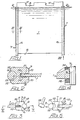
- an electrode (1) in the form of a cathode matrix plate is illustrated immersed in electrolyte the surface of which is indicated at 2, the plate being generally rectangular and provided, at an upper edge 3 above the electrode surface 2 with a plurality of electrical conductors 4 leading to an electrode bar (not shown) of the cell.
- the plate also has a bottom edge 5 illustrated as horizontal and opposed edges 6, which are illustrated as vertical.
- each vertical edge 6 is provided with an edge protector 7 which extends from above the electrolyte surface 2, to below the bottom edge 5.
- each edge protector 7 can be seen to comprise a first elongate element 8 and a second elongate element 9, both of electrically insulating material, e.g., polypropylene.
- the first element 8 is "H"- shaped to provide a pair of inner jaws 10 defining a generally parallel sided slot 11 and a pair of outer jaws 12 defining a generally semi-circular slot 13.
- the edges 6 of the matrix plate are provided with a gasket 14 of polyester tape having a thermosetting adhesive to counter any surface irregularities in the edge 6, the slot 11 being of such a width that the edge 6 and its gasket 14 may be pressed as an interference fit into the slot 11 and be retained there by friction, and this situation has been attained in Figure 5.
- the second element 9 is of circular section and as indicated in Figure 5, is positioned over the slot 13 and tapped into its fully engaged position shown in Figure 2 by a rubber mallet 15 or similar tool.
- the effect of inserting the second element 9 is to force the outer jaws 12 further apart with the result that the inner jaws 10 are levered towards one another thereby exerting greater pressure upon the gasket 14, so that in service, an effective seal is formed by the inner jaws 10, to prevent electrolyte from wetting the edges 6.
- the first element 8 is one piece, the second element can consist of a plurality of individual pieces.
- Figure 4 details the protrusion of an edge protector 7 below the bottom edge 5, the protrusions serving, e.g. as legs and/or for location purposes of the matrix plate within a cell and/orto protect the bottom edge when the matrix plate is stood upright after removal from a cell.
- the protrusions are provided with a piece of nitrile rubber 16 secured between the inner jaws 10, to maintain adhesion of the tape 14 to the base of the matrix plate.
Landscapes
- Chemical & Material Sciences (AREA)
- Engineering & Computer Science (AREA)
- Chemical Kinetics & Catalysis (AREA)
- Electrochemistry (AREA)
- Materials Engineering (AREA)
- Metallurgy (AREA)
- Organic Chemistry (AREA)
- Electrolytic Production Of Metals (AREA)
- Fuses (AREA)
- Push-Button Switches (AREA)
- Connection Of Batteries Or Terminals (AREA)
- Sealing Battery Cases Or Jackets (AREA)
Claims (15)
Priority Applications (3)
| Application Number | Priority Date | Filing Date | Title |
|---|---|---|---|
| AT81201392T ATE18580T1 (de) | 1981-12-23 | 1981-12-23 | Elektrodenkantenschutz, mit derartigem elektrodenkantenschutz versehene elektrode. |
| EP81201392A EP0082221B1 (de) | 1981-12-23 | 1981-12-23 | Elektrodenkantenschutz, mit derartigem Elektrodenkantenschutz versehene Elektrode |
| DE8181201392T DE3174104D1 (en) | 1981-12-23 | 1981-12-23 | Electrode edge protector, electrode provided with such protector |
Applications Claiming Priority (1)
| Application Number | Priority Date | Filing Date | Title |
|---|---|---|---|
| EP81201392A EP0082221B1 (de) | 1981-12-23 | 1981-12-23 | Elektrodenkantenschutz, mit derartigem Elektrodenkantenschutz versehene Elektrode |
Publications (2)
| Publication Number | Publication Date |
|---|---|
| EP0082221A1 EP0082221A1 (de) | 1983-06-29 |
| EP0082221B1 true EP0082221B1 (de) | 1986-03-12 |
Family
ID=8188175
Family Applications (1)
| Application Number | Title | Priority Date | Filing Date |
|---|---|---|---|
| EP81201392A Expired EP0082221B1 (de) | 1981-12-23 | 1981-12-23 | Elektrodenkantenschutz, mit derartigem Elektrodenkantenschutz versehene Elektrode |
Country Status (3)
| Country | Link |
|---|---|
| EP (1) | EP0082221B1 (de) |
| AT (1) | ATE18580T1 (de) |
| DE (1) | DE3174104D1 (de) |
Families Citing this family (4)
| Publication number | Priority date | Publication date | Assignee | Title |
|---|---|---|---|---|
| AT395722B (de) * | 1990-04-23 | 1993-02-25 | Austria Metall | Kathodenbleche aus aluminium fuer die elektrolytische gewinnung von zink |
| DE4325941A1 (de) * | 1993-08-03 | 1995-02-09 | Heraeus Elektrochemie | Verfahren zur Herstellung einer Elektrode sowie Elektrode und deren Verwendung |
| CN106435649B (zh) * | 2016-11-07 | 2018-10-12 | 杨丹虹 | 电解精炼永久阴极板竖边用暗扣式装配并可修复的包边条 |
| SE542768C2 (sv) | 2018-06-29 | 2020-07-07 | Teamx Ab | Anordning vid katodplåt |
Family Cites Families (4)
| Publication number | Priority date | Publication date | Assignee | Title |
|---|---|---|---|---|
| BE746708A (fr) * | 1970-02-27 | 1970-07-31 | Jenatzy Caoutchouc Ind S A | Profile de protection des bords des plaques d'electrolyse, |
| US3830710A (en) * | 1971-01-08 | 1974-08-20 | Int Nickel Co | Masked electrode structure and process for electrolytic deposition of metals |
| JPS514964Y2 (de) * | 1971-10-08 | 1976-02-12 | ||
| US4186074A (en) * | 1979-02-09 | 1980-01-29 | Copper Refineries Pty. Limited | Cathode for use in the electrolytic refining of copper |
-
1981
- 1981-12-23 AT AT81201392T patent/ATE18580T1/de not_active IP Right Cessation
- 1981-12-23 DE DE8181201392T patent/DE3174104D1/de not_active Expired
- 1981-12-23 EP EP81201392A patent/EP0082221B1/de not_active Expired
Also Published As
| Publication number | Publication date |
|---|---|
| ATE18580T1 (de) | 1986-03-15 |
| EP0082221A1 (de) | 1983-06-29 |
| DE3174104D1 (en) | 1986-04-17 |
Similar Documents
| Publication | Publication Date | Title |
|---|---|---|
| US4406769A (en) | Electrode edge protector, electrode provided with such protector and electrodeposits and/or products of electrolysis manufactured by employing such electrodes | |
| CA1082131A (en) | Electrode for the electrolytic deposition of metals | |
| CA1129807A (en) | Organic polymer mandrel for electroforming | |
| AU2007237222B2 (en) | Method for stripping electrodeposited metal sheets and flexing device used therein | |
| US5492609A (en) | Cathode for electrolytic refining of copper | |
| EP0082221B1 (de) | Elektrodenkantenschutz, mit derartigem Elektrodenkantenschutz versehene Elektrode | |
| GB2080829A (en) | Electrode edge protector, | |
| US5919343A (en) | Cathode blank for copper plating | |
| FI79147C (fi) | Katodaggregat foer galvanisk uttfaellning av metaller. | |
| JPS6256590A (ja) | 銅の電解精製用陰極及びその製造方法 | |
| SU1344252A3 (ru) | Катод дл электролитического рафинировани меди | |
| US4357225A (en) | Cathode base plate for electrolytic refining | |
| CN1780939B (zh) | 用于制造阴极板的方法和装置 | |
| US4137130A (en) | Automatic stripping of cathode zinc | |
| EP0873434B1 (de) | Verfahren zur herstellung einer mutterplatte zur elektrolytischen raffination und extraktion und so hergestellte mutterplatte | |
| AU2007203088B2 (en) | An apparatus for stripping electrodeposited metal sheets | |
| KR20010024406A (ko) | 전해정련 또는 전해제련용 전극 및 그 전극의 제조방법 | |
| US3530047A (en) | Stripping of sheet metal electrodeposits from starting sheet blanks | |
| US2536877A (en) | Cathode | |
| KR0171642B1 (ko) | 비철금속 전해전착용 음극 | |
| US4235696A (en) | Mandrel for nickel rounds with a monolithic surface | |
| JPH0515795B2 (de) | ||
| CN1213714A (zh) | 电镀装置 | |
| EP1017883B1 (de) | Verfahren zum halten einer mutterplatte | |
| KR100581466B1 (ko) | 유전재료삽입물을갖는알루미늄음극베이스판 |
Legal Events
| Date | Code | Title | Description |
|---|---|---|---|
| PUAI | Public reference made under article 153(3) epc to a published international application that has entered the european phase |
Free format text: ORIGINAL CODE: 0009012 |
|
| 17P | Request for examination filed |
Effective date: 19821118 |
|
| AK | Designated contracting states |
Designated state(s): AT BE DE SE |
|
| GRAA | (expected) grant |
Free format text: ORIGINAL CODE: 0009210 |
|
| AK | Designated contracting states |
Kind code of ref document: B1 Designated state(s): AT BE DE SE |
|
| REF | Corresponds to: |
Ref document number: 18580 Country of ref document: AT Date of ref document: 19860315 Kind code of ref document: T |
|
| REF | Corresponds to: |
Ref document number: 3174104 Country of ref document: DE Date of ref document: 19860417 |
|
| PLBE | No opposition filed within time limit |
Free format text: ORIGINAL CODE: 0009261 |
|
| STAA | Information on the status of an ep patent application or granted ep patent |
Free format text: STATUS: NO OPPOSITION FILED WITHIN TIME LIMIT |
|
| 26N | No opposition filed | ||
| EAL | Se: european patent in force in sweden |
Ref document number: 81201392.8 |
|
| PGFP | Annual fee paid to national office [announced via postgrant information from national office to epo] |
Ref country code: DE Payment date: 20001129 Year of fee payment: 20 |
|
| PGFP | Annual fee paid to national office [announced via postgrant information from national office to epo] |
Ref country code: SE Payment date: 20001218 Year of fee payment: 20 |
|
| PGFP | Annual fee paid to national office [announced via postgrant information from national office to epo] |
Ref country code: AT Payment date: 20001229 Year of fee payment: 20 |
|
| BE20 | Be: patent expired |
Free format text: 20011223 *BERGER PETER |
|
| PGFP | Annual fee paid to national office [announced via postgrant information from national office to epo] |
Ref country code: BE Payment date: 20010315 Year of fee payment: 20 |
|
| PG25 | Lapsed in a contracting state [announced via postgrant information from national office to epo] |
Ref country code: AT Free format text: LAPSE BECAUSE OF EXPIRATION OF PROTECTION Effective date: 20011223 |
|
| EUG | Se: european patent has lapsed |
Ref document number: 81201392.8 |