EP0082257A2 - Tube de canon muni d'un support pour y fixer des accessoires - Google Patents
Tube de canon muni d'un support pour y fixer des accessoires Download PDFInfo
- Publication number
- EP0082257A2 EP0082257A2 EP82109260A EP82109260A EP0082257A2 EP 0082257 A2 EP0082257 A2 EP 0082257A2 EP 82109260 A EP82109260 A EP 82109260A EP 82109260 A EP82109260 A EP 82109260A EP 0082257 A2 EP0082257 A2 EP 0082257A2
- Authority
- EP
- European Patent Office
- Prior art keywords
- gun barrel
- ring
- barrel
- tube
- screws
- Prior art date
- Legal status (The legal status is an assumption and is not a legal conclusion. Google has not performed a legal analysis and makes no representation as to the accuracy of the status listed.)
- Withdrawn
Links
- 238000010304 firing Methods 0.000 abstract description 3
- 230000003287 optical effect Effects 0.000 abstract description 3
- 230000001133 acceleration Effects 0.000 description 2
- 230000001681 protective effect Effects 0.000 description 2
- 238000005452 bending Methods 0.000 description 1
- 230000005540 biological transmission Effects 0.000 description 1
- 230000005484 gravity Effects 0.000 description 1
- 238000000034 method Methods 0.000 description 1
Images

Classifications
-
- F—MECHANICAL ENGINEERING; LIGHTING; HEATING; WEAPONS; BLASTING
- F41—WEAPONS
- F41G—WEAPON SIGHTS; AIMING
- F41G11/00—Details of sighting or aiming apparatus; Accessories
- F41G11/001—Means for mounting tubular or beam shaped sighting or aiming devices on firearms
Definitions
- the invention relates to a gun barrel with a carrier for attachments to be attached to the gun barrel.
- a weapon barrel is exposed to extreme mechanical and thermal loads.
- pipe widenings, pipe constrictions, longitudinal and transverse vibrations can be observed, which are associated with accelerations that are thousands of times the acceleration due to gravity.
- the invention is based on the object of specifying a weapon barrel with a support for attachments to be attached to the barrel, which enables the attachment to be fastened securely and withstanding all firing loads.
- the carrier 3 consists of a ring 4 encompassing the tube 1 and a base plate 5 connected to it, which lies in a plane running parallel to the longitudinal axis 11 of the tube.
- the ring 4 is slotted on one side, the slot 12 also running parallel to the longitudinal axis 11 of the tube and diametrically opposite the base plate 5.
- the base plate 5 is expediently designed as a cantilever arm projecting beyond the width of the ring 4. In this way, the transmission of pipe vibrations to the additional device 10 can be reduced.
- the ring 4 has an internal thread 2 and can be screwed onto the tube 1 provided with an external thread 13.
- the flanks are preferred for the defined determination of the receiving surfaces in the thread area wise slightly convex.
- the thread base is provided with an undercut and the tips are flattened in the core diameter.
- a locking plate 7 projecting on one side with projections is fastened by means of a fastening screw 8 lying flat on the heads of the tensioning screws 6 in such a way that the projections engage in the tensioning screws 6 designed as hexagon socket screws in order to prevent the tensioning screws from rotating.
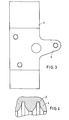
- FIG. 3 shows a top view of the base plate 5 from viewing direction A in FIG. 1.
- the additional device 10 is fastened to this base plate 5 by screws, not shown, and clearance-free fitting pins.
- the contour of the ring 4 of the carrier 3 in connection with its wall thickness and width is selected so that the elongation per unit length of the screws is largely the same, taking into account the materials used.
- the extension lengths of ring 4 and screws 6 are chosen to be as large as possible.
- the weapon barrel with carrier described above enables a reliable attachment of additional devices that withstands all the loads described above.
- the carrier 3 is used in the case of weapon tubes which are provided with a tube protective sleeve 9, at the same time for fastening this tube protective sleeve.
Landscapes
- Engineering & Computer Science (AREA)
- General Engineering & Computer Science (AREA)
- Telescopes (AREA)
- Standing Axle, Rod, Or Tube Structures Coupled By Welding, Adhesion, Or Deposition (AREA)
Applications Claiming Priority (2)
| Application Number | Priority Date | Filing Date | Title |
|---|---|---|---|
| DE19813150123 DE3150123A1 (de) | 1981-12-18 | 1981-12-18 | Waffenrohr mit traeger fuer am waffenrohr zu befestigende zusatzgeraete |
| DE3150123 | 1981-12-18 |
Publications (2)
| Publication Number | Publication Date |
|---|---|
| EP0082257A2 true EP0082257A2 (fr) | 1983-06-29 |
| EP0082257A3 EP0082257A3 (fr) | 1984-05-30 |
Family
ID=6149043
Family Applications (1)
| Application Number | Title | Priority Date | Filing Date |
|---|---|---|---|
| EP82109260A Withdrawn EP0082257A3 (fr) | 1981-12-18 | 1982-10-07 | Tube de canon muni d'un support pour y fixer des accessoires |
Country Status (3)
| Country | Link |
|---|---|
| EP (1) | EP0082257A3 (fr) |
| DE (1) | DE3150123A1 (fr) |
| ES (1) | ES268169Y (fr) |
Cited By (4)
| Publication number | Priority date | Publication date | Assignee | Title |
|---|---|---|---|---|
| DE102005037884B3 (de) * | 2005-08-10 | 2007-01-18 | Heckler & Koch Gmbh | Adapterbauteil |
| WO2004085950A3 (fr) * | 2003-03-27 | 2007-05-03 | Heckler & Koch Gmbh | Adaptateur |
| US8028456B2 (en) | 2006-02-06 | 2011-10-04 | Ashbury International Group, Inc. | Detachable visual augmentation device (VAD) mounting bracket for firearms and optical devices |
| WO2017216069A1 (fr) * | 2016-06-13 | 2017-12-21 | Cmi Defence S.A. | Support d'interface pour un systeme de visée |
Family Cites Families (4)
| Publication number | Priority date | Publication date | Assignee | Title |
|---|---|---|---|---|
| GB108166A (en) * | 1916-05-27 | 1917-07-27 | Charles Oakley Erwood | Improvements in or relating to Gun Sight and Means for Illuminating them. |
| US1428115A (en) * | 1921-04-26 | 1922-09-05 | Perrin Arthur | Sight for firearms |
| FR858032A (fr) * | 1939-03-17 | 1940-11-15 | Silencieux pour armes à feu | |
| US2876545A (en) * | 1957-12-19 | 1959-03-10 | Gabrusti Magur-Lag | Mortar sight |
-
1981
- 1981-12-18 DE DE19813150123 patent/DE3150123A1/de not_active Withdrawn
-
1982
- 1982-10-07 EP EP82109260A patent/EP0082257A3/fr not_active Withdrawn
- 1982-10-26 ES ES1982268169U patent/ES268169Y/es not_active Expired
Cited By (8)
| Publication number | Priority date | Publication date | Assignee | Title |
|---|---|---|---|---|
| WO2004085950A3 (fr) * | 2003-03-27 | 2007-05-03 | Heckler & Koch Gmbh | Adaptateur |
| DE102005037884B3 (de) * | 2005-08-10 | 2007-01-18 | Heckler & Koch Gmbh | Adapterbauteil |
| WO2007017227A1 (fr) | 2005-08-10 | 2007-02-15 | Heckler & Koch Gmbh | Element adaptateur |
| US8028456B2 (en) | 2006-02-06 | 2011-10-04 | Ashbury International Group, Inc. | Detachable visual augmentation device (VAD) mounting bracket for firearms and optical devices |
| WO2017216069A1 (fr) * | 2016-06-13 | 2017-12-21 | Cmi Defence S.A. | Support d'interface pour un systeme de visée |
| BE1025833B1 (fr) * | 2016-06-13 | 2019-10-23 | Cmi Defence Sa | Support d'interface pour un systeme de visée |
| US10928152B2 (en) | 2016-06-13 | 2021-02-23 | Cmi Defence S.A. | Interface support for an aiming system |
| EP3312544A1 (fr) | 2016-10-21 | 2018-04-25 | CMI Defence S.A. | Support d'interface pour un systeme de visée |
Also Published As
| Publication number | Publication date |
|---|---|
| ES268169Y (es) | 1983-11-16 |
| DE3150123A1 (de) | 1983-06-30 |
| ES268169U (es) | 1983-05-01 |
| EP0082257A3 (fr) | 1984-05-30 |
Similar Documents
| Publication | Publication Date | Title |
|---|---|---|
| DE3820471C2 (fr) | ||
| DE3522027A1 (de) | Gewehr mit einer laufhalterung fuer wechsellaeufe | |
| DE102013019165A1 (de) | Zielfernrohrmontage mit einstellbarer Vorneigung | |
| DE3850890T2 (de) | Optisches Halbleitermodul. | |
| US4020577A (en) | Bolt handle adaptor for a bolt action rifle | |
| DE202021000644U1 (de) | Nachtsicht-Vorsatzgerät-Klemmadapter, Nachtsicht-Vorsatzgerät-Klemmadapter-System mit demselben sowie Schusswaffe mit dem Nachtsicht-Vorsatzgerät-Klemmadapter-System | |
| EP0082257A2 (fr) | Tube de canon muni d'un support pour y fixer des accessoires | |
| EP0419916B1 (fr) | Dispositif pour examiner le parallélisme de deux axes | |
| DE7810514U1 (de) | Visierschiene fuer handfeuerwaffen | |
| DE69609038T2 (de) | Befestigungsvorrichtung für ein visierhilfsmittel an einer handfeuerwaffe | |
| WO1999063295A1 (fr) | Arme a feu | |
| DE2759688C2 (de) | Schußwaffe mit verdrehfester Halterung des Laufs | |
| EP0828133A2 (fr) | Bâti à poids léger pour arme à feu | |
| EP0219603B1 (fr) | Dispositif de lancement pour munitions éclairantes | |
| EP0545321B1 (fr) | Niveau à bulle | |
| DE3204152C2 (de) | Vorrichtung zur Befestigung eines Zielfernrohres an einer Schußwaffe | |
| DE19741753C2 (de) | Halterung für Zieleinrichtungen an Kurzwaffen | |
| DE3046639A1 (de) | Einrichtung an einem waffenrohr zur verringerung des abgangsfehlerwinkels | |
| DE19709789C1 (de) | Veränderbare Halterung für Zielgeräte | |
| DE287140C (fr) | ||
| DE3317732A1 (de) | Dreifuss fuer geodaetische instrumente | |
| AT402449B (de) | Verstellbare montagevorrichtung für visiereinrichtungen auf waffen | |
| DE9409365U1 (de) | Laufbefestigung bei Gewehren wobei der Lauf am Schaft befestigt ist | |
| DE3639006C1 (en) | Tube weapon (weapon with a barrel) | |
| EP1524485B1 (fr) | Fusil avec un revetement du canon integré dans la partie anterieure de la crosse |
Legal Events
| Date | Code | Title | Description |
|---|---|---|---|
| PUAI | Public reference made under article 153(3) epc to a published international application that has entered the european phase |
Free format text: ORIGINAL CODE: 0009012 |
|
| AK | Designated contracting states |
Designated state(s): CH DE FR GB IT LI SE |
|
| PUAL | Search report despatched |
Free format text: ORIGINAL CODE: 0009013 |
|
| AK | Designated contracting states |
Designated state(s): CH DE FR GB IT LI SE |
|
| 17P | Request for examination filed |
Effective date: 19840411 |
|
| STAA | Information on the status of an ep patent application or granted ep patent |
Free format text: STATUS: THE APPLICATION IS DEEMED TO BE WITHDRAWN |
|
| 18D | Application deemed to be withdrawn |
Effective date: 19851231 |
|
| RIN1 | Information on inventor provided before grant (corrected) |
Inventor name: JANSSEN, KARL EGON Inventor name: BREUER, HEINZ GUENTER |