EP0082290A2 - Kran mit einer beweglichen Arbeitsplattform - Google Patents
Kran mit einer beweglichen Arbeitsplattform Download PDFInfo
- Publication number
- EP0082290A2 EP0082290A2 EP82110380A EP82110380A EP0082290A2 EP 0082290 A2 EP0082290 A2 EP 0082290A2 EP 82110380 A EP82110380 A EP 82110380A EP 82110380 A EP82110380 A EP 82110380A EP 0082290 A2 EP0082290 A2 EP 0082290A2
- Authority
- EP
- European Patent Office
- Prior art keywords
- support
- work platform
- crane
- console
- post
- Prior art date
- Legal status (The legal status is an assumption and is not a legal conclusion. Google has not performed a legal analysis and makes no representation as to the accuracy of the status listed.)
- Withdrawn
Links
Images





Classifications
-
- E—FIXED CONSTRUCTIONS
- E04—BUILDING
- E04G—SCAFFOLDING; FORMS; SHUTTERING; BUILDING IMPLEMENTS OR AIDS, OR THEIR USE; HANDLING BUILDING MATERIALS ON THE SITE; REPAIRING, BREAKING-UP OR OTHER WORK ON EXISTING BUILDINGS
- E04G1/00—Scaffolds primarily resting on the ground
- E04G1/18—Scaffolds primarily resting on the ground adjustable in height
- E04G1/20—Scaffolds comprising upright members and provision for supporting cross-members or platforms at different positions therealong
-
- B—PERFORMING OPERATIONS; TRANSPORTING
- B66—HOISTING; LIFTING; HAULING
- B66B—ELEVATORS; ESCALATORS OR MOVING WALKWAYS
- B66B9/00—Kinds or types of lifts in, or associated with, buildings or other structures
- B66B9/16—Mobile or transportable lifts specially adapted to be shifted from one part of a building or other structure to another part or to another building or structure
- B66B9/187—Mobile or transportable lifts specially adapted to be shifted from one part of a building or other structure to another part or to another building or structure with a liftway specially adapted for temporary connection to a building or other structure
-
- B—PERFORMING OPERATIONS; TRANSPORTING
- B66—HOISTING; LIFTING; HAULING
- B66C—CRANES; LOAD-ENGAGING ELEMENTS OR DEVICES FOR CRANES, CAPSTANS, WINCHES, OR TACKLES
- B66C23/00—Cranes comprising essentially a beam, boom, or triangular structure acting as a cantilever and mounted for translatory of swinging movements in vertical or horizontal planes or a combination of such movements, e.g. jib-cranes, derricks, tower cranes
- B66C23/18—Cranes comprising essentially a beam, boom, or triangular structure acting as a cantilever and mounted for translatory of swinging movements in vertical or horizontal planes or a combination of such movements, e.g. jib-cranes, derricks, tower cranes specially adapted for use in particular purposes
-
- B—PERFORMING OPERATIONS; TRANSPORTING
- B66—HOISTING; LIFTING; HAULING
- B66F—HOISTING, LIFTING, HAULING OR PUSHING, NOT OTHERWISE PROVIDED FOR, e.g. DEVICES WHICH APPLY A LIFTING OR PUSHING FORCE DIRECTLY TO THE SURFACE OF A LOAD
- B66F11/00—Lifting devices specially adapted for particular uses not otherwise provided for
- B66F11/04—Lifting devices specially adapted for particular uses not otherwise provided for for movable platforms or cabins, e.g. on vehicles, permitting workmen to place themselves in any desired position for carrying out required operations
Definitions
- the invention in question relates to a crane with a movable work platform for consolidated lifting of material, the work platform and workers to a desired height for performing various types of contsruction work on structures higher than 2 meters. Besides that, it serves for taking material in and out of the . structure, as well as for the removal of injured persons from higher structures by way of windows and balconies; it also serves as an auxiliary elevator for lifting and lowering of material.
- Construction work on external surfaces of the structure is performed from pipe scafoolding covered with,boards or from suspended scaffolding.
- the structure must be finished in order for it to be assembled, and suspending scaffolding cannot be assembled on all structures, as it is not suitable for all external operations and the worker does not feel secure enough because of the swaying of the scaffolding, as only a little momentum is needed to separate it from the wall.
- the technical problem lies in how to create a construction which will be, first of all, lightweight, of a reasonably low cost both for private and public sector.
- the construction should easily be transported in a trailer of a passenger car, both in adequate dimensions and in its full weight, should be quickly assembled, should minimally damage the structure (drilling) during its construction; it should also position the work platform on an optimal working height of the worker, use the same mechanism which raises the work platform for loading material on the platform, which would make the machine more effective in performing the work, while on the other hand - cheaper.
- the work platform should be safe for work, should be extendable lengthwise and widened in respect to its optimal width.
- the supporting column should be easily assembled on any type of terrain configuration or hardness, without any special preparation of the terrain.
- the technical problem is solved with a crane with a movable work platform, according to this invention, where the length of the work platform is formed from the elements of the work platform and the above said platform is carried next to the structure along the support posts (which are also formed of its elements of support posts), that being a console which goes under the floor of the work platform, connected to a carriage surrounding the support post.
- the support post is raised by a lifting mechanism by means of a steel cord over an (auxiliary pulley) to a desired height.
- the support post leans on a structure and is fixed to the structure over and under the work platform by means of support posts, while the base on which the support post leans is somewhat bigger than the cross section of the post.
- An auxiliary crane serves for loading material on the work platform. It gets its power from the mechanism which lifts the platform, but with twice the lifting speed than that of lifting the platform.
- the platform could be lifted along one, two or more support posts.
- the crane is produced for various loading capacities. Lifting is performed with electric motors or manually.
- a movable work platform The characteristics of a movable work platform according to this invention, are that construction work may be done on the exterior walls of the structure (as well as on interior walls on structures with high floors), such as: brick-laying, plastering, laying of tiles (marble, insulating, mosaics, etc.), finishing the facade, fixing the facade, carpentry wotk on the exterior, etc.
- the invention can also be used as an auxiliary elevator for taking load in and out. This is made possible because the invention is easily transportable (it can even be transported in a trailer of a passenger car because of its light weight); it can be assembled on any type of ter- ⁇ rain. because the construction of its base permits this.
- a ssemblying is quick because the assembly links are executed in such a way that they are connected with pegs, and these pegs are connected to chains, and, therefore, there is no loss in the search for them.
- the execution of work is enabled by the movable work platform on which there are workers assemblying the elements of the support posts to the desired height.
- the work platform is raised or lowered on the support posts by an electric motor which is controlled by the workers on the platform.
- the crane with the movable work platform assembles on one support post; this is when a shorter work platform is required; the assemblying is then executed on two or more support posts.
- the crane lifts by means of a lifting mechanism, steel cord and a (recessed wheel) along a support post, the work platform, tools, workers and material.
- One characteristic of the work platform is that it can be 50% wider than its optimal width, when the configuration of the wall worked on requires it. This is achieved by supports which are pulled out from the work platform and then boarded.
- movable work platform Another characteristic of the movable work platform is that it can be positioned into the working position, and then, through the use of an auxiliary crane, load material onto the work platform. This is because the speed of the lifting of the work platform is limited by the safety precautions.
- Another characteristic of the invention concerns the choice of the static points of the construction, which tends to lean it towards the wall, and, therefore, makes fallovers minimal. (besides that, the crane has all of the necessary safety precautions).
- the support is attached to the wall with rubber inserts so that, should there be a moment that makes it reflect from the wall, the force embodied in the rubber inserts will oppose it.
- This invention is secured by a protective fence, so that the worker cannot work until the fence is adjusted on the platform. Protection from side swaying is secured by the positioning mechanism.
- Another characteristic of this invention which concerns all of the assembly parts and elements, which can be seen in further descriptions and illsutrations, is that the construction is lighter than the pipe scaffolding several times, and therefore makes the price acceptable for both the private and public sector. (e.g. it is to be foreseen that almost every private house with a ground and first floor will have the need for a one-post crane with a movable work platform for facade repair and for carrying various stuff).
- the final characteristic of the crane with the movable work platform is that it is lighter several times ( as much as 10 times in relation to the pipe scaffolding currently in use) and that to a great extent it will save steel for the country in question, and besides that, there are great savings in first class timber which is used for pipe scaffolding.
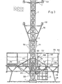
- FIG. 1 designated are subjoints of a two post crane with a movable work platform, which are connected during assemblying on the structure in the following manner: elements of the work platform 04 (the protective fence 05 already assembled) are jointly connected in the upper and lower belts with two pegs 0412, which are secured by safety devices 0414, while the pegs are connected to the chain 0413 in order not to be lost.
- the assemblying of the platform to the desired length is executed next to the wall of the structure on stands 0418, while the carriage console 03 is placed on a specified spot on the platform ("B" darkened triangles), while making sure that the projection of the platform as well as the distance between the posts are not larger than prescribed.
- a support 07 is positioned on the top of the support post in such a way that it is encircled around the support post by means of folding bars 0701 and fastened by peg 0711.
- a support post, assembled in such a way, is straightened from the back side of the platform, but along the vertical axis of the console 03, the sides close left and right 0319, 03191, 0320 and 0325, through joints 0315 which connect the front carriage 0339 and back carriage 0336 by a pin 0337 which is tightened by peg 0311.
- the front carriage is positioned on the supports 0214.
- the support post is placed in the vertical position, and if the work is performed on soft ground, pins 0107 are hammered so that the base would fit into the frame 0103 and the support 0102; on the other hand, if the work is done of hard ground then with the handle 0101 the uniform positioning of the base supports 0110 is achieved whereby the support post is in the -vertical position.
- side support panels (2 pieces) are put on rod 0333 which lies on the connector 0315 and connects the joining rod 0628 to the left and right member 0309, which is welded to the left and right connector 0315.
- the support rod runs through the two members 0309, support pipe 0627 and is tightened by peg 0655, after that the electric control box 12 is assembled, the electric motors connected, and electricity plugged in.
- the recessed wheel 09 is placed on both posts to the level of the supports 07.
- the steel cord 0632 is unwound from the lifting mechanism 06, is placed over the recessed wheel, while the hook 0635 is again tied to the lifting mechanism of the support 0636, while the same is welded to the supporting pipe 0806.
- the wheel 1107 is rolled to the wall so that there is enough clearance between the wall and the wheel carriage 1101, so that the support would not damage the wall during lifting of the platform, while the wheel 1101 compensates for the uneven spots on the wall with the spring 1102.
- the side columns 0501 of the fence are then raised, and on them chains 0509 are tied in three rows, while the column 1501 is then blocked with a peg 0504.
- the electric motor of the lower side 1601 raises the platform to the level which seers to balance the work platform.
- each of the support posts is commanded to jointly rasie the work platform, the workers, the needed tools and a number of supports 07, post elements 02.
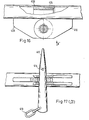
- another support 07 is installed on the support post 02 and secured by two inserts to the structure ( as shown on Figure 15).
- the platform continues to climb further all the way to the level of support 07 which is assembled on the support post 02 on the ground.
- the platform is then positioned on the safety brake 08, so that the worker can from the basket under the work platform, tie the support 07, which hangs on the wall, to the support 02 nLn the already described manner.
- the next step is to remove the upper support 07, assemble the next post element 02, and after two or three extensions of element, tie the support again under the platform and so on to the desired height.
- the work platform 04 is positioned on the safety brake 08 in such a way that the catch 1801 is always in position.
- the catch rests on the bar 0205, then the hook 0635 is released from the support 0636 and the steel cord 0632 is placed over the levelling wheel 1001, and then over the wheel 1006, and so having the load lifted with the same mechanism that raises the platform.
- the load When the load is lifted over the fence 05, with the help of the auxiliary crane 10, the load is positioned to 1002, 1016 and 1010.
- FIG. 3 illustrated is the crane with a movable working platform on a single post support 02.
- the difference in relation to the crane with a double post lies in the fact that only one element of the platform is installed, i.e., the crane with movable platform with a single post is relatively limited by the length of the work platform, and, as the work platform workson a single support post on both sides with projections, then the work platform 04 is positioned by two bars 0415 from the left and right side, tied to the top of the connectors 0315 and the upper rear extended support of the work platform 0402.
- the front end of the console is tied by the members 0344 to the upper front support 0402 to the member 0417.
- Such a stiffly positioned work platform is safe for work on heights.
- the base of 01 encompasses a somewhat larger aerea from the projected cross-section of the support post 02, while it is composed of a steel frame 0103 connected in the center to a support 0102 which is pressed into the soft ground, which secures a horizontal reaction, from the momentum of the support post 02 caused by the maximal load of the work platform 04.
- the support 0102 is hammered into position of the peg 0107.
- the frame When the support 0102 is pressed into position, the frame rests against the ground and receives the. total vertical force transferred from the support post 02.
- the base When working on hard ground, the base is placed on two supports 0110 which are adjusted by a nut 0109, so that both would receive equal vertical and horizontal force.
- the support post 02 serves to carry the maximal load which burdens the carrying console 03 and also serves as the rein to the carriage. It is composed of elements of the support posts.
- the elements of the support posts are composed of welded steel railings which also can be composed of pipe or other profile steel supports. The railing is illustrated on Figures 7, 8 and 9. 1
- the joining of elements of support posts is done in such a way that the first element is welded to the base 04 on points "b", while further connecting is done through the male positioning member 0209 and female positioning member, of which there are three in case of a three sided railing, and four in case of a four sided one.
- the external vertical supports differ in the cross-section, so that the two front supports 0201 near the structure are the same, while the support 0204 which is behind, has a larger cross-section.
- Supports 0201 and 0204 are simultaneously reins for the carriage.
- the front horizontal support - cross-section 0205 serves also for installing the recessed wheel 09 and for the resting of the work platform 04 over the safety brake 08.
- the carriage console serves for 03 carrying the maximal load of the platform 04 and connecting the lifting mechanism 06.
- console 0301 which is made from steel profile supports, most frequently from pipes, with two upper members 0308 joined by a connecting rod 0312, to two mutually tied pipes 0334, which are positioned right and left to the connector 0315, while the two lower members 0307 of the console 0301 are also tied by a connector rod 0312 to the lower part of the left and right connectors 0315.
- Connector rods are tightened by pegs 0311.
- the force in the upper supports of the console 0301 which appears from the load of the work platform 04, is transferred through joint 0323 on sides 0319, 03191, and 0325, symmetrically both from the left and the right side of the support post 02.
- the profiled wheels roll along the rear vertical support 0204 of the support post 02.
- the pressure force in the lower part of the console rail support is transferred on members 0307, then onto the connector rod 0312, and further on to the support of the left and right front carriage 0339 (attached to pipes 0340).
- the pressure force is thus divided into four profiled wheels, two on the left vertical support 0201 and two on the right vertical support 0201.
- the local nebing on the vertical front support 0201 of the post element 02 is lessened twice as much, and a result of that is a smaller cross-section of the support 0201.
- the connectors 0315 On the very top end of the connectors 0315 are nuts which serve for connecting the support 0319 and tension rods 0415 for stiffly positioning the work platform 04. On the very lower end of the connector 0315 there are nuts to which supports and sides 03191, and strong supports 0416 are fastened by bolts.
- Connectors 0315 are joined by a rod 0333 which prevents movement 6f the mechanism around the support rod 0628, while on the other side the rod 0333 facilitates the assemblying of mechanism 06 in such a way that the mechanism 06 is easily positioned for inserting support rods 0628.
- the console 0301 has on the front side at the ends of the upper supports members o344 which are connected to members 0415 from the front part of the work platform 04 on the upper support 0402, i.e. on the side of the object.
- the work platform 04 serves for carrying material, workers who move around on it,and the required tools. It consists of a steel frame which has a triangular cross-section or a trape- zidal as illustrated on Figure 13, depending upon the width of the platform. The frame is so constructively solved that in the so called locations "B" of the darkened aereas, a console 0301 can be inserted.
- Lengthened supports 0402 are placed on the console 0301.
- the element of the work platform 04 is prolonged in length by members, 0406 and.0410 which are connected with pegs. They mutually center themselves with male and female positioning members 0409, 0424.
- the work platform - the tread part 0411 is made from shaped metal which is welded along upper horizontal platform supports. Should the work platform 04 be widened, then the support 0420 is used. This support is carried by members 0421 attached to horizontal transversal support 04011.
- Boards 0422 are placed on the produced supports 0420.
- the support 0420 has on it a member 0423.
- the platform has a stand 0418 on which the work platform 04 is placed while assemblying is being performed.
- the protective fence serves for preventing workers from falling.
- the columns 0501 of the fence connect by way of members to the support 0507 which is welded to the support 04011.
- the whole fence can be disassembled during transport along the work platform 04, and while the work platform 04 is in use, then the fence is raised and secured 0504 on the members 0503.
- the lower part of the protective fence serves to prevent small material and tools from falling out.
- the chains on one end end with a hook 0517 so that they can be easily removed to permit passing.
- the fences join by connectors.
- the lifting mechanism 06 serves for raising and lowering the console and carriage 03 with the work platform maximally loaded.
- the mechanism cosists of an electric motor 06-01 connected to a transmission housing 0605 in which there is a transmission 0604 with a connector bearing, with one part in the electric motor and one part on two inverse radio-axial bearings 0608, while on the upper part of the transmission there is a brake 0614 which brakes in all positions except when the running of the motor is in the direction of lifting the platform.
- the transmission housing 0605 is connected with sheet metal with the possibility of adjusting the clearance on the transmission wheel by way of supporters which absorb transversal and longitudinal forces for the left and side sheet metal 0624.
- the left and right sheet metal 0624 is carried by the transmission wheel 0606 which is connected to a drum 0647.
- The" drum 0647 ties to itself the steel cord 0632, and both entwine with two harnesses 0654 and harness 0627.
- the connecting of the lifting mechanism 06 to the carriage console 03 is done in such way that the notches of the sheet metal 0624 are placed on the rod 0333, then the support rod 0628 is pulled through the member 0309 and the support pipes 0627.
- the support rod is tightened by a peg 0636, while the hook 0635 is placed over the recessed wheel 09 and tied to the support 0636.
- the wall support 07 serves for supporting.the support post 02 on the wall. It accepts horizontal and side forces from the harness which produces maximal load of the platform 04. The reason wha the support is wider on the ends 0723 is that it prevents the side forces which could result in the falling of the crane.
- the support consists of a steel frame 0716, joint rods 0723 which can be lengthened or shortened depending on the required workand the wall configuration.
- the support rests on the screw 0712, and it on the member 0719, and together they form a joint which makes possible that the support 07 can be lowered to hang down the wall, which would enable the platform 04 to pass by the support, so that it would again be able to attach to the support post 02, although under the work platform 04.
- the member 0719 is welded to the plate with rubber thereon 0717 which has rubber 0720 stuck on it to create friction, and not damage the wall.
- the plate with rubber thereon 0717 has a holw through which another hole is made for positioning the rubber insert with the screw 0721, reinforced rubber pipes 0722, foundation 0711, and butterfly screws (0710).
- the safety brake 08 serves in cases of breaking of the steel cord 0632 or if the brake 0614 fails. It "grabs" the bar 0205 of the support post 02. It also serves for adjusting work platforms 04 into the working position when the steel cord 063 2 is used for lifting loads by way of the auxiliary crane 10.
- the safety brake consists of a pipe support 0806 which goes over the supported pipe 0627. Two supports are welded on the support 0806, while a handle 1801 is welded on the two supports.
- the handle is always directed downwards by the spring 0808 and the member 0805, during movement of the work platform, if the worker does not do anything to overcome the spring.
- the catch will then linger on the bar 0205 of the support post 02.
- the recessed wheel 09 serves for raising the carriage console 03 along with the work platform 04 and the lifting mechanism 06, as well as for lifting of load through the help of the auxiliary crane 10.
- the recessed wheel 09 consists of the wheel 0902 which turns on the wheel support 0911, while the support 0911 is welded to the support pipe 1910 which is shortened in length so that it would not fall off the rod 0205 of the support post 02, on which it leans anyway.
- the member is placed under the rods of horizontal supports 0206 of the support post 02.
- the recessed wheel When the recessed wheel is used for lifting the carriage console 03 and the . work platform,. then the recessed wheel functions as an auxiliary wheel because the steel rope is tied by both ends to the lifting mechanism, while, when it lifts load by way of the auxiliary crane 10, then it functions as a stationary wheel and then it raises loads at double the speed.
- the auxiliary crane 10 serves for lifting and placing load onto the working platform 04. It consists of two pegs 1017 which attach themselves to the support posts 02 on the level of the recessed wheel.
- the steel cord is placed over the levelling wheel grooves 1001, then over the wheel 1006.
- the rotating console 1010 turns on the handles 1002, 1016.
- the vertical support 1009 is tightly connected to the handles 1002 and 1016, as well as to the pegs 1017, so that only the console rotates while everything else remains stationary.
- the positioning mechanism on the work platform 11 serves for preventing swaying of the work platform, and in some cases takes the place of supports. It consists of a support 1101 which carries the wheel 1107 on the spring 1102 and two side supports 1103.
- the support 1101 connects to the tread 0411 through the support 1110 and fixes the distance with butterfly screws 1104. If an elastic connection is desired, this is when the - platform is moving, then the wheel is positioned to the wall and travels against the wall, with the springs 1102 compensating for uneven parts.
- the support When a stiffer connection is desired, the support is pushed to touch the wall, then fixed in position by butterfly screws. This is when the elements are extended making the connection less flexible.
- Electric control box 12 is used for control of electric motors, " up”, “down” and “stop”, for each motor separately and all tog e ther, and is further furnished with end switchers for up and down movement.
- Basket 13 is used for fixation and defixation of wall support 07 below the platform 04, and is occupied by a worker.
- the basket is comprised of a steel frame and is connected by means of bolts to members 0417.
Landscapes
- Engineering & Computer Science (AREA)
- Structural Engineering (AREA)
- Mechanical Engineering (AREA)
- Civil Engineering (AREA)
- Architecture (AREA)
- Life Sciences & Earth Sciences (AREA)
- Geology (AREA)
- Transportation (AREA)
- Automation & Control Theory (AREA)
- Jib Cranes (AREA)
Applications Claiming Priority (2)
| Application Number | Priority Date | Filing Date | Title |
|---|---|---|---|
| YU266581A YU266581A (en) | 1981-11-11 | 1981-11-11 | Crane with a movable working platform |
| YU2665/81 | 1981-11-11 |
Publications (2)
| Publication Number | Publication Date |
|---|---|
| EP0082290A2 true EP0082290A2 (de) | 1983-06-29 |
| EP0082290A3 EP0082290A3 (de) | 1984-12-19 |
Family
ID=25558507
Family Applications (1)
| Application Number | Title | Priority Date | Filing Date |
|---|---|---|---|
| EP82110380A Withdrawn EP0082290A3 (de) | 1981-11-11 | 1982-11-10 | Kran mit einer beweglichen Arbeitsplattform |
Country Status (2)
| Country | Link |
|---|---|
| EP (1) | EP0082290A3 (de) |
| YU (1) | YU266581A (de) |
Cited By (16)
| Publication number | Priority date | Publication date | Assignee | Title |
|---|---|---|---|---|
| FR2624173A1 (fr) * | 1987-12-07 | 1989-06-09 | Cavalieri Michel | Echafaudage grimpant a plate-forme constituant un tout unitaire |
| WO1994005588A1 (de) * | 1992-09-02 | 1994-03-17 | Franz Krempelmeier | Hebebühne |
| DE9412626U1 (de) * | 1994-08-04 | 1994-10-06 | Bilfinger + Berger Bauaktiengesellschaft, 68165 Mannheim | Vorrichtung zur Montage und Demontage von Turmdrehkränen |
| GB2387833A (en) * | 2002-04-15 | 2003-10-29 | E M & I | A mobile access system and method of access thereof |
| JP2009544550A (ja) * | 2006-07-24 | 2009-12-17 | オーチス エレベータ カンパニー | エレベータ |
| CN102765682A (zh) * | 2012-07-30 | 2012-11-07 | 无锡华科机械设备有限公司 | 吊篮安装架 |
| CN107060308A (zh) * | 2017-03-17 | 2017-08-18 | 南通理工学院 | 一种窗外作业台架 |
| CN111021808A (zh) * | 2019-12-09 | 2020-04-17 | 大唐东营发电有限公司 | 一种火力发电厂用的电能输送安装桩 |
| CN111533002A (zh) * | 2020-06-04 | 2020-08-14 | 江苏庞源机械工程有限公司 | 一种用于塔式起重机附着点墙体开裂加固连接件 |
| CN113213315A (zh) * | 2021-06-17 | 2021-08-06 | 江苏阿尔法电梯制造有限公司 | 一种建筑隔墙板用转运方法 |
| CN113979328A (zh) * | 2021-11-22 | 2022-01-28 | 中国二十冶集团有限公司 | 一种配电装置吊装设备、配电装置安装系统及安装方法 |
| CN114105001A (zh) * | 2021-11-16 | 2022-03-01 | 中建三局集团有限公司 | 装配式塔机塔身悬挑平台及其安装方法 |
| CN114232973A (zh) * | 2022-01-26 | 2022-03-25 | 遂昌县匠锐机械设计有限公司 | 一种钢结构工程施工用高空作业平台 |
| CN114482512A (zh) * | 2022-02-28 | 2022-05-13 | 广东电网有限责任公司广州供电局 | 一种换流阀侧面组件安装及检修用吊篮和作业方法 |
| CN116838066A (zh) * | 2023-06-16 | 2023-10-03 | 郑州一建集团有限公司 | 一种用于砌墙粉刷的移动升降平台 |
| CN117400208A (zh) * | 2023-10-20 | 2024-01-16 | 中建三局第二建设工程有限责任公司 | 一种用于塔吊片式标准节的安装支架 |
Family Cites Families (4)
| Publication number | Priority date | Publication date | Assignee | Title |
|---|---|---|---|---|
| US3244258A (en) * | 1963-09-11 | 1966-04-05 | Charles G Neidert | Hoisting equipment |
| US3291257A (en) * | 1965-05-19 | 1966-12-13 | Forest M Ellis | Climber-type scaffold |
| US3323616A (en) * | 1965-10-22 | 1967-06-06 | Frank S Best | Mason's scaffold |
| FR2482995A3 (fr) * | 1980-05-22 | 1981-11-27 | Piat Impalcature Automatiche S | Echafaudage decomposable pour supporter des ponts et des plate-formes mobiles |
-
1981
- 1981-11-11 YU YU266581A patent/YU266581A/xx unknown
-
1982
- 1982-11-10 EP EP82110380A patent/EP0082290A3/de not_active Withdrawn
Cited By (23)
| Publication number | Priority date | Publication date | Assignee | Title |
|---|---|---|---|---|
| FR2624173A1 (fr) * | 1987-12-07 | 1989-06-09 | Cavalieri Michel | Echafaudage grimpant a plate-forme constituant un tout unitaire |
| WO1994005588A1 (de) * | 1992-09-02 | 1994-03-17 | Franz Krempelmeier | Hebebühne |
| DE9412626U1 (de) * | 1994-08-04 | 1994-10-06 | Bilfinger + Berger Bauaktiengesellschaft, 68165 Mannheim | Vorrichtung zur Montage und Demontage von Turmdrehkränen |
| GB2387833A (en) * | 2002-04-15 | 2003-10-29 | E M & I | A mobile access system and method of access thereof |
| GB2387833B (en) * | 2002-04-15 | 2005-04-13 | E M & I | A mobile access system and method |
| JP2009544550A (ja) * | 2006-07-24 | 2009-12-17 | オーチス エレベータ カンパニー | エレベータ |
| US20100018811A1 (en) * | 2006-07-24 | 2010-01-28 | Davide Vaudo | Elevators |
| CN102765682A (zh) * | 2012-07-30 | 2012-11-07 | 无锡华科机械设备有限公司 | 吊篮安装架 |
| CN102765682B (zh) * | 2012-07-30 | 2014-09-03 | 无锡华科机械设备有限公司 | 吊篮安装架 |
| CN107060308B (zh) * | 2017-03-17 | 2022-11-04 | 南通理工学院 | 一种窗外作业台架 |
| CN107060308A (zh) * | 2017-03-17 | 2017-08-18 | 南通理工学院 | 一种窗外作业台架 |
| CN111021808A (zh) * | 2019-12-09 | 2020-04-17 | 大唐东营发电有限公司 | 一种火力发电厂用的电能输送安装桩 |
| CN111021808B (zh) * | 2019-12-09 | 2021-05-11 | 大唐东营发电有限公司 | 一种火力发电厂用的电能输送安装桩 |
| CN111533002A (zh) * | 2020-06-04 | 2020-08-14 | 江苏庞源机械工程有限公司 | 一种用于塔式起重机附着点墙体开裂加固连接件 |
| CN113213315A (zh) * | 2021-06-17 | 2021-08-06 | 江苏阿尔法电梯制造有限公司 | 一种建筑隔墙板用转运方法 |
| CN113213315B (zh) * | 2021-06-17 | 2024-04-26 | 江苏阿尔法电梯制造有限公司 | 一种建筑隔墙板用转运方法 |
| CN114105001A (zh) * | 2021-11-16 | 2022-03-01 | 中建三局集团有限公司 | 装配式塔机塔身悬挑平台及其安装方法 |
| CN114105001B (zh) * | 2021-11-16 | 2023-07-18 | 中建三局集团有限公司 | 装配式塔机塔身悬挑平台及其安装方法 |
| CN113979328A (zh) * | 2021-11-22 | 2022-01-28 | 中国二十冶集团有限公司 | 一种配电装置吊装设备、配电装置安装系统及安装方法 |
| CN114232973A (zh) * | 2022-01-26 | 2022-03-25 | 遂昌县匠锐机械设计有限公司 | 一种钢结构工程施工用高空作业平台 |
| CN114482512A (zh) * | 2022-02-28 | 2022-05-13 | 广东电网有限责任公司广州供电局 | 一种换流阀侧面组件安装及检修用吊篮和作业方法 |
| CN116838066A (zh) * | 2023-06-16 | 2023-10-03 | 郑州一建集团有限公司 | 一种用于砌墙粉刷的移动升降平台 |
| CN117400208A (zh) * | 2023-10-20 | 2024-01-16 | 中建三局第二建设工程有限责任公司 | 一种用于塔吊片式标准节的安装支架 |
Also Published As
| Publication number | Publication date |
|---|---|
| EP0082290A3 (de) | 1984-12-19 |
| YU266581A (en) | 1984-02-29 |
Similar Documents
| Publication | Publication Date | Title |
|---|---|---|
| US4828073A (en) | Mobile suspended scaffold | |
| CN112761348A (zh) | 一种无配重式吊篮悬吊系统及安装方法 | |
| WO2006075192A1 (en) | Apparatus for use in the construction of buildings | |
| CA1311784C (en) | Apparatus for affixing a scaffolding member to a structure | |
| US4382488A (en) | Pump jack poles | |
| CN118855211B (zh) | 一种吊篮安装方法 | |
| CN110805289A (zh) | 插接式卸料平台及施工方法 | |
| CN215907365U (zh) | 一种高空连廊结构底部施工辅助操作平台 | |
| JPS6160947B2 (de) | ||
| KR20250111746A (ko) | 모노레일 시스템 및 관련 비계 구조물, 시스템 및 사용 방법 | |
| CN219260998U (zh) | 一种锚索张拉器 | |
| CN117163118A (zh) | 一种利用专用运输小车安装盘柜的施工方法 | |
| CN215405586U (zh) | 一体式电动爬升悬吊平台机械装置 | |
| CN212388956U (zh) | 建筑物倾斜结构柱施工用悬吊作业平台 | |
| IE900151A1 (en) | A Construction of Ladder | |
| CN108868136A (zh) | 卸料平台的加固装置 | |
| CN2237084Y (zh) | 插销式升降脚手架 | |
| JP3315312B2 (ja) | 工事用エレベータの鉄塔組立・解体装置 | |
| EP1801318A1 (de) | Fahrzeug zum Transport von Werkstoffen an Gebaeudeaussenseiten | |
| PL110399B1 (en) | Collapsible scaffolding | |
| KR102580297B1 (ko) | 작업자의 탑승이 가능하고 교축방향의 주행이 가능한교량 시공작업용 주행 대차 | |
| JP7747154B1 (ja) | 高所作業台 | |
| JP7112146B1 (ja) | 移動連結吊り足場及びその使用方法 | |
| JPH0328066Y2 (de) | ||
| CN222478204U (zh) | 一种多高层钢结构的型钢梁的辅助装配装置 |
Legal Events
| Date | Code | Title | Description |
|---|---|---|---|
| PUAI | Public reference made under article 153(3) epc to a published international application that has entered the european phase |
Free format text: ORIGINAL CODE: 0009012 |
|
| AK | Designated contracting states |
Designated state(s): CH DE FR LI |
|
| RBV | Designated contracting states (corrected) |
Designated state(s): CH DE FR LI |
|
| PUAL | Search report despatched |
Free format text: ORIGINAL CODE: 0009013 |
|
| AK | Designated contracting states |
Designated state(s): CH DE FR LI |
|
| 17P | Request for examination filed |
Effective date: 19850613 |
|
| 17Q | First examination report despatched |
Effective date: 19860310 |
|
| STAA | Information on the status of an ep patent application or granted ep patent |
Free format text: STATUS: THE APPLICATION IS DEEMED TO BE WITHDRAWN |
|
| 18D | Application deemed to be withdrawn |
Effective date: 19860603 |