EP0082360A1 - Kühlvorrichtung für elektrischen Transformator - Google Patents
Kühlvorrichtung für elektrischen Transformator Download PDFInfo
- Publication number
- EP0082360A1 EP0082360A1 EP19820111078 EP82111078A EP0082360A1 EP 0082360 A1 EP0082360 A1 EP 0082360A1 EP 19820111078 EP19820111078 EP 19820111078 EP 82111078 A EP82111078 A EP 82111078A EP 0082360 A1 EP0082360 A1 EP 0082360A1
- Authority
- EP
- European Patent Office
- Prior art keywords
- cooling
- air
- cooling device
- cooling means
- tubing
- Prior art date
- Legal status (The legal status is an assumption and is not a legal conclusion. Google has not performed a legal analysis and makes no representation as to the accuracy of the status listed.)
- Withdrawn
Links
Images


Classifications
-
- H—ELECTRICITY
- H01—ELECTRIC ELEMENTS
- H01F—MAGNETS; INDUCTANCES; TRANSFORMERS; SELECTION OF MATERIALS FOR THEIR MAGNETIC PROPERTIES
- H01F27/00—Details of transformers or inductances, in general
- H01F27/08—Cooling; Ventilating
- H01F27/20—Cooling by special gases or non-ambient air
-
- H—ELECTRICITY
- H01—ELECTRIC ELEMENTS
- H01F—MAGNETS; INDUCTANCES; TRANSFORMERS; SELECTION OF MATERIALS FOR THEIR MAGNETIC PROPERTIES
- H01F27/00—Details of transformers or inductances, in general
- H01F27/08—Cooling; Ventilating
- H01F27/10—Liquid cooling
- H01F27/12—Oil cooling
Definitions
- This invention relates to a cooling device for an electric transformer, and, more particularly, it is concerned with a cooling device for an electric transformer which performs cooling of such transformer by natural convection of air.
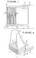
- this type of the cooling device for the electric transformer is so constructed, as shown in Figure 1, that both ends of each of a multitude of cooling tubes 1, 1, ... juxtaposed in parallel at predetermined space intervals among them are connected with two tubes 2, 2 disposed in the direction perpendicular to these cooling tubes, one end of these tubes 2, 2 being closed and the other end thereof being connected with the main body 3 of the transformer.
- a forced circulation device 4 for a cooling medium is further connected to the base part of one of the tubes 2, 2 to cause the cooling medium to flow through the tubes as shown by arrow marks in solid line, while air flows in natural convection outside the cooling tubes 1, 1 bib in the direction of arrow marks in dotted line.
- the cooling device of the above-described construction since the heat transfer rate between air and the cooling tubes 1, 1, Vietnamese is very small in comparison with the heat transfer rate between the cooling medium and the cooling tubes, the dimension of the cooling device is governed by a heat transfer area for obtaining a required quantity of heat passage between air and the cooling tubes 1, 1, ; Accordingly, in the above-described conventional construction of the cooling device, a broader heat transfer area had to be secured for passage of heat between air and the cooling tubes.
- the height of the cooling tube is increased to secure the required heat transfer area
- acquisition of the required heat transfer area has been done mainly by increasing the number of cooling tubes with the consequent problem of a larger installation area having been required.
- the present invention taking note of the above-described points of problem in the conventional cooling device, has been made with a view to improving such disadvantage inherent in the known device.
- a cooling device for an electric transformer which comprises: a) a cooling means disposed in the horizontal direction and through which cooling medium passes ; b) first and second headers provided at an inlet side and an outlet side of said cooling means; c) first tubing to lead the cooling medium which has cooled the transformer to said first header ; d) second tubing to lead the cooling medium in said cooling means into said transformer through said second header; and e) a duct to lead air to the upper part of said cooling means after completion of the heat-exchange between said cooling medium in said cooling means and air.
- Figure 2 is a plan view illustrating one embodiment of the cooling device according to the present invention
- Figure 3 shows a front view of the same
- Figure 4 shows a perspective view of the cooling device of Figure 2 as viewed along a line A-A' in Figure 2.
- reference numeral 1, 1, ?? designates cooling tubes, in the interior of which an insulated gas as a cooling medium flows, while air flows between adjacent tubes in the natural convection. Both ends of these cooling tubes 1, 1, .... are connected with headers 5, 5 for coupling the gas pipes 2, 2.
- a frusto-conical gas discharging duct 7 having an opening 6 at its top end
- legs 8, 8 which support the entire cooling device at a position floated from the floor surface so that air may flow thereinto from the bottom part thereof as shown by arrow marks in dotted lines, climb up inside the air discharging duct 7, and be discharged from the top end of the opening 6.
- a reference numeral 3 designates a main body of the electric transformer, and 4 refers to a forced circulation device.
- Figure 5 shows the cooling device not equipped with the gas discharging duct 7 and a passage route of air in its natural convection
- Figure 6 shows a temperature distribution of air in correspondence to height of the cooling device shown in Figure 5, the temperature changing in the direction of an arrow mark.
- a portion a in Figure 6 indicates that air climbs up through the space gap between adjacent cooling tubes 1, 1, Vietnamese and its temperature changes from ⁇ 1 to ⁇ 2 .
- Portions b and c in the same drawing indicate a route, through which the heated air is diffused from the opening portion, cooled again to the temperature O 1 , and reaches an inlet at the lower part of the cooling device.
- a pressure to cause the air to flow into the space gap between the adjacent cooling tubes at the inlet part for the air at the lower part of the cooling device is developed by a difference in the density of air between the upper exit part of the device and the lower inlet part thereof, and is represented by the following equation.
- H R represents a height of the cooling tube 1 as shown in Figure 5.
- Figure 7 illustrates the cooling device provided with the gas discharging duct 7, and a passage route for air in its natural convection.
- Figure 8 shows a temperature distribution of air in correspondence to the height of the cooling device shown in Figure 7.
- a portion a indicates that the air rises through the space gap between the adjacent cooling tubes 1, 1, ...., and the temperature changes from ⁇ 1 to ⁇ 2 .
- a portion d indicates that the air at the temperature On rises upwards in the gas discharging duct 7.
- the portions b and c illustrate the passage route, through which heated air is diffused from the opening portion 6 and cooled again to the temperature ⁇ 1 to reach the inlet port at the lower part of the cooling device.
- a pressure to cause the air to flow into the inlet port at the lower part of the device is developed by a difference in the density of air between the upper part of the gas discharging duct 7 and the lower inlet part of the cooling device, and is represented by the following equation.
- H T represents a height of the gas discharging duct 7 as shown in Figure 7.
- the other symbols are the same as in the equation (1).
- the present invention is able to improve the heat transfer rate between air and the cooling tubes by the provision of the gas discharging duct at the air exit port atop the arrangement of the cooling tubes, so that the area for installation of the cooling device can be effectively decreased for the improved heat transfer rate.
Landscapes
- Engineering & Computer Science (AREA)
- Power Engineering (AREA)
- Transformer Cooling (AREA)
Applications Claiming Priority (2)
| Application Number | Priority Date | Filing Date | Title |
|---|---|---|---|
| JP199665/81 | 1981-12-09 | ||
| JP19966581A JPS58100408A (ja) | 1981-12-09 | 1981-12-09 | 変圧器の冷却装置 |
Publications (1)
| Publication Number | Publication Date |
|---|---|
| EP0082360A1 true EP0082360A1 (de) | 1983-06-29 |
Family
ID=16411586
Family Applications (1)
| Application Number | Title | Priority Date | Filing Date |
|---|---|---|---|
| EP19820111078 Withdrawn EP0082360A1 (de) | 1981-12-09 | 1982-12-01 | Kühlvorrichtung für elektrischen Transformator |
Country Status (2)
| Country | Link |
|---|---|
| EP (1) | EP0082360A1 (de) |
| JP (1) | JPS58100408A (de) |
Cited By (3)
| Publication number | Priority date | Publication date | Assignee | Title |
|---|---|---|---|---|
| EP0500390A1 (de) * | 1991-02-22 | 1992-08-26 | Kabushiki Kaisha Toshiba | Gasisoliertes, elektrisches Gerät |
| EP0551554A1 (de) * | 1992-01-17 | 1993-07-21 | Mitsubishi Denki Kabushiki Kaisha | Kühleinrichtung für den Bordtransformator einer elektrischen Lokomotive |
| CN112614655A (zh) * | 2020-12-03 | 2021-04-06 | 安徽晶飞科技有限公司 | 一种变压器用降温装置及其工作方法 |
Citations (5)
| Publication number | Priority date | Publication date | Assignee | Title |
|---|---|---|---|---|
| AT101584B (de) * | 1924-10-13 | 1925-11-10 | Nordon Freres Fa | Umlaufkühlvorrichtung für elekrische Maschinen, insbesondere für Behälter von Öltransformatoren. |
| US1711364A (en) * | 1925-09-22 | 1929-04-30 | Roothaan Jan | Oil-cooled transformer |
| CH150095A (de) * | 1929-09-25 | 1931-10-15 | Siemens Ag | Luftgekühlter Fahrzeugtransformator. |
| GB391556A (en) * | 1932-01-27 | 1933-05-04 | Serck Radiators Ltd | Improvements in tubular apparatus for exchanging heat between fluids, applicable to electrical transformer tanks |
| CH607261A5 (de) * | 1975-05-12 | 1978-11-30 | Gec South Africa Pty |
-
1981
- 1981-12-09 JP JP19966581A patent/JPS58100408A/ja active Pending
-
1982
- 1982-12-01 EP EP19820111078 patent/EP0082360A1/de not_active Withdrawn
Patent Citations (5)
| Publication number | Priority date | Publication date | Assignee | Title |
|---|---|---|---|---|
| AT101584B (de) * | 1924-10-13 | 1925-11-10 | Nordon Freres Fa | Umlaufkühlvorrichtung für elekrische Maschinen, insbesondere für Behälter von Öltransformatoren. |
| US1711364A (en) * | 1925-09-22 | 1929-04-30 | Roothaan Jan | Oil-cooled transformer |
| CH150095A (de) * | 1929-09-25 | 1931-10-15 | Siemens Ag | Luftgekühlter Fahrzeugtransformator. |
| GB391556A (en) * | 1932-01-27 | 1933-05-04 | Serck Radiators Ltd | Improvements in tubular apparatus for exchanging heat between fluids, applicable to electrical transformer tanks |
| CH607261A5 (de) * | 1975-05-12 | 1978-11-30 | Gec South Africa Pty |
Cited By (4)
| Publication number | Priority date | Publication date | Assignee | Title |
|---|---|---|---|---|
| EP0500390A1 (de) * | 1991-02-22 | 1992-08-26 | Kabushiki Kaisha Toshiba | Gasisoliertes, elektrisches Gerät |
| US5252778A (en) * | 1991-02-22 | 1993-10-12 | Kabushiki Kaisha Toshiba | Gas-insulated electric apparatus |
| EP0551554A1 (de) * | 1992-01-17 | 1993-07-21 | Mitsubishi Denki Kabushiki Kaisha | Kühleinrichtung für den Bordtransformator einer elektrischen Lokomotive |
| CN112614655A (zh) * | 2020-12-03 | 2021-04-06 | 安徽晶飞科技有限公司 | 一种变压器用降温装置及其工作方法 |
Also Published As
| Publication number | Publication date |
|---|---|
| JPS58100408A (ja) | 1983-06-15 |
Similar Documents
| Publication | Publication Date | Title |
|---|---|---|
| EP0056911B1 (de) | Füllkörper aus Platten mit Zickzack-Rillen für Wasserkühltürme | |
| CA1289460C (en) | Cross flow evaporative coil fluid cooling apparatus | |
| US4499944A (en) | Heat exchangers installed in fluidized beds | |
| US4119140A (en) | Air cooled atmospheric heat exchanger | |
| US6401809B1 (en) | Continuous combination fin for a heat exchanger | |
| JP4376276B2 (ja) | 熱交換コイル | |
| US4645001A (en) | Heat exchanger | |
| EP0111690A1 (de) | Kühlsystem mit Kühlmittelgegenstrom | |
| EP0151879A2 (de) | Wärmetauscher | |
| EP0073560A1 (de) | Brennstoffbeheizter Flüssigkeitserhitzer | |
| EP0415584B1 (de) | Stapelverdampfer | |
| EP0172659A1 (de) | Wärmetauscher mit U-förmigen Rohren und einziger Eintritts-/Austrittsendkammer | |
| EP0082360A1 (de) | Kühlvorrichtung für elektrischen Transformator | |
| EP0058797B1 (de) | Wasserkühlturm mit kombinierter Zerspritz- und Rieseleinrichtung | |
| KR100220723B1 (ko) | 공기조화기의 열교환기 | |
| US4642149A (en) | Heat exchanger with radial baffles | |
| KR100228503B1 (ko) | 적층형 열교환기용 튜브엘리멘트 | |
| US5937668A (en) | Heat exchanger fin for an air conditioner | |
| GB1518747A (en) | Evaporator coil assembly | |
| US3527292A (en) | Recirculating thermosyphonic heat exchangers | |
| CN111536822B (zh) | 翅片、换热器和空调器 | |
| US4423769A (en) | Turbulator retaining means | |
| EP0044734A2 (de) | Wärmetauscher | |
| EP0021512A1 (de) | Wärmetauscher zum Gebrauch in einem Zentralheizungskessel oder dgl. und Heizgerät mit einem solchen Wärmetauscher | |
| JPH05340686A (ja) | 熱交換器 |
Legal Events
| Date | Code | Title | Description |
|---|---|---|---|
| PUAI | Public reference made under article 153(3) epc to a published international application that has entered the european phase |
Free format text: ORIGINAL CODE: 0009012 |
|
| AK | Designated contracting states |
Designated state(s): BE CH DE LI SE |
|
| 17P | Request for examination filed |
Effective date: 19830707 |
|
| STAA | Information on the status of an ep patent application or granted ep patent |
Free format text: STATUS: THE APPLICATION IS DEEMED TO BE WITHDRAWN |
|
| 18D | Application deemed to be withdrawn |
Effective date: 19850910 |
|
| RIN1 | Information on inventor provided before grant (corrected) |
Inventor name: INA, TERUO Inventor name: KIMURA, MINORU |