EP0082406B1 - Einrichtung mit Variooptik - Google Patents
Einrichtung mit Variooptik Download PDFInfo
- Publication number
- EP0082406B1 EP0082406B1 EP82111336A EP82111336A EP0082406B1 EP 0082406 B1 EP0082406 B1 EP 0082406B1 EP 82111336 A EP82111336 A EP 82111336A EP 82111336 A EP82111336 A EP 82111336A EP 0082406 B1 EP0082406 B1 EP 0082406B1
- Authority
- EP
- European Patent Office
- Prior art keywords
- charge
- frequency
- ccd
- serial register
- zoom
- Prior art date
- Legal status (The legal status is an assumption and is not a legal conclusion. Google has not performed a legal analysis and makes no representation as to the accuracy of the status listed.)
- Expired
Links
Images


Classifications
-
- H—ELECTRICITY
- H04—ELECTRIC COMMUNICATION TECHNIQUE
- H04N—PICTORIAL COMMUNICATION, e.g. TELEVISION
- H04N25/00—Circuitry of solid-state image sensors [SSIS]; Control thereof
- H04N25/70—SSIS architectures; Circuits associated therewith
- H04N25/71—Charge-coupled device [CCD] sensors; Charge-transfer registers specially adapted for CCD sensors
- H04N25/711—Time delay and integration [TDI] registers; TDI shift registers
-
- H—ELECTRICITY
- H04—ELECTRIC COMMUNICATION TECHNIQUE
- H04N—PICTORIAL COMMUNICATION, e.g. TELEVISION
- H04N25/00—Circuitry of solid-state image sensors [SSIS]; Control thereof
- H04N25/40—Extracting pixel data from image sensors by controlling scanning circuits, e.g. by modifying the number of pixels sampled or to be sampled
- H04N25/44—Extracting pixel data from image sensors by controlling scanning circuits, e.g. by modifying the number of pixels sampled or to be sampled by partially reading an SSIS array
- H04N25/443—Extracting pixel data from image sensors by controlling scanning circuits, e.g. by modifying the number of pixels sampled or to be sampled by partially reading an SSIS array by reading pixels from selected two-dimensional [2D] regions of the array, e.g. for windowing or digital zooming
-
- H—ELECTRICITY
- H04—ELECTRIC COMMUNICATION TECHNIQUE
- H04N—PICTORIAL COMMUNICATION, e.g. TELEVISION
- H04N25/00—Circuitry of solid-state image sensors [SSIS]; Control thereof
- H04N25/70—SSIS architectures; Circuits associated therewith
- H04N25/701—Line sensors
-
- H—ELECTRICITY
- H04—ELECTRIC COMMUNICATION TECHNIQUE
- H04N—PICTORIAL COMMUNICATION, e.g. TELEVISION
- H04N25/00—Circuitry of solid-state image sensors [SSIS]; Control thereof
- H04N25/70—SSIS architectures; Circuits associated therewith
- H04N25/71—Charge-coupled device [CCD] sensors; Charge-transfer registers specially adapted for CCD sensors
-
- H—ELECTRICITY
- H04—ELECTRIC COMMUNICATION TECHNIQUE
- H04N—PICTORIAL COMMUNICATION, e.g. TELEVISION
- H04N25/00—Circuitry of solid-state image sensors [SSIS]; Control thereof
- H04N25/70—SSIS architectures; Circuits associated therewith
- H04N25/71—Charge-coupled device [CCD] sensors; Charge-transfer registers specially adapted for CCD sensors
- H04N25/745—Circuitry for generating timing or clock signals
Definitions
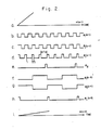
- the fr3quency f ccd /n of charge transfer in the serial register 14 is decreased in proportion to the zoom magnification factor n. Accordingly, the video signal emerging from the serial register 14 changes frequency f ccd /n whenever the zoom magnification factor n is changed.
- the video multiplexer 26 generate a video output signal of a constant frequency which is selected to be compatible with the video display electronics (not shown in FIG. 1). Somehow the frequency of the video output signal must be maintained constant for all values of n.
- a zoom integrator 50 comprising upper and lower level electrodes 50a, 50b is disposed over the substrate 12 at the output end of the serial register 14.
- n max the maximum achievable magnification factor of the focal zoom, in accordance with the relationship between n max and fed described previously in this specification.
- n may be any integer 1, 2, 3, ..., etc., up to n max , the value of n max depending upon the clock frequency food.
Landscapes
- Engineering & Computer Science (AREA)
- Multimedia (AREA)
- Signal Processing (AREA)
- Transforming Light Signals Into Electric Signals (AREA)
Claims (4)
dadurch gekennzeichnet,
Applications Claiming Priority (2)
| Application Number | Priority Date | Filing Date | Title |
|---|---|---|---|
| US06/331,505 US4442457A (en) | 1981-12-17 | 1981-12-17 | Charge coupled device focal zoom |
| US331505 | 1981-12-17 |
Publications (2)
| Publication Number | Publication Date |
|---|---|
| EP0082406A1 EP0082406A1 (de) | 1983-06-29 |
| EP0082406B1 true EP0082406B1 (de) | 1986-02-12 |
Family
ID=23294249
Family Applications (1)
| Application Number | Title | Priority Date | Filing Date |
|---|---|---|---|
| EP82111336A Expired EP0082406B1 (de) | 1981-12-17 | 1982-12-07 | Einrichtung mit Variooptik |
Country Status (6)
| Country | Link |
|---|---|
| US (1) | US4442457A (de) |
| EP (1) | EP0082406B1 (de) |
| JP (1) | JPS58150379A (de) |
| AU (1) | AU554540B2 (de) |
| DE (1) | DE3269110D1 (de) |
| IL (1) | IL67335A (de) |
Families Citing this family (19)
| Publication number | Priority date | Publication date | Assignee | Title |
|---|---|---|---|---|
| US4521804A (en) * | 1983-02-25 | 1985-06-04 | Rca Corporation | Solid-state color TV camera image size control |
| NL8501634A (nl) * | 1984-09-14 | 1986-04-01 | Philips Nv | Kamera voor televisie-, foto- respektievelijk filmopname uitgevoerd met een automatische fokusinstelinrichting. |
| EP0185485A3 (de) * | 1984-12-10 | 1988-03-16 | British Aerospace Public Limited Company | Überwachungsanlagen |
| FR2588709B1 (fr) * | 1985-10-16 | 1988-07-29 | Thomson Csf | Systeme de grossissement d'une partie d'une image dans les dispositifs de prise de vues video notamment a senseur a transfert de charges |
| JPH0644806B2 (ja) * | 1987-02-18 | 1994-06-08 | 三洋電機株式会社 | オ−トフオ−カス回路 |
| US4703179A (en) * | 1987-04-02 | 1987-10-27 | Ford Aerospace & Communications Corporation | Sensor for hemispherical applications |
| US4922346A (en) * | 1987-06-30 | 1990-05-01 | Sanyo Electric Co., Ltd. | Automatic focusing apparatus having a variable focusing speed and particularly suited for use with interlaced scanning |
| GB2207020B (en) * | 1987-07-08 | 1991-08-21 | Gec Avionics | Imaging system |
| JPS6449381A (en) * | 1987-08-20 | 1989-02-23 | Fuji Photo Film Co Ltd | Solid-state image pickup device |
| KR920003656B1 (ko) * | 1988-04-01 | 1992-05-06 | 샤프 가부시끼 가이샤 | 전자적으로 화상을 확대하여 촬영이 가능한 촬상 장치 |
| US6304987B1 (en) * | 1995-06-07 | 2001-10-16 | Texas Instruments Incorporated | Integrated test circuit |
| DE3938128C1 (de) * | 1989-11-16 | 1990-11-22 | Eltro Gmbh, Gesellschaft Fuer Strahlungstechnik, 6900 Heidelberg, De | |
| US5065024A (en) * | 1990-02-07 | 1991-11-12 | Inframetrics, Inc. | Infrared imaging system with simultaneously variable field of view and resolution and fixed optical magnification |
| US5173748A (en) * | 1991-12-05 | 1992-12-22 | Eastman Kodak Company | Scanning multichannel spectrometry using a charge-coupled device (CCD) in time-delay integration (TDI) mode |
| US5668887A (en) * | 1992-05-29 | 1997-09-16 | Eastman Kodak Company | Coating density analyzer and method using non-synchronous TDI camera |
| US5481300A (en) * | 1994-04-29 | 1996-01-02 | Motta; Ricardo J. | Image capture system |
| US7098949B2 (en) * | 2002-07-29 | 2006-08-29 | Hewlett-Packard Development Company, L.P. | Apparatus and method for improved-resolution digital zoom in a portable electronic imaging device |
| US7106526B2 (en) * | 2004-04-21 | 2006-09-12 | Matsushita Electric Industrial Co., Ltd. | Thin imaging apparatus, a thin camera, and an imaging method |
| AT505040B1 (de) | 2007-06-01 | 2008-10-15 | Jutz Lasertechnik Gmbh | Sicherheitseinrichtung für manuelle laserbearbeitungsvorrichtungen |
Family Cites Families (8)
| Publication number | Priority date | Publication date | Assignee | Title |
|---|---|---|---|---|
| US3781559A (en) * | 1972-06-19 | 1973-12-25 | Texas Instruments Inc | Variable field of view scanning system |
| JPS54128217A (en) * | 1978-03-29 | 1979-10-04 | Olympus Optical Co Ltd | Pickup device |
| NL7806503A (nl) * | 1978-06-16 | 1979-12-18 | Philips Nv | Inrichting voor twee-dimensionale aftasting. |
| GB2042304B (en) * | 1979-02-12 | 1983-09-28 | Rank Organisation Ltd | Optical scanning device |
| GB2048606B (en) * | 1979-02-28 | 1983-03-16 | Barr & Stroud Ltd | Optical scanning system |
| DE2936703A1 (de) * | 1979-09-11 | 1981-03-26 | Siemens AG, 1000 Berlin und 8000 München | Monolithisch integrierte schaltung mit einem zweidimensionalen bildsensor |
| JPS56132313A (en) * | 1980-03-19 | 1981-10-16 | Fuji Photo Film Co Ltd | Automatic focusing device |
| US4306252A (en) * | 1980-07-21 | 1981-12-15 | Eastman Kodak Company | Optical scanning method and apparatus |
-
1981
- 1981-12-17 US US06/331,505 patent/US4442457A/en not_active Expired - Lifetime
-
1982
- 1982-11-24 IL IL67335A patent/IL67335A/xx unknown
- 1982-12-07 DE DE8282111336T patent/DE3269110D1/de not_active Expired
- 1982-12-07 EP EP82111336A patent/EP0082406B1/de not_active Expired
- 1982-12-08 AU AU91348/82A patent/AU554540B2/en not_active Ceased
- 1982-12-17 JP JP57221721A patent/JPS58150379A/ja active Granted
Also Published As
| Publication number | Publication date |
|---|---|
| JPS58150379A (ja) | 1983-09-07 |
| US4442457A (en) | 1984-04-10 |
| EP0082406A1 (de) | 1983-06-29 |
| DE3269110D1 (en) | 1986-03-27 |
| AU554540B2 (en) | 1986-08-28 |
| IL67335A (en) | 1986-02-28 |
| AU9134882A (en) | 1983-06-23 |
| JPH0378833B2 (de) | 1991-12-16 |
Similar Documents
| Publication | Publication Date | Title |
|---|---|---|
| US4442457A (en) | Charge coupled device focal zoom | |
| US6005617A (en) | Electronic camera with mechanical subscanner | |
| CA2097179C (en) | Electro-optical imaging array with motion compensation | |
| EP0981245B1 (de) | Halbleiterbildaufnahmevorrichtung mit zur Fokusmessung und / oder zur Lichtstärkemessung bestimmten Wandlerzellen | |
| EP0374253A1 (de) | Dreidimensionale bildformungsanordnung | |
| US4521804A (en) | Solid-state color TV camera image size control | |
| EP0947091B1 (de) | System und verfahren zur bildbewegungskompensation eines ccd-bildsensors | |
| IL129778A (en) | Electro-optical reconnaissance system with forward motion compensation | |
| US20010043276A1 (en) | Imaging device including thinned read out mode and all pixel read out mode | |
| CA1200010A (en) | Solid state image sensing device | |
| US4499496A (en) | Solid state image sensing device | |
| US4314275A (en) | Infrared time delay with integration CTD imager | |
| US5646683A (en) | Imaging systems | |
| US20030052976A1 (en) | Imaging device an imaging method | |
| JPH02230600A (ja) | 双モード・イメージング装置 | |
| US4734773A (en) | Imaging apparatus having high-frequency electron purging circuit operable during an exposure time | |
| EP0599200B1 (de) | Festkörperbildaufnahmevorrichtung und Verfahren zu ihrem Betrieb | |
| EP1313308B1 (de) | Vorrichtung zur elektro-optischen fernerkundung mit bewegungskompensation | |
| JPH07264490A (ja) | 電荷結合撮像装置及びそのような電荷結合撮像装置を備える撮像器 | |
| JPH0377483A (ja) | 画振れ防止カメラ | |
| EP0066020B1 (de) | Infrarot-Detektorsystem mit Ladungsübertragungs-Sensoreinrichtung | |
| JP2617261B2 (ja) | 画素情報処理方法 | |
| USH1740H (en) | Synchronized rotating prism and CCD electrical readout color camera | |
| US4994919A (en) | Camera for recording television, photographic or cinematographic images, including an automatic focus-setting device | |
| JPH01151891A (ja) | カラー用固体撮像素子 |
Legal Events
| Date | Code | Title | Description |
|---|---|---|---|
| PUAI | Public reference made under article 153(3) epc to a published international application that has entered the european phase |
Free format text: ORIGINAL CODE: 0009012 |
|
| AK | Designated contracting states |
Designated state(s): DE FR GB IT NL SE |
|
| 17P | Request for examination filed |
Effective date: 19831221 |
|
| RAP1 | Party data changed (applicant data changed or rights of an application transferred) |
Owner name: HUGHES AIRCRAFT COMPANY |
|
| ITF | It: translation for a ep patent filed | ||
| GRAA | (expected) grant |
Free format text: ORIGINAL CODE: 0009210 |
|
| AK | Designated contracting states |
Designated state(s): DE FR GB IT NL SE |
|
| REF | Corresponds to: |
Ref document number: 3269110 Country of ref document: DE Date of ref document: 19860327 |
|
| ET | Fr: translation filed | ||
| PLBE | No opposition filed within time limit |
Free format text: ORIGINAL CODE: 0009261 |
|
| STAA | Information on the status of an ep patent application or granted ep patent |
Free format text: STATUS: NO OPPOSITION FILED WITHIN TIME LIMIT |
|
| 26N | No opposition filed | ||
| PGFP | Annual fee paid to national office [announced via postgrant information from national office to epo] |
Ref country code: FR Payment date: 19911107 Year of fee payment: 10 |
|
| PGFP | Annual fee paid to national office [announced via postgrant information from national office to epo] |
Ref country code: GB Payment date: 19911114 Year of fee payment: 10 |
|
| PGFP | Annual fee paid to national office [announced via postgrant information from national office to epo] |
Ref country code: SE Payment date: 19911120 Year of fee payment: 10 |
|
| PGFP | Annual fee paid to national office [announced via postgrant information from national office to epo] |
Ref country code: DE Payment date: 19911121 Year of fee payment: 10 |
|
| ITTA | It: last paid annual fee | ||
| PGFP | Annual fee paid to national office [announced via postgrant information from national office to epo] |
Ref country code: NL Payment date: 19911231 Year of fee payment: 10 |
|
| PG25 | Lapsed in a contracting state [announced via postgrant information from national office to epo] |
Ref country code: GB Effective date: 19921207 |
|
| PG25 | Lapsed in a contracting state [announced via postgrant information from national office to epo] |
Ref country code: SE Effective date: 19921208 |
|
| PG25 | Lapsed in a contracting state [announced via postgrant information from national office to epo] |
Ref country code: NL Effective date: 19930701 |
|
| GBPC | Gb: european patent ceased through non-payment of renewal fee |
Effective date: 19921207 |
|
| NLV4 | Nl: lapsed or anulled due to non-payment of the annual fee | ||
| PG25 | Lapsed in a contracting state [announced via postgrant information from national office to epo] |
Ref country code: FR Effective date: 19930831 |
|
| PG25 | Lapsed in a contracting state [announced via postgrant information from national office to epo] |
Ref country code: DE Effective date: 19930901 |
|
| REG | Reference to a national code |
Ref country code: FR Ref legal event code: ST |
|
| EUG | Se: european patent has lapsed |
Ref document number: 82111336.2 Effective date: 19930709 |