EP0082464A2 - Dispositif de développement à brosse magnétique - Google Patents
Dispositif de développement à brosse magnétique Download PDFInfo
- Publication number
- EP0082464A2 EP0082464A2 EP82111588A EP82111588A EP0082464A2 EP 0082464 A2 EP0082464 A2 EP 0082464A2 EP 82111588 A EP82111588 A EP 82111588A EP 82111588 A EP82111588 A EP 82111588A EP 0082464 A2 EP0082464 A2 EP 0082464A2
- Authority
- EP
- European Patent Office
- Prior art keywords
- development area
- development
- recording medium
- magnet arrangement
- magnetic brush
- Prior art date
- Legal status (The legal status is an assumption and is not a legal conclusion. Google has not performed a legal analysis and makes no representation as to the accuracy of the status listed.)
- Withdrawn
Links
Images


Classifications
-
- G—PHYSICS
- G03—PHOTOGRAPHY; CINEMATOGRAPHY; ANALOGOUS TECHNIQUES USING WAVES OTHER THAN OPTICAL WAVES; ELECTROGRAPHY; HOLOGRAPHY
- G03G—ELECTROGRAPHY; ELECTROPHOTOGRAPHY; MAGNETOGRAPHY
- G03G15/00—Apparatus for electrographic processes using a charge pattern
- G03G15/06—Apparatus for electrographic processes using a charge pattern for developing
- G03G15/08—Apparatus for electrographic processes using a charge pattern for developing using a solid developer, e.g. powder developer
- G03G15/09—Apparatus for electrographic processes using a charge pattern for developing using a solid developer, e.g. powder developer using magnetic brush
Definitions
- the invention relates to a device for magnetic brush development of electrostatic latent charge images on a sheet-shaped recording medium which is moved inside the device past a rotating cylinder arranged in a development area, which is charged with a magnetizable developer, and in the interior of which a fixed magnet arrangement for producing a brush-like distribution the developer particles are provided on the cylinder in the magnetic field causing the development area.
- the magnetic brush development of electrostatic latent charge images on sheet-like recording media is an image development without the use of a photoconductive intermediate image carrier.
- a sheet-shaped recording medium provided with a latent charge image is moved through the development area in a developing device, it arrives in the moving area of the magnetizable developer particles which project like bristles from the cylinder and move with it.
- the developer particles which reach the area of influence of the charge image are deposited directly on the recording medium. If the developer consists of two components, namely magnetizable carrier particles and small toner particles adhering to them electrostatically, as assumed in the following examples, only the toner particles are held on the charged areas of the recording medium.
- the magnetic brush consisting of bristle-like, magnetizable particles protruding from the cylinder is produced by the magnet arrangement held stationary in the interior of the cylinder, which usually consists of lengthways Direction of the cylinder extending permanent magnet. Because these permanent magnets are arranged in a fixed manner, the magnetic brush is only formed in a predetermined section on the circumference of the rotating cylinder.
- a magnetic brush cannot be formed in the development area during the time in which a single sheet is fed to the development area.
- the magnet arrangement becomes mechanical before the front edge of the respective single sheet arrives in the development area adjusted, which also changes the orientation of the magnetic field generated by it. If this magnetic field is no longer directed in such a way that bristle-like protruding magnetizable particles can accumulate in the development area on the circumference of the rotating cylinder, then no developer material is kept available in the development area and the described disadvantageous effect is avoided.
- the magnet arrangement can advantageously be rotated about an axis parallel to the cylinder longitudinal axis. This is the simplest way to change the orientation of the magnetic field generated by it, because by rotating it about the axis parallel to the cylinder longitudinal axis, the field lines of the magnetic field are pivoted by a relatively large angular amount on the circumference of the rotating cylinder with relatively slight movement.
- the magnet arrangement is rotated, for example, by means of an electromagnetically actuated pivot lever.
- a switch device which can be actuated by the recording medium for actuating the electromagnet is provided for a predetermined time, this time corresponding to the time required for moving the front edge of the recording medium into the development area.
- the switch device can thereby activate a time circuit whose output signal which is emitted for the predetermined time switches on the electromagnet.
- a switching transistor is then advantageously provided, which is controlled by the output signal of the timing circuit.
- a developing device 10 is shown in a cross section, the z. B. may belong to an electrostatic printer in which electrostatic latent images such. B. be applied in a character-like distribution at a recording station, not shown, on a sheet-shaped recording medium 11.
- This is introduced in the direction of arrow A shown in FIG. 1 coming from the recording station into the development device 10, moved through a development area B and then output again from the development device 10 at an output point C.
- the record carrier 11 before reaching the Development area B moves past a rocker 12 for actuating a switch device 13, passes between guide and transport rollers 14 and 15 and is then moved over a development housing 16 which is provided on its upper side with an opening 17 delimiting development area B.
- Guide surfaces 18 and 19 serve to hold down and guide the record carrier 11, but are not essential to the invention.
- the development housing 16 is approximately trough-shaped and is mounted between side boards of the development device 10, of which the board 20 can be seen in FIG. 1.
- a drive motor 21 for driving the movable elements of the developing device 10, not shown, is mounted on the circuit board 20.
- These movable elements are a screw conveyor 22 in a conveyor housing 24 provided with lower openings 23 and four rotatable cylinders 25, 26, 27 and 28.
- toner particles pass through the conveyor housing 24 in the longitudinal direction thereof, in FIG. 1 perpendicular to the plane of the drawing, are conveyed through them, they fall through the openings 23 distributed over the length of the conveyor housing 24 onto the rotating cylinder 25.
- Cylinders 26, 27 and 28 each rotate about a magnet arrangement 29, 30 and 31.
- Each magnet arrangement 29, 30 and 31 comprises two rod-shaped permanent magnets 29b fastened on a fixed support body 29a, 30a, 31a; 29c; 30b, 30c; 31b, 31c, which run in the longitudinal direction of each cylinder 26, 27, 28.
- the direction of the magnetic field generated with it is indicated by small arrows in FIG. 1 for each of these permanent magnets.
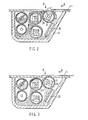
- a flow movement of an evenly distributed particle mixture essentially forms in the development housing 16, which is indicated schematically in the partial illustration according to FIG. 2 by arrows.
- the carrier particles and unused toner particles on the right side of the rotating cylinder 28 can fall down again and reach the region of guide channels which, like the rod-shaped permanent magnets and the rotating cylinders, extend over the entire length of the Development housing 16 are arranged.
- Such a guide channel 35 is shown in FIGS. 1, 2 and 3.
- the guide channels effect a uniform distribution and guiding of the material falling from the rotating cylinder 28 over the length of the development housing 16, so that it can be fed back evenly to the amount of material present in the lower part of the development housing 16.
- the record carrier 11 is shown without considering an adjustment of the magnet arrangement 31 so that it has just entered the development area B with its front edge.
- developer material 11 can be deposited in the development area B on the upward-facing surface of the recording medium and contaminate or falsify this rear side.
- the magnet arrangement 31 is brought from the operating position shown in FIG. 2 into the operating position shown in FIG. 3, as long as the front edge of the recording medium 11 moves towards and through the development area B.
- Fig. 3 shows that the Magnet arrangement 31 within the rotating cylinder 28 has been pivoted so far counterclockwise relative to the position shown in FIG. 2 that a magnetic brush can no longer form on the top of the cylinder 28.
- the mixture of carrier particles and toner particles which is transferred from the cylinder 27 to the cylinder 28, forms a magnetic brush on its lower left side, but not on its upper side in the development area B. In this way, it is possible to record the medium 11 in the direction of the arrow shown A over cylinder 28 until its leading edge has reached the left side of development area B.
- This position of the record carrier 11 is shown in broken lines in FIG. 3. If, at this moment, the magnet arrangement 31 is brought back into its position shown in FIG. 2, the latent charge image present on the underside of the recording medium 11 can be developed again, but without contamination of the back or top side of the recording medium 11.
- the developing device 10 is shown in a side view. It is not the side plate 20 that can be seen here, but the second side plate 20a, on the outside of which bearings 40, 41, 42 and 43 for the rotating cylinders 25, 26, 27 and 28 can be seen. Also shown is a filling cylinder 44 fastened to the outside of the circuit board 20a, which is shown partially broken and is used to fill in fresh toner material, which is transported by the screw conveyor 22 perpendicular to the plane of the drawing and reaches the interior of the development housing 16 in the manner described.
- an electromagnet 45 is also provided, the armature 46 of which is moved when switched on in the direction of the arrow E shown.
- the armature 46 is coupled to a two-armed lever 47, which is pretensioned at its lower end by a tension spring 48, which is anchored to the circuit board 20a at 49. If the armature 46 is moved in the direction of the arrow E when the electromagnet 45 is switched on, the lever 47 is pivoted about its bearing point 50 so that it reaches the position shown in dashed lines in FIG. 4. During this movement, it pivots with its upper end a pivoting lever 51 which is coupled to it and which is coupled to the axis of the magnet arrangement 31 which is arranged within the rotating cylinder 28.
- the magnet arrangement 31 is brought in the manner described in relation to its operating position shown in FIG. 2 into its position shown in FIG. 3, in which the formation of a magnetic brush on the top of the rotating cylinder 28 is not possible.
- Fig. 5 shows a simple electrical control circuit for actuating the electromagnet 45. This is connected in series with a switching transistor 60 to an operating voltage source + V , and a diode 61 is connected in parallel, which in a known manner the formation of overvoltages when the Prevents electromagnet 45.
- the switching transistor 60 is controlled at its base by the output signal of a timing circuit 62, which can be a monostable circuit, for example.
- the switching transistor 60 is controlled to be conductive for the duration of its output signal, which is supplied to the base via a voltage divider formed from resistors 63 and 64 and the electromagnet 45 turned on.
- the timer circuit 62 is in turn controlled by actuating the switch device 13 with which a control voltage + Vcc is switched on to its control input.
- the switch device 13 is shown in FIG. 1, and its actuation by the rocker 12 by means of the movement of the recording medium 11 has already been explained.
- the length of the output signal of the timer circuit 62 is dimensioned to correspond to the time it takes for the leading edge of the recording medium 11 to pass from the point at which it moves the rocker 12 to a point within the development area B, such as it is indicated in FIG. 3 for the dashed position of the record carrier 11.
Landscapes
- Physics & Mathematics (AREA)
- General Physics & Mathematics (AREA)
- Magnetic Brush Developing In Electrophotography (AREA)
Applications Claiming Priority (2)
| Application Number | Priority Date | Filing Date | Title |
|---|---|---|---|
| DE19813150329 DE3150329A1 (de) | 1981-12-18 | 1981-12-18 | Vorrichtung zur magnetbuerstenentwicklung |
| DE3150329 | 1981-12-18 |
Publications (2)
| Publication Number | Publication Date |
|---|---|
| EP0082464A2 true EP0082464A2 (fr) | 1983-06-29 |
| EP0082464A3 EP0082464A3 (fr) | 1983-08-03 |
Family
ID=6149163
Family Applications (1)
| Application Number | Title | Priority Date | Filing Date |
|---|---|---|---|
| EP82111588A Withdrawn EP0082464A3 (fr) | 1981-12-18 | 1982-12-14 | Dispositif de développement à brosse magnétique |
Country Status (3)
| Country | Link |
|---|---|
| EP (1) | EP0082464A3 (fr) |
| JP (1) | JPS58107561A (fr) |
| DE (1) | DE3150329A1 (fr) |
Cited By (1)
| Publication number | Priority date | Publication date | Assignee | Title |
|---|---|---|---|---|
| EP0092440A3 (en) * | 1982-04-20 | 1984-07-18 | Kanegafuchi Kagaku Kogyo Kabushiki Kaisha | Magnet roller |
Families Citing this family (1)
| Publication number | Priority date | Publication date | Assignee | Title |
|---|---|---|---|---|
| JP2530354Y2 (ja) * | 1990-12-20 | 1997-03-26 | 三菱農機株式会社 | 歩行型移植機における植付部動力の伝動構造 |
Family Cites Families (5)
| Publication number | Priority date | Publication date | Assignee | Title |
|---|---|---|---|---|
| US3145122A (en) * | 1962-08-13 | 1964-08-18 | Addressograph Multigraph | Apparatus for applying developer powder to photo-conductive insulating material |
| CH496263A (de) * | 1968-08-07 | 1970-09-15 | Rank Xerox Ltd | Verfahren und Vorrichtung zur Steuerung der Entwicklung von latenten elektrostatischen Bildern |
| JPS4969145A (fr) * | 1972-11-06 | 1974-07-04 | ||
| CH549824A (de) * | 1972-12-08 | 1974-05-31 | Turlabor Ag | Verfahren fuer die steuerung einer magnetischen buerste und vorrichtung zur ausfuehrung des verfahrens. |
| JPS52153448A (en) * | 1976-06-16 | 1977-12-20 | Fuji Xerox Co Ltd | Magnetic brush developing device |
-
1981
- 1981-12-18 DE DE19813150329 patent/DE3150329A1/de not_active Ceased
-
1982
- 1982-12-13 JP JP21714882A patent/JPS58107561A/ja active Pending
- 1982-12-14 EP EP82111588A patent/EP0082464A3/fr not_active Withdrawn
Cited By (1)
| Publication number | Priority date | Publication date | Assignee | Title |
|---|---|---|---|---|
| EP0092440A3 (en) * | 1982-04-20 | 1984-07-18 | Kanegafuchi Kagaku Kogyo Kabushiki Kaisha | Magnet roller |
Also Published As
| Publication number | Publication date |
|---|---|
| DE3150329A1 (de) | 1983-07-07 |
| JPS58107561A (ja) | 1983-06-27 |
| EP0082464A3 (fr) | 1983-08-03 |
Similar Documents
| Publication | Publication Date | Title |
|---|---|---|
| DE2411855C3 (de) | Einrichtung zum Steuern des Potentials der Entwicklerelektrode | |
| DE3854438T2 (de) | Elektrophotographisches Farbgerät. | |
| DE3411948C2 (fr) | ||
| DE69218751T2 (de) | Bilderzeugungsgerät | |
| DE1522689C3 (de) | Tonerspender mit automatischer Steuerung | |
| DE2626089C3 (de) | Elektrofotografisches Kopiergerät mit einer Reinigungseinrichtung | |
| DE2163531B2 (de) | Übertragungselektrode zur Kontaktübertragung von Tonerbildern | |
| DE2842516B2 (de) | Entwicklungseinrichtung für ein elektrophotographisches Kopiergerät | |
| DE2059805A1 (de) | Vorrichtung zur UEbertragung elektrostatisch geladener Tonerteilchen | |
| DE1572370A1 (de) | Vorrichtung zum automatischen Nachfuellen einer Toners in einer xerografischen Vervielfaeltigungsanlage | |
| DE2803200C2 (de) | Vorrichtung zur Entwicklung eines elektrostatischen Ladungsbildes | |
| DE3833302A1 (de) | Papiertransport fuer die elektrofotografische bilderzeugung | |
| DE3109214A1 (de) | Geraet zur entwicklung eines latenten elekrostatischen bildes | |
| DE3117238C2 (de) | Magnetbürstenanordnung in einer Entwicklungsvorrichtung zur Entwicklung von Ladungsbildern auf einem Ladungsbildträger | |
| DE2644529B2 (de) | Entwicklungsverfahren für elektrostatische Ladungsbilder | |
| DE2403186C3 (de) | Entwicklungsvorrichtung für ein elektrofotografisches Kopiergerät | |
| DE3129735C2 (de) | Bildaufzeichnungsgerät | |
| DE3436648C2 (fr) | ||
| EP0082464A2 (fr) | Dispositif de développement à brosse magnétique | |
| EP0946907B1 (fr) | Procede de fonctionnement d'une imprimante ou d'une photocopieuse electrographique comportant au moins deux unites de developpement | |
| DE2450145A1 (de) | Thermisch unempfindliche steuervorrichtung fuer eine partikelkonzentration | |
| DE2162517C3 (de) | Verfahren und Vorrichtung zur Herstellung eines Tonerbildes auf beiden Seiten eines Empfangsblattes | |
| DE2240551B2 (de) | Vorrichtung zum Entwickeln eines latenten, elektrostatischen, auf der fotoleitenden Oberfläche einer Platte aufgezeichneten Bildes | |
| DE1772254A1 (de) | Verfahren und Vorrichtung zur Herstellung von Kopien | |
| DE1472904B1 (de) | Vorrichtung zur Entwicklung des latenten elektrostatischen Ladungsbildes eines beschichteten Papiertraegers |
Legal Events
| Date | Code | Title | Description |
|---|---|---|---|
| PUAI | Public reference made under article 153(3) epc to a published international application that has entered the european phase |
Free format text: ORIGINAL CODE: 0009012 |
|
| PUAL | Search report despatched |
Free format text: ORIGINAL CODE: 0009013 |
|
| AK | Designated contracting states |
Designated state(s): CH DE FR GB IT LI SE |
|
| AK | Designated contracting states |
Designated state(s): CH DE FR GB IT LI SE |
|
| STAA | Information on the status of an ep patent application or granted ep patent |
Free format text: STATUS: THE APPLICATION IS DEEMED TO BE WITHDRAWN |
|
| 18D | Application deemed to be withdrawn |
Effective date: 19840404 |
|
| RIN1 | Information on inventor provided before grant (corrected) |
Inventor name: NOELLE, JUERGEN Inventor name: EHLERS, BERND Inventor name: SPIESS, LOTHAR Inventor name: ROTHGORDT, ULF, DR. Inventor name: MEHLHART, ERWIN Inventor name: FRANKE, THEODOR |