EP0082473A2 - Sender für Frequenzmodulation - Google Patents
Sender für Frequenzmodulation Download PDFInfo
- Publication number
- EP0082473A2 EP0082473A2 EP82111634A EP82111634A EP0082473A2 EP 0082473 A2 EP0082473 A2 EP 0082473A2 EP 82111634 A EP82111634 A EP 82111634A EP 82111634 A EP82111634 A EP 82111634A EP 0082473 A2 EP0082473 A2 EP 0082473A2
- Authority
- EP
- European Patent Office
- Prior art keywords
- frequency
- modulation
- transmitter
- controlled oscillator
- voltage controlled
- Prior art date
- Legal status (The legal status is an assumption and is not a legal conclusion. Google has not performed a legal analysis and makes no representation as to the accuracy of the status listed.)
- Ceased
Links
Images


Classifications
-
- H—ELECTRICITY
- H03—ELECTRONIC CIRCUITRY
- H03C—MODULATION
- H03C3/00—Angle modulation
- H03C3/02—Details
- H03C3/09—Modifications of modulator for regulating the mean frequency
- H03C3/0908—Modifications of modulator for regulating the mean frequency using a phase locked loop
- H03C3/0958—Modifications of modulator for regulating the mean frequency using a phase locked loop applying frequency modulation by varying the characteristics of the voltage controlled oscillator
-
- H—ELECTRICITY
- H03—ELECTRONIC CIRCUITRY
- H03C—MODULATION
- H03C2200/00—Indexing scheme relating to details of modulators or modulation methods covered by H03C
- H03C2200/0037—Functional aspects of modulators
- H03C2200/005—Modulation sensitivity
Definitions
- This invention generally relates to a transmitter/receiver and more particularly.to an improvement in a frequency modulation (hereinafter referred to as FM) radio transmitter having a digital frequency synthesizer.
- FM frequency modulation
- a voltage controlled oscillator serving as an oscillator of the frequency synthesizer in this type of FM transmitter has a non-linear output oscillation frequency characteristic with respect to the VCO control voltage applied to the control terminal of the VCO, owing to a non-linear characteristic of a voltage-dependent variable capacitor and other non-linear factors, though the output oscillation frequency characteristic should ideally be linear.
- the modulation sensitivity level varies with the oscillation frequency of the VCO, though the modulation sensitivity level should ideally remain unchanged relative to the VCO oscillation frequency.
- the modulation sensitivity level is varied corresponding to the center frequency.
- modulation sensitivity level decreases as the VCO oscillation frequency increases, modulation will be deeper for low transmission carrier frequencies and shallower for high carrier frequencies even when the level of the low frequency signal applied as the modulation signal to the modulation signal input terminal of the VCO is fixed.
- An object of the invention is to provide an improved FM radio transmitter incorporating a digital frequency synthesizer capable of making FM modulation sensitivity uniform.
- a frequency modulation transmitter comprising: a transmitter section; a frequency synthesizer for operating the transmitter section including a loop connection of a voltage controlled oscillator, a frequency divider for frequency dividing the output signal of the voltage controlled oscillator and a comparator for comparing the output signal of the frequency divider with a reference frequency signal, and a channel controller for generating channel designation information for setting the frequency division ratio of the frequency divider; and means for applying a modulation input signal to the voltage controlled oscillator, characterized by means for setting the level of the modulation input signal according to the frequency division ratio of the frequency divider.
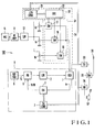
- a VCO 1 generates an output signal fv led to a frequency divider 2.
- a reference signal generator 6 generates a reference signal fR led to the other input terminal of the phase detector 5.
- the output signal of the phase detector 5 is coupled through a low-pass filter 7 to a control termial of the VCO 1.
- a frequency synthesizer 8 is constituted by the above-mentioned components.
- a microphone 11 produces an audio signal fed to an audio frequency amplifier 12, the output signal of which is in turn fed to a low-pass filter 13.
- the output signal of the low-pass filter 13 is coupled through a potentiometer section comprised of variable resistors 14 to 16 connected in parallel and an analog switch section 31 comprised of analog switches 17 to 19 to a modulation signal input terminal of the VCO 1.
- the variable resistors 14 to 16 constitute respective potentiometers grounded at one end and the signal level passing through the potentiometer is variable.
- the potentiometer section changes the level of the modulation input signal to provide three different levels.
- the analog switches 17 to 19 are controlled by a second output signal of the /means channel controller 3 through decoder 32 comprised of a level converter 21 and a decoder 22.
- the output signal of the VCO 1 is applied to operate a transmitter section 33 and a receiver section 34.
- a switch 35 is transferred to the transmitter section 33, a radio frequency signal generated by the transmitter section 33 is transmitted from an antenna 36.
- a radio frequency signal caught by the antenna 36 is processed by the receiver section 34 to drive a loudspeaker 37.
- the frequency divider 2 divides a signal fv generated from the VCO 1 to provide a frequency fv/N.
- the frequency division ratio 1/N is set by a channel designation signal from the 5 channel controller 3.
- the phase detector provides an error signal which is proportional to the phase difference between the frequency division signal fv/N and a reference signal fR from the reference signal generator 6.
- the error signal is supplied to a control terminal of the VCO 1 through the LPF 7.
- the output frequency of the VCO 1 is determined according to the channel designation signal.
- an audio signal from the microphone 11 is amplified by the audio frequency amplifier 12, and only a necessary audible frequency band signal is passed through the low-pass filter 13 and converted to signals of predetermined levels through the potentiometers comprised of the variable resistors 14 to 16.
- the analog switches 17 to 19, to which the output signals of the respective potentiometers are supplied, are controlled according to the second output responsive to the channel designation data from the channel controller 3. More particularly, the channel controller 3 also generates, in response to the channel designation data standing for the first output signal, second output signals in the form of code signals representative of a plurality of sub-frequency bands within a transmission frequency band in use.
- the code signals are decoded into corresponding analog signals by /means the decoder 32.
- Each of the analog signals actuates each of the analog switches 17 to 19 for transmission of one of the different levels of the modulation input signal.
- the transmission frequency band is divided into a plurality of, three, for example, divisions, and the output signal of one of the variable resistors 14 to 16 corresponding to the channel designation data is supplied as a modulation signal to the modulation signal input terminal of the VCO 1.
- a substantially uniform modulation sensitivity can be obtained even in the case of a wide band as shown in Fig. 4.
- the solid plot represents the modulation sensitivity characteristic in the individual sub-frequency bands or oscillation frequecy regions
- the dashed plot represents the ideal characteristic. It will be appreciated that the relation between the VCO oscillation frequency and modulation sensitivity level as shown at a solid curve in Fig. 3 obtained with a conventional frequency modulation transmitter based on the V CO control voltage versus VCO oscillation frequency characteristic as shown at a solid curve in Fig. 2 can be improved to a great extent according to the foregoing embodiment. In Figs. 2 and 3, a dotted line represents ideal characteristic.
- the modulation input terminal of the frequency synthesizer is provided on the VCO 1, it may be provided at any point in the loop.
- a one-chip IC analog multiplexer 24 for example ⁇ PD 4051BC, 4052BC or 4053BC manufactured by Nippon Electric Co., Ltd., which includes the level converter 21, decoder 22 and analog switches 17 to 19, may be used.
- the oscillation frequency band of the VCO is divided into three divisions, this is by no means limitative. In general, variable resistors and analog switches are necessary in number corresponding to the number of divisions.
- Fig. 5 is a block diagram showing an essential part of a second embodiment of the invention. This embodiment is different from the first embodiment of Fig. 1 in that the second output signals in response to the channel designation data from the channel controller 3 are led to a control terminal of an automatic gain control circuit 26 and the output thereof is led to the control terminal of the low frequency amplifier 12.
- the second output signals from the channel controller 3 may also be representative of sub-frequency bands within the transmission frequency band.
- the output of the microphone 11 is coupled through the audio frequency amplifier 12 to the low-pass filter 13. This output is supplied to the modulation input terminal of the VCO 1.
- the second output signals of the channel controller 3 are led to the control terminal of the automatic gain control circuit 26.
- Fig. 5 is the same as the first embodiment of Fig. 1, and like parts designate like parts.
- the oscillation frequency of the VCO 1 is controlled with the frequency division ratio 1/N controlled according to the channel designation data from the channel controller 3.
- the gain of the audio frequency amplifier 12 is controlled by the automatic gain control circuit 26 according to the second output signals in resonse to the channel designation data.
- the audio signal level from the microphone 11 is controlled according to the channel designation data, and the result is supplied to the modulation input terminal of the VCO 1.
- variations of the modulation sensitivity with the oscillation frequency of the VCO can be compensated for.
- modulation input terminal may not be provided on VCO 1 but may be provided at any point in the loop.
- the channel designation data are used to control the oscillation frequency of the V CO and also to control the modulation signal level for providing the modulation input.
- the FM modulation can be obtained directly without use of any compensating circuit such as an oscillator or a mixer, so that it is possible to simplify the circuit construction.
Landscapes
- Transmitters (AREA)
Applications Claiming Priority (2)
| Application Number | Priority Date | Filing Date | Title |
|---|---|---|---|
| JP204979/81 | 1981-12-17 | ||
| JP56204979A JPS58105631A (ja) | 1981-12-17 | 1981-12-17 | 周波数変調送信機 |
Publications (2)
| Publication Number | Publication Date |
|---|---|
| EP0082473A2 true EP0082473A2 (de) | 1983-06-29 |
| EP0082473A3 EP0082473A3 (de) | 1983-10-12 |
Family
ID=16499455
Family Applications (1)
| Application Number | Title | Priority Date | Filing Date |
|---|---|---|---|
| EP82111634A Ceased EP0082473A3 (de) | 1981-12-17 | 1982-12-15 | Sender für Frequenzmodulation |
Country Status (5)
| Country | Link |
|---|---|
| US (1) | US4501019A (de) |
| EP (1) | EP0082473A3 (de) |
| JP (1) | JPS58105631A (de) |
| AU (1) | AU565631B2 (de) |
| CA (1) | CA1201171A (de) |
Cited By (3)
| Publication number | Priority date | Publication date | Assignee | Title |
|---|---|---|---|---|
| EP0322139A3 (en) * | 1987-12-23 | 1990-04-04 | Marconi Instruments Limited | Frequency or phase modulation |
| EP0438260A3 (en) * | 1990-01-19 | 1991-10-30 | Motorola, Inc. | Capacitor precharge for reduced synthesizer lock time |
| EP0766375A1 (de) * | 1995-09-26 | 1997-04-02 | Robert Bosch Gmbh | Spannungsgesteuerter Oszillator |
Families Citing this family (12)
| Publication number | Priority date | Publication date | Assignee | Title |
|---|---|---|---|---|
| US4660182A (en) * | 1984-06-20 | 1987-04-21 | The Unites States Of America As Represented By The Secretary Of The Navy | Programmable multichannel sonobuoy transmitter |
| JPS61156310U (de) * | 1985-03-20 | 1986-09-27 | ||
| JPS6398770U (de) * | 1986-12-18 | 1988-06-27 | ||
| JPS63171036U (de) * | 1987-04-24 | 1988-11-08 | ||
| JPH0250606A (ja) * | 1988-08-12 | 1990-02-20 | Nec Corp | 周波数シンセサイザ |
| US5299264A (en) * | 1991-08-21 | 1994-03-29 | L. S. Research, Inc. | System for short-range transmission of signals over the air using a high frequency carrier |
| US5491839A (en) * | 1991-08-21 | 1996-02-13 | L. S. Research, Inc. | System for short range transmission of a plurality of signals simultaneously over the air using high frequency carriers |
| US5673323A (en) * | 1995-04-12 | 1997-09-30 | L. S. Research, Inc. | Analog spread spectrum wireless speaker system |
| US6529712B1 (en) * | 1999-08-25 | 2003-03-04 | Conexant Systems, Inc. | System and method for amplifying a cellular radio signal |
| JP2006140582A (ja) * | 2004-11-10 | 2006-06-01 | Matsushita Electric Ind Co Ltd | 送信信号生成装置 |
| CN101877588B (zh) | 2005-12-06 | 2012-05-30 | 罗姆股份有限公司 | 调频器以及使用该调频器的调频发送电路 |
| US20250306157A1 (en) * | 2024-03-29 | 2025-10-02 | United States Of America, As Represented By The Secretary Of The Navy | Remote Electronic Field Monitor |
Family Cites Families (6)
| Publication number | Priority date | Publication date | Assignee | Title |
|---|---|---|---|---|
| US4189689A (en) * | 1977-06-30 | 1980-02-19 | Wulfsberg Electronics, Inc. | Automatic leveling stabilized VHF-FM frequency synthesizer |
| GB2031676B (en) * | 1978-09-02 | 1983-05-11 | Marconi Instruments Ltd | Frequency modulation systems |
| GB2045556B (en) * | 1979-03-06 | 1983-08-03 | Racal Dana Instr Ltd | Frequency synthesizers |
| JPS57500761A (de) * | 1980-05-01 | 1982-04-30 | ||
| US4313209A (en) * | 1980-07-14 | 1982-01-26 | John Fluke Mfg. Co., Inc. | Phase-locked loop frequency synthesizer including compensated phase and frequency modulation |
| US4321706A (en) * | 1980-07-14 | 1982-03-23 | John Fluke Mfg. Co., Inc. | Frequency modulated phase-locked loop signal source |
-
1981
- 1981-12-17 JP JP56204979A patent/JPS58105631A/ja active Granted
-
1982
- 1982-12-15 EP EP82111634A patent/EP0082473A3/de not_active Ceased
- 1982-12-16 AU AU91608/82A patent/AU565631B2/en not_active Expired
- 1982-12-17 US US06/450,787 patent/US4501019A/en not_active Expired - Lifetime
- 1982-12-17 CA CA000418009A patent/CA1201171A/en not_active Expired
Cited By (3)
| Publication number | Priority date | Publication date | Assignee | Title |
|---|---|---|---|---|
| EP0322139A3 (en) * | 1987-12-23 | 1990-04-04 | Marconi Instruments Limited | Frequency or phase modulation |
| EP0438260A3 (en) * | 1990-01-19 | 1991-10-30 | Motorola, Inc. | Capacitor precharge for reduced synthesizer lock time |
| EP0766375A1 (de) * | 1995-09-26 | 1997-04-02 | Robert Bosch Gmbh | Spannungsgesteuerter Oszillator |
Also Published As
| Publication number | Publication date |
|---|---|
| US4501019A (en) | 1985-02-19 |
| CA1201171A (en) | 1986-02-25 |
| AU565631B2 (en) | 1987-09-24 |
| JPS6224974B2 (de) | 1987-06-01 |
| EP0082473A3 (de) | 1983-10-12 |
| AU9160882A (en) | 1983-06-23 |
| JPS58105631A (ja) | 1983-06-23 |
Similar Documents
| Publication | Publication Date | Title |
|---|---|---|
| US4501019A (en) | Frequency modulation transmitter | |
| US3983484A (en) | Multichannel signal transmitting and receiving apparatus | |
| US4132951A (en) | Digital processor controlled radio system | |
| US5430890A (en) | Radio receiver for mobile reception with sampling rate oscillator frequency being an integer-number multiple of reference oscillation frequency | |
| US4135158A (en) | Universal automotive electronic radio | |
| US4027242A (en) | Double superheterodyne multichannel receiver with a phase-locked loop frequency synthesizer | |
| US4061973A (en) | Synthesizer | |
| US4211975A (en) | Local signal generation arrangement | |
| US4520474A (en) | Duplex communication transceiver with modulation cancellation | |
| US5832375A (en) | Superheterodyne radio receiver | |
| GB2194696A (en) | Digital radio communications devices | |
| GB2278511A (en) | Frequency synthesizers | |
| WO1997035381A1 (en) | Reducing or eliminating radio transmitter mixer spurious outputs | |
| US4618997A (en) | Portable transceiver | |
| EP0089649B1 (de) | Funksender/-empfänger | |
| US4268915A (en) | Universal automotive electronic radio with display for tuning or time information | |
| US4449250A (en) | Radio-frequency synthesizer for duplex radios | |
| US4097805A (en) | Frequency-synthesizer type transceiver | |
| EP0456099B1 (de) | Frequenzdemodulator für Frequenzsprungbetrieb mit Kanälen | |
| US4494090A (en) | Frequency modulation system for a frequency synthesizer | |
| EP0221189A1 (de) | Elektronisch synchronisierbarer fm-empfänger | |
| US5281930A (en) | Frequency modulator | |
| JP2004518382A (ja) | 2点変調を有するトランシーバのトリミング法 | |
| US4097816A (en) | Tuning system | |
| US4095190A (en) | Tuning system |
Legal Events
| Date | Code | Title | Description |
|---|---|---|---|
| PUAI | Public reference made under article 153(3) epc to a published international application that has entered the european phase |
Free format text: ORIGINAL CODE: 0009012 |
|
| AK | Designated contracting states |
Designated state(s): DE FR GB |
|
| PUAL | Search report despatched |
Free format text: ORIGINAL CODE: 0009013 |
|
| AK | Designated contracting states |
Designated state(s): DE FR GB |
|
| RAP1 | Party data changed (applicant data changed or rights of an application transferred) |
Owner name: NEC CORPORATION |
|
| 17P | Request for examination filed |
Effective date: 19831214 |
|
| STAA | Information on the status of an ep patent application or granted ep patent |
Free format text: STATUS: THE APPLICATION HAS BEEN REFUSED |
|
| 18R | Application refused |
Effective date: 19881121 |
|
| R18R | Application refused (corrected) |
Effective date: 19881011 |
|
| APAF | Appeal reference modified |
Free format text: ORIGINAL CODE: EPIDOSCREFNE |
|
| RIN1 | Information on inventor provided before grant (corrected) |
Inventor name: FUKUMURA, YUKIO Inventor name: MATSUKURA, MASAYUKI |