EP0082622B1 - Wirbelbett-Verbrennungsapparat und Verfahren zur Durchführung der Wirbelbettverbrennung - Google Patents
Wirbelbett-Verbrennungsapparat und Verfahren zur Durchführung der Wirbelbettverbrennung Download PDFInfo
- Publication number
- EP0082622B1 EP0082622B1 EP82306415A EP82306415A EP0082622B1 EP 0082622 B1 EP0082622 B1 EP 0082622B1 EP 82306415 A EP82306415 A EP 82306415A EP 82306415 A EP82306415 A EP 82306415A EP 0082622 B1 EP0082622 B1 EP 0082622B1
- Authority
- EP
- European Patent Office
- Prior art keywords
- fluidized bed
- particles
- particulate matter
- bed
- heat exchange
- Prior art date
- Legal status (The legal status is an assumption and is not a legal conclusion. Google has not performed a legal analysis and makes no representation as to the accuracy of the status listed.)
- Expired
Links
Images


Classifications
-
- F—MECHANICAL ENGINEERING; LIGHTING; HEATING; WEAPONS; BLASTING
- F23—COMBUSTION APPARATUS; COMBUSTION PROCESSES
- F23C—METHODS OR APPARATUS FOR COMBUSTION USING FLUID FUEL OR SOLID FUEL SUSPENDED IN A CARRIER GAS OR AIR
- F23C10/00—Fluidised bed combustion apparatus
- F23C10/02—Fluidised bed combustion apparatus with means specially adapted for achieving or promoting a circulating movement of particles within the bed or for a recirculation of particles entrained from the bed
-
- B—PERFORMING OPERATIONS; TRANSPORTING
- B01—PHYSICAL OR CHEMICAL PROCESSES OR APPARATUS IN GENERAL
- B01J—CHEMICAL OR PHYSICAL PROCESSES, e.g. CATALYSIS OR COLLOID CHEMISTRY; THEIR RELEVANT APPARATUS
- B01J8/00—Chemical or physical processes in general, conducted in the presence of fluids and solid particles; Apparatus for such processes
- B01J8/18—Chemical or physical processes in general, conducted in the presence of fluids and solid particles; Apparatus for such processes with fluidised particles
- B01J8/24—Chemical or physical processes in general, conducted in the presence of fluids and solid particles; Apparatus for such processes with fluidised particles according to "fluidised-bed" technique
- B01J8/32—Chemical or physical processes in general, conducted in the presence of fluids and solid particles; Apparatus for such processes with fluidised particles according to "fluidised-bed" technique with introduction into the fluidised bed of more than one kind of moving particles
-
- B—PERFORMING OPERATIONS; TRANSPORTING
- B01—PHYSICAL OR CHEMICAL PROCESSES OR APPARATUS IN GENERAL
- B01J—CHEMICAL OR PHYSICAL PROCESSES, e.g. CATALYSIS OR COLLOID CHEMISTRY; THEIR RELEVANT APPARATUS
- B01J8/00—Chemical or physical processes in general, conducted in the presence of fluids and solid particles; Apparatus for such processes
- B01J8/18—Chemical or physical processes in general, conducted in the presence of fluids and solid particles; Apparatus for such processes with fluidised particles
- B01J8/24—Chemical or physical processes in general, conducted in the presence of fluids and solid particles; Apparatus for such processes with fluidised particles according to "fluidised-bed" technique
- B01J8/38—Chemical or physical processes in general, conducted in the presence of fluids and solid particles; Apparatus for such processes with fluidised particles according to "fluidised-bed" technique with fluidised bed containing a rotatable device or being subject to rotation or to a circulatory movement, i.e. leaving a vessel and subsequently re-entering it
- B01J8/384—Chemical or physical processes in general, conducted in the presence of fluids and solid particles; Apparatus for such processes with fluidised particles according to "fluidised-bed" technique with fluidised bed containing a rotatable device or being subject to rotation or to a circulatory movement, i.e. leaving a vessel and subsequently re-entering it being subject to a circulatory movement only
-
- F—MECHANICAL ENGINEERING; LIGHTING; HEATING; WEAPONS; BLASTING
- F22—STEAM GENERATION
- F22B—METHODS OF STEAM GENERATION; STEAM BOILERS
- F22B31/00—Modifications of boiler construction, or of tube systems, dependent on installation of combustion apparatus; Arrangements or dispositions of combustion apparatus
- F22B31/0007—Modifications of boiler construction, or of tube systems, dependent on installation of combustion apparatus; Arrangements or dispositions of combustion apparatus with combustion in a fluidized bed
- F22B31/0084—Modifications of boiler construction, or of tube systems, dependent on installation of combustion apparatus; Arrangements or dispositions of combustion apparatus with combustion in a fluidized bed with recirculation of separated solids or with cooling of the bed particles outside the combustion bed
Definitions
- the present invention relates generally to fluidized bed combustion and, more particularly, to certain new and useful improvements in fluidized bed combustion devices and methods for carrying out fluidized bed combustion.
- Fluidized bed combustion is currently one of the most promising technologies for advances in the field of combustion furnaces, boilers, incinerators, etc., particularly in these days of ex- horbitant energy costs and restrictive environmental protection regulations.
- a significant reason that fluidized bed combustion holds such promise is my previous invention described in detail in my U.S. Patent No. 4,240,377 granted December 23, 1980 the disclosure of which is hereby incorporated by reference herein.
- fluidized bed combustion permits the use of a wide range of solid, liquid and gaseous fuels, while at the same time reducing pollutants such as nitrous oxide and sulfur dioxide, and providing high combustion and heat exchange efficiencies when compared with conventional combustion techniques.
- This invention of my'377 patent enables higher combustion and heat exchange efficiencies than previously known fluidized bed combustion devices. Furthermore, it provides several control points to permit immediate variation of steam generating capacity.
- a significant drawback to conventional fluidized bed combustion devices is that limestone and ash must be removed from the combustion bed to maintain an equilibrium of reactivity within the bed. Such removal is usually done by "purging" the bed - i.e., by a continuous process of physically removing bed constituents from the bed for disposal. This results in loss of the heat from the combustion zone as well as unreacted fuel and limestone particles. It also presents a significant disposal problem since dumping can contaminate the aquifer.
- the efficiency of combustion can be enhanced by increasing the amount of movement, or circulation, of the bed particles.
- the greater the circulation of bed constituents within the burning zone the more efficient the combustion of fuel particles and the greater the reaction to reduce sulfur dioxide.
- a fluidized bed combustion apparatus such as that described in my '377 patent, having a combustion chamber adapted to provide a fluidized bed of particulate matter, including combustible fuel particles, generally supported on a support member adapted to permit introduction of a fluidizing gas medium into the particulate matter and an inlet for introducing at least fresh combustible fuel particles into the fluidized bed, heat exchange means generally separated from the fluidized bed, said heat exchange means including communicating up-flow and down-flow portions for permitting circulation of particulate matter from the fluidized bed, through said heat exchange means and back into the fluidized bed, said down flow portion having a discharge outlet opening to the combustion chamber which discharge outlet is arranged to direct particulate matter passing down the down-flow portion in a generally horizontal direction over the fluidized bed and withdrawal means for withdrawing some of the particulate matter from the fluidized bed and introducing withdrawn particulate matter into said up-flow portion of said heat exchange means, I cause, by my present invention, the location or locations at which the withdrawn particulate matter is
- my invention provides a method of carrying out fluidized bed combustion and transfer of heat generated from combustion of the fluidized bed, comprising the steps of providing for withdrawal of some particulate matter from the fluidized bed and causing the withdrawn particulate matter to flow through heat exchange means generally separated from the fluidized bed and back to the fluidized bed, characterised in that said particulate matter is withdrawn from the fluidized bed at a location generally laterally spaced from where the withdrawn particulate matter is discharged from the heat exchange means and in that the withdrawn particulate matter leaving the heat exchange means is discharged in a generally horizontal direction over the fluidized bed, the arrangement being such that particulate matter discharged from the heat exchange means is generally unaffected by the withdrawal of particulate matter and provides circulatory movement of the fluidized bed.
- the bed constituents circulating from the fluidized combustion bed and through the heat exchange means are advantageously discharged back into the bed in such a manner as to generate relatively high velocity flow of returning particles and establish a high degree of circulation within the burning zone, i.e. the combustion bed.
- the heat exchange means is vertically extending, with an upward flow portion and a downward flow portion which discharges the circulating particles back into the bed.
- the discharge end of the downward flow portion is preferably arched to direct the returning bed constituents in a generally horizontal direction and is located directly over a portion of the combustion bed (rather than over a quiescent zone).
- the inlet for introduction of fresh fuel (and, preferably, fine limestone particles as well) is preferably located somewhere just below the arched discharge channel of the downward flow heat exchange means to join the horizontal discharge flow of particles for enhancing the flow velocity of the returning particles.
- a portion of the combustion chamber generally opposite the arched discharge channel is provided with a sloped wall segment to enhance circulation within the bed by preventing any tendency of the circulating particles to collect in a "dead corner.”
- the solids act as a grinding agent for both the limestone particles and the fuel particles in the bed.
- they continuously expose fresh surface area of the limestone to react with sulfur dioxide, providing for continuous removal of the sulfur gas. They also reduce the size of the ash particles to permit removal of spent fuel at the dust collection flue gas exit and grind ash from the surface of the fuel particles.
- the "cascade" of these bead-like particles returning from the down-flow portion of the heat exchange means serves to return some of the particles entrained in the flue gas back to the combustion bed.
- a particularly useful advantage of the combined use of the inert bead-like particles and fresh limestone is that there is no need to "purge” the combustion bed to remove partially sulfated limetone because the sulfated surface of the limestone is continuously ground away by the bead-like particles. Thus, there is no need to maintain a continuous withdrawal of the bed constituents and risk losing good fuel particles, unspent limestone particles or the heat contained in these particles. In addition, there are no significant handling problems, as the fully spent fuel and limestone (both in the form of dust-like ash particles) can be removed in the "bag house” after their heat has been transferred to steam generating surfaces.
- the returning bed constituents are discharged into a generally horizontal direction to provide a circulatory influence on the combustion bed.
- the force of injecting these fresh particles combines with the momentum of horizontally discharged particles from the heat exchanger to enhance the distribution of the fuel/ limestone and the circulatory influence on the combustion bed.
- the boiler 10 is formed with vessel walls having heat exchange tubes generally interconnected by webbing generally as described in my aforesaid '377 patent.
- vessel walls having heat exchange tubes generally interconnected by webbing generally as described in my aforesaid '377 patent.
- the floor 14 of the boiler chamber is adapted to introduce an oxygen-containing fluidizing gas
- the combustion chamber floor 14 includes gas introduction means in the form of a plurality of nozzles 18 formed on distributor plate 20 which is positioned on top of air plenum chambers 22 to form the floor of the combustion vessel.
- the plenum chambers are coupled to a source (not shown) of the fluidizing air in any conventional manner and nozzles 18 are of the bubble-cap type.
- evaporator screen tubes below the bed are located evaporator screen tubes (described hereinafter) and, above them, a set of superheater heat exchange tubes (indicated generally at 24) for super heating the heat exchange medium (usually a fluid such as water) and economizer tubes (indicated at 26) for initial preheating of the heat exchange medium by the rising flue gases and particles entrained therein.
- a set of superheater heat exchange tubes indicated generally at 24 for super heating the heat exchange medium (usually a fluid such as water)
- economizer tubes indicated at 26 for initial preheating of the heat exchange medium by the rising flue gases and particles entrained therein. It will be understood that any other desired heat exchange tube arrangements can be utilized above the combustion bed.
- a gas-solids separator (here a cyclone separator) 28 is coupled (by conduit 29) to the boiler vessel 10 for removing any unspent bed particles which may be entrained in the flue gas rising from the bed and returning them to the fluidized combustion bed.
- separator 28 is coupled to reintroduction conduit 30 which discharges the separated out particles back into the fluidized bed, and an outlet 32 which leads the essentially particle-free flue gas to the exhaust stack or other flue gas exit of the facility.
- the cyclone treated gas should be subjected to a final "cleansing" action, such as passing through a "bag house”, to filter out these superfine particles before expelling the flue gas into the atmosphere.
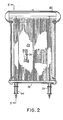
- the fluidized bed combustion boiler also includes an inlet 54 (two are shown in Figure 2) for introducing fresh fuel and, as an aspect of the invention described below, finely divided particles of limestone.
- the walls of heat exchange tubes are coupled to various headers such as header segments 36 and 40 along the front and back chamber walls and header segments 42-45 along the vessel side walls, as well as steam- water separator boiler drum 46 at the top of the boiler.
- Another water header 38 is formed along the bottom inside of each upward flow heat exchange chamber segment, described more fully below.
- a solids recirculation system is utilized similar to my aforesaid '377 patent.
- There is at least one quiescent zone i.e., an area free of direct influence by the fluidizing gas
- Each withdrawal member 48 is coupled by suitable conduit members (indicated generally at 52) to the base portion 54 of a vertically extending heat exchange chamber 56 which is generally like that disclosed in my aforesaid '377 patent.
- the base 54 of each vertical heat exchange chamber 56 preferably includes means for introducing air or a like oxygen containing gas for upward flow through the heat exchange chamber, and may include valve means (such as butterfly valves 58) for controlling the flow of solids through the heat exchanger, for the same purposes disclosed in my aforesaid '377 patent.
- the withdrawal conduit 52 may provide a generally U-shaped duct (as disclosed in my'377 patent) or it may generally form a more Y-shaped configuration with the base 54 of the vertical heat exchanger, as shown in Figure 5.
- the upward-flow portion 56 of each vertical heat exchanger more-or-less extends along the exterior sides of the boiler vessel as best shown in Figures 3 and 5.
- the top of the upward-flow heat exchange chamber 56 opens into a downward-flow heat exchange chamber 60 (by an intermediate segment 62), much like my '377 patent.
- the downward-flow heat exchange chamber 60 extends along essentially the entire width of front wall 12a of the boiler vessel as shown in Figure 1.
- the up-flow portion 56 and the down flow portion 60 are formed primarily by walls of heat exchange tubes like those disclosed in my '377 patent. It will be understood that intermediate walls of heat exchange tubes can be placed within the down flow chamber 60 to form a plurality of smaller chambers for additional heat exchange surface area, similar to my '377 patent.
- the bottom, or discharge, portion (64) of down-flow chamber 60 includes an arched portion providing a "slide" adapted to discharge particles in a generally horizontal direction.
- the lower "slide” portion of arch 64 is formed of the same webbed heat exchange tubes as segments 56 and 60, while the upper portion (indicated at 66 and comprising evaporator screen tubes) which extends directly over the bed should have openings or spaces between the heat exchange tubes to permit upward flow of flue gases yet act as another impingement barrier for particles entrained in the flue gases.
- the arched discharge duct 64 is on the same wall as fuel/limestone inlet 34 which is advantageously located just below the arched duct 64 and oriented to inject the fresh fuel particles (and limestone) in a generally horizontal direction to add momentum to the horizontal flow of discharged particles from arched duct 64.
- a portion of the vessel containing wall opposite arched discharge duct 64 i.e., back wall 12c is sloped (as indicated at 70) towards the arched discharge duct to further enhance circulation of the constituents of the bed and at the same time reduce the expensive grid area for distributing air.
- sloped wall 70 is at an angle of from about 45° to about 75° (and preferably about 60°) with respect to the combustion chamber floor.
- the top of sloped wall 70 is just below the outlet of cyclone return duct 30 which, in turn, is somewhat below the arched discharge duct 64 so that the discharge flow from return duct 30 is very roughly tangential to the circulatory flow (indicated in Figure 1 by spiral-like lines 72) generated by the returning solids discharged from arched discharge outlet 64.
- inlet 34 is advantageously oriented so that fresh fuel (and limestone particles) is injected roughly tangential to the circulatory flow lines 72 to help enhance the circulation.
- sloped wall 70 (which could also be curved to conform generally to the shape of circulatory flow 72) further aids circulatory flow in the combustion bed by eliminating the possible "dead spot" at the corner of the combustion bed floor directly opposite arched discharge duct 64.
- a similar wall could be provided at the opposite corner, it is not believed necessary because the gas distributing nozzles 18 under the arched section 64 do more to enhance the circulatory flow at that point by their upwardly directed gas flow.
- the combustion bed constituents are fluidized by air forced through nozzles 18 from plenum chambers 22 to form fluidized bed 16 having a general level indicated at 17.
- the valve(s) 58 are opened in withdrawal duct 52 and air forced upwardly into chamber 54 through inlet 53, thereby causing a pressure differential between the upward-flow heat exchange chamber 56 and the fluidized bed 16.
- fluidized bed constituents in the vicinity of the quiescent chambers 50 are drawn off from the bed (which also enhances the lateral movements of the particles in. the bed) and travel upwardly through chamber 56.
- the arched discharge outlet 64 directs the returning particles in a generally horizontal direction.
- the vector resultant of the velocity of discharge and the downward influence of gravity generate a generally curved flow path of the particles as they increase their distance from the discharge outlet.
- the particles are turned downwardly towards the bed, where the upward force from the fluidizing gas and the particles in the bed tends to turn the flow towards front vessel wall 12a.
- the net result is a circulatory influence on the main bed particles caused by the returning particles discharged from their flow through the heat exchange chambers. This additional agitation in the combustion bed helps improve combustion and, therefore, increases efficiency.
- the quiescent chambers 50 and withdrawal assemblies 48/52 are laterally offset from the main combustion bed and not, therefore, directly under arched discharge duct 64, the returning particles discharged from duct 64 are essentially free of any influence from the quiescent chambers 50.
- the somewhat horizontally oriented inlet 34, the cyclone return duct 30 and the sloped wall 70 each enhance the circulatory flow of returning particles. Operating experience has shown that essentially all combustion takes place within the bed as opposed to other fluidized bed combustion systems where an appreciable amount of combustion occurs in the free-board portion of the bed - i.e., immediately above the combustion bed - which reduces the ability to control combustion temperature and results in lower combustion efficiency.
- the composition of the fluidized bed has been modified to improve performance greatly.
- Dispersed throughout the fluidized combustion bed are numerous relatively dense bead-like members (indicated at 74) made of a hard inert material, such as fused alumina beads, of an inventory of about 490 to 1960 Kg/square metre (100 to about 400 pounds per square foot).
- the beads preferably have substantially smooth surfaces to prevent erosion and are in the size range of 20 to 80 mesh and have a density of about 3.6 gm/cc.
- the bead-like members 74 are dispersed generally evenly throughout the bed 16 so as to form one of the components of the withdrawn particlate flow through the heat exchange means.
- the beads act both as an additional heat exchange medium to transfer heat within the heat exchange chambers and as a grinding agent for the combustion bed constituents. The latter is particularly important because by grinding, and reducing the size of, the bed particles, the beads act to continuously renew fresh surface area of the reactive particles in the bed, particularly the fuel particles (e.g., coal) and the limestone particles.
- the limestone serves to remove sulfur dioxide from the resultant gases of combustion.
- the basic reaction involves a calcining process at the surface of the limestone and simultaneously sulfating of the surface to calcium sulfate.
- the calcium sulfate coating acts like a protective barrier on the limestone to block any further reaction with the sulfurous gas to form calcium sulfate.
- the bead-like members according to the present invention provide a continuously functioning grinding means to grind off the calcium sulfate coating and expose fresh limestone surface for reacting with and capturing more sulfur dioxide. The resultant calcium sulfate can then be removed along with the fly ash and other fully spent particles at the dust collection station at the flue gas exit.
- beat-like members 74 helps prevent loss of unspent particles with the flue gas. As these particles are discharged from arched duct 64, they form a "cascade" of solid particles acts to force the larger (unspent) bed constituents which tend to rise from the combustion bed back into the bed.
- fine particles of fresh limestone are added directly to the combustion bed, preferably along with fresh fuel particles through inlet 34.
- the injection of fresh limestone replenishes the limestone which has already reacted with the sulfur dioxide to maintain a generally constant supply of reactable limestone in the combustion bed for maintaining continuous sulfur dioxide removal.
- the illustrated embodiment assists in providing heat exchange contact between constituents from the combustion bed and physically separated heat exchange means so as to ensure that the rate of heat exchange may be varied while at the same time constant temperature is maintained within the burning zone. Additionally, fluidized bed combustion is improved by generating increased and, therefore, thorough circulation of bed constituents in the combustion bed. At the same time, even distribution of the bed constituents is produced so as not only to increase efficiency of combustion but also to enhance reactions in the bed such as the reaction of sulfur dioxide with limestone.
Landscapes
- Chemical & Material Sciences (AREA)
- Engineering & Computer Science (AREA)
- Combustion & Propulsion (AREA)
- Organic Chemistry (AREA)
- Chemical Kinetics & Catalysis (AREA)
- Mechanical Engineering (AREA)
- General Engineering & Computer Science (AREA)
- Physics & Mathematics (AREA)
- Thermal Sciences (AREA)
- Fluidized-Bed Combustion And Resonant Combustion (AREA)
Claims (30)
Applications Claiming Priority (2)
| Application Number | Priority Date | Filing Date | Title |
|---|---|---|---|
| US33079481A | 1981-12-15 | 1981-12-15 | |
| US330794 | 1981-12-15 |
Publications (2)
| Publication Number | Publication Date |
|---|---|
| EP0082622A1 EP0082622A1 (de) | 1983-06-29 |
| EP0082622B1 true EP0082622B1 (de) | 1986-03-05 |
Family
ID=23291363
Family Applications (1)
| Application Number | Title | Priority Date | Filing Date |
|---|---|---|---|
| EP82306415A Expired EP0082622B1 (de) | 1981-12-15 | 1982-12-02 | Wirbelbett-Verbrennungsapparat und Verfahren zur Durchführung der Wirbelbettverbrennung |
Country Status (5)
| Country | Link |
|---|---|
| EP (1) | EP0082622B1 (de) |
| JP (1) | JPS58203306A (de) |
| DE (1) | DE3269725D1 (de) |
| GB (1) | GB2111403B (de) |
| ZA (1) | ZA822942B (de) |
Cited By (1)
| Publication number | Priority date | Publication date | Assignee | Title |
|---|---|---|---|---|
| AU2007253232B2 (en) * | 2006-05-19 | 2010-09-09 | Foster Wheeler Energia Oy | Boiler water cycle of a fluidized bed reactor and a fluidized bed reactor with such boiler water cycle |
Families Citing this family (4)
| Publication number | Priority date | Publication date | Assignee | Title |
|---|---|---|---|---|
| DE3347023A1 (de) * | 1983-12-24 | 1985-07-25 | Hölter, Heinz, Dipl.-Ing., 4390 Gladbeck | Wirbelbett-technologie fuer kleine heizleistungen |
| FI842098L (fi) * | 1984-05-25 | 1985-11-26 | Ahlstroem Oy | Cirkulerande virvelbaeddsreaktor samt foerfarande foer reglering av dess funktion. |
| JPH0735883B2 (ja) * | 1988-08-31 | 1995-04-19 | 株式会社荏原製作所 | 複合循環流動床ボイラ |
| US5054436A (en) * | 1990-06-12 | 1991-10-08 | Foster Wheeler Energy Corporation | Fluidized bed combustion system and process for operating same |
Family Cites Families (5)
| Publication number | Priority date | Publication date | Assignee | Title |
|---|---|---|---|---|
| US3397657A (en) * | 1965-11-01 | 1968-08-20 | Tada Mitsuru | Apparatus for continuously burning wastes |
| US3921544A (en) * | 1972-04-26 | 1975-11-25 | Combustion Power | Method and apparatus for particle collection in the exhaust of a fluid bed disposal apparatus |
| US4240377A (en) * | 1978-01-19 | 1980-12-23 | Johnson William B | Fluidized-bed compact boiler and method of operation |
| NO148086C (no) * | 1977-08-19 | 1983-08-03 | Flameless Furnaces Ltd | Hvirvelskikt-forbrenningsinnretning. |
| US4196676A (en) * | 1978-07-21 | 1980-04-08 | Combustion Power Company, Inc. | Fluid bed combustion method and apparatus |
-
1982
- 1982-04-06 GB GB08210209A patent/GB2111403B/en not_active Expired
- 1982-04-20 JP JP57066203A patent/JPS58203306A/ja active Pending
- 1982-04-29 ZA ZA822942A patent/ZA822942B/xx unknown
- 1982-12-02 EP EP82306415A patent/EP0082622B1/de not_active Expired
- 1982-12-02 DE DE8282306415T patent/DE3269725D1/de not_active Expired
Cited By (1)
| Publication number | Priority date | Publication date | Assignee | Title |
|---|---|---|---|---|
| AU2007253232B2 (en) * | 2006-05-19 | 2010-09-09 | Foster Wheeler Energia Oy | Boiler water cycle of a fluidized bed reactor and a fluidized bed reactor with such boiler water cycle |
Also Published As
| Publication number | Publication date |
|---|---|
| DE3269725D1 (en) | 1986-04-10 |
| JPS58203306A (ja) | 1983-11-26 |
| EP0082622A1 (de) | 1983-06-29 |
| ZA822942B (en) | 1983-12-28 |
| GB2111403B (en) | 1986-09-03 |
| GB2111403A (en) | 1983-07-06 |
Similar Documents
| Publication | Publication Date | Title |
|---|---|---|
| KR100306026B1 (ko) | 순환 유동상 시스템을 구동시키는 방법 및 장치 | |
| EP0703412B1 (de) | Verfahren zur Verringerung von gasförmigen Emissionen mit Halogenverbindungen in einem Wirbelschichtreaktor | |
| CA1269900A (en) | Fluidized bed steam generator and method of generating steam with flyash recycle | |
| JPS6354504A (ja) | 循環流動床反応器及びその操作方法 | |
| EP0413611B1 (de) | Verfahren und Anlage zur Regelung des Abdichtungswirkungsgrades gegen Rückströmung und des Rückführungsgrades in Wirbelschichtreaktoren | |
| JPH08503291A (ja) | 流動床反応装置における熱回収方法および装置 | |
| US4539939A (en) | Fluidized bed combustion apparatus and method | |
| FI104053B (fi) | Laite reaktion suorittamiseksi kaasun ja hiukkasmaisen materiaalin välillä suljetussa tilassa | |
| EP0682760B1 (de) | Verfahren und vorrichtung zum betrieb eines reaktorsystems mit zirkulierender wirbelschicht | |
| EP0690266B1 (de) | Anlage und Verfahren zur Reduzierung von NOx-Emissionen bei einem Wirbelschichtreaktor | |
| EP0431163B1 (de) | Wirbelbettofen mit verbundumlauf | |
| EP0082622B1 (de) | Wirbelbett-Verbrennungsapparat und Verfahren zur Durchführung der Wirbelbettverbrennung | |
| US4773339A (en) | Process for removing nitrous oxides from a gas | |
| US5510085A (en) | Fluidized bed reactor including a stripper-cooler and method of operating same | |
| US5242662A (en) | Solids recycle seal system for a fluidized bed reactor | |
| EP0595487B1 (de) | Wirbelschichtreaktor mit Strippergaskühler und Verfahren zum Betrieb desselben | |
| US4419966A (en) | Fluidized bed combustion | |
| WO1997006889A1 (en) | A method for reactivating sorbent to enable the reuse thereof | |
| GB2151503A (en) | Fluidized bed combustion apparatus and method of carrying out fluidized bed combustion | |
| EP0398718B1 (de) | Dichtungssystem für Feststoffrückführung in einem Wirbelbettreaktor | |
| JP2000509136A (ja) | 吸収剤を再生する燃焼方法および燃焼プラント | |
| CN1086300A (zh) | 用于流化床反应器的卧式旋风分离器 | |
| JPH02122826A (ja) | 一体型再循環熱交換器を有する流動床反応装置及びその操作方法 |
Legal Events
| Date | Code | Title | Description |
|---|---|---|---|
| PUAI | Public reference made under article 153(3) epc to a published international application that has entered the european phase |
Free format text: ORIGINAL CODE: 0009012 |
|
| AK | Designated contracting states |
Designated state(s): BE DE FR IT NL SE |
|
| 17P | Request for examination filed |
Effective date: 19831207 |
|
| GRAA | (expected) grant |
Free format text: ORIGINAL CODE: 0009210 |
|
| AK | Designated contracting states |
Kind code of ref document: B1 Designated state(s): BE DE FR IT NL SE |
|
| REF | Corresponds to: |
Ref document number: 3269725 Country of ref document: DE Date of ref document: 19860410 |
|
| ITF | It: translation for a ep patent filed | ||
| ET | Fr: translation filed | ||
| PLBE | No opposition filed within time limit |
Free format text: ORIGINAL CODE: 0009261 |
|
| STAA | Information on the status of an ep patent application or granted ep patent |
Free format text: STATUS: NO OPPOSITION FILED WITHIN TIME LIMIT |
|
| 26N | No opposition filed | ||
| PGFP | Annual fee paid to national office [announced via postgrant information from national office to epo] |
Ref country code: BE Payment date: 19890914 Year of fee payment: 8 |
|
| PGFP | Annual fee paid to national office [announced via postgrant information from national office to epo] |
Ref country code: FR Payment date: 19891127 Year of fee payment: 8 |
|
| PGFP | Annual fee paid to national office [announced via postgrant information from national office to epo] |
Ref country code: DE Payment date: 19891215 Year of fee payment: 8 |
|
| PGFP | Annual fee paid to national office [announced via postgrant information from national office to epo] |
Ref country code: SE Payment date: 19891218 Year of fee payment: 8 |
|
| PGFP | Annual fee paid to national office [announced via postgrant information from national office to epo] |
Ref country code: NL Payment date: 19891231 Year of fee payment: 8 |
|
| PG25 | Lapsed in a contracting state [announced via postgrant information from national office to epo] |
Ref country code: SE Effective date: 19901203 |
|
| PG25 | Lapsed in a contracting state [announced via postgrant information from national office to epo] |
Ref country code: BE Effective date: 19901231 |
|
| BERE | Be: lapsed |
Owner name: JOHNSON WILLIAM BENEDICT Effective date: 19901231 |
|
| PG25 | Lapsed in a contracting state [announced via postgrant information from national office to epo] |
Ref country code: NL Effective date: 19910701 |
|
| NLV4 | Nl: lapsed or anulled due to non-payment of the annual fee | ||
| PG25 | Lapsed in a contracting state [announced via postgrant information from national office to epo] |
Ref country code: FR Effective date: 19910830 |
|
| PG25 | Lapsed in a contracting state [announced via postgrant information from national office to epo] |
Ref country code: DE Effective date: 19910903 |
|
| REG | Reference to a national code |
Ref country code: FR Ref legal event code: ST |
|
| EUG | Se: european patent has lapsed |
Ref document number: 82306415.9 Effective date: 19910910 |