EP0082644A2 - Appareil pour la mesure de la surface de la portion-image d'un porteur d'images - Google Patents
Appareil pour la mesure de la surface de la portion-image d'un porteur d'images Download PDFInfo
- Publication number
- EP0082644A2 EP0082644A2 EP82306587A EP82306587A EP0082644A2 EP 0082644 A2 EP0082644 A2 EP 0082644A2 EP 82306587 A EP82306587 A EP 82306587A EP 82306587 A EP82306587 A EP 82306587A EP 0082644 A2 EP0082644 A2 EP 0082644A2
- Authority
- EP
- European Patent Office
- Prior art keywords
- printing plate
- axis direction
- image
- reflected light
- data
- Prior art date
- Legal status (The legal status is an assumption and is not a legal conclusion. Google has not performed a legal analysis and makes no representation as to the accuracy of the status listed.)
- Granted
Links
Images







Classifications
-
- B—PERFORMING OPERATIONS; TRANSPORTING
- B41—PRINTING; LINING MACHINES; TYPEWRITERS; STAMPS
- B41F—PRINTING MACHINES OR PRESSES
- B41F33/00—Indicating, counting, warning, control or safety devices
- B41F33/0027—Devices for scanning originals, printing formes or the like for determining or presetting the ink supply
-
- G—PHYSICS
- G01—MEASURING; TESTING
- G01B—MEASURING LENGTH, THICKNESS OR SIMILAR LINEAR DIMENSIONS; MEASURING ANGLES; MEASURING AREAS; MEASURING IRREGULARITIES OF SURFACES OR CONTOURS
- G01B11/00—Measuring arrangements characterised by the use of optical techniques
- G01B11/28—Measuring arrangements characterised by the use of optical techniques for measuring areas
- G01B11/285—Measuring arrangements characterised by the use of optical techniques for measuring areas using photoelectric detection means
Definitions
- an apparatus for measuring the image area there is an apparatus for measuring the 'area of that portion of a printing plate used in an offset press which is inked, that is, the area of the image portion.
- the purpose of measuring the area of the image portion of the printing plate is to cause an ink supply device to supply a quantity of ink corresponding to the area of the image portion, thereby making proper printing possible.
- the size of printing plates used in the offset printing is normally about 1.2 m x 1.4 m. Accordingly, the size of the image area measuring apparatus must also match this size. In order to accurately measure the image area of image-bearing member of a fairly large area, it is necessary to uniformly illuminate the whole area of a region to be measured and to uniformly receive the reflected light from the whole area of the region.
- linear fluorescent lamps are used as a light source. Therefore, it is difficult to maintain a stable and uniform illumination for a long period of time. And moreover, because a large number of photoelectric conversion elements are used, the uniform reception of reflected light is difficult due to non-uniformity in sensitivity of the conversion elements. At the time of area measurement, since the large-sized stage is moved, it is difficult to measure at high speed.
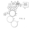
- Fig. 1 illustrates an offset press system using the method and apparatus for measuring the area of image portion according to the present invention.
- the system has an area data measuring device 12 for optically measuring basic data for obtaining the area or area factor of image portion of each of a plurality of ink control zones of a printing plate 11, a container device 13 for temporarily storing printing plates 11 the area data of which were measured, and a plurality of presses 14a, 14b, ... into which each printing plate is loaded for printing.
- the data measured in area data measuring device 12 are recorded on a magnetic card 15 and the magnetic card is attached to the corresponding printing plate 11.
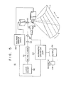
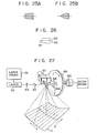
- Two-dimensional scanning of printing plate 11 by the laser beam is performed such that the X axis scanning is performed by first galvano mirror 53 with the laser beam position on the Y axis fixed and the Y axis scanning or the shifting of the position on the Y axis is performed by second galvano mirror 54.
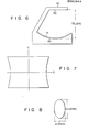
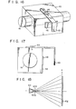
- printing plate 11 is placed on the upper surface of a fixing mount 60 provided at the lower part of measuring device, the upper surface being formed to describe circular arc along the Y axis direction of the printing plate as indicated in Fig. 6.
- an optical system setting section 61 is provided which irradiates the laser beam to printing plate 11.
- the first and second galvano mirrors the General Scanning Incorporated XY300 series are used, and as the galvano mirror control device the same company's AXY-150 two- channel drive amplifier is used.
- First galvano mirror 53 is driven to start the scanning along the X axis direction.
- the shading corrected data stored in RAM 78 and the reference reflected light data I B and I W for the image portion and the non-image portion are sent to output device 58 to be recorded on a magnetic tape. In this way, the measurement of area data is completed.
- the magnetic tape on which the measured data are recorded is then attached with an adhesive tape to a measured printing plate. The printing plate is then stored in the container.
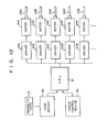
- CPU 91 reads out, from control device 92, the data of the width (P mm) of ink control zones of the printing press, the quality of the ink used, the printing speed, and the quality of printing paper.
- the quantity of ink supply for the corresponding control zone is selected from a data table stored in ROM so that the number Pi of drive pulses for the corresponding ink key drive motor is determined.
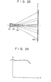
- the distribution of received light quantity as shown by the solid line in Fig. 15 can be obtained by calculation.
- the distribution of received light quantity can be changed.
- an optical filter 140 having a density distribution in which the transmittance gradually increases from the middle toward the periphery is used as the douser.
- a uniform distribution of received light may be provided.
Landscapes
- Physics & Mathematics (AREA)
- General Physics & Mathematics (AREA)
- Inking, Control Or Cleaning Of Printing Machines (AREA)
- Length Measuring Devices By Optical Means (AREA)
Applications Claiming Priority (2)
| Application Number | Priority Date | Filing Date | Title |
|---|---|---|---|
| JP56202421A JPS58105007A (ja) | 1981-12-17 | 1981-12-17 | 画像面積測定装置 |
| JP202421/81 | 1981-12-17 |
Publications (3)
| Publication Number | Publication Date |
|---|---|
| EP0082644A2 true EP0082644A2 (fr) | 1983-06-29 |
| EP0082644A3 EP0082644A3 (en) | 1984-05-30 |
| EP0082644B1 EP0082644B1 (fr) | 1987-09-16 |
Family
ID=16457220
Family Applications (1)
| Application Number | Title | Priority Date | Filing Date |
|---|---|---|---|
| EP82306587A Expired EP0082644B1 (fr) | 1981-12-17 | 1982-12-09 | Appareil pour la mesure de la surface de la portion-image d'un porteur d'images |
Country Status (4)
| Country | Link |
|---|---|
| US (1) | US4510866A (fr) |
| EP (1) | EP0082644B1 (fr) |
| JP (1) | JPS58105007A (fr) |
| DE (1) | DE3277325D1 (fr) |
Families Citing this family (12)
| Publication number | Priority date | Publication date | Assignee | Title |
|---|---|---|---|---|
| JPS58153109A (ja) * | 1982-03-08 | 1983-09-12 | Toppan Printing Co Ltd | 絵柄面積率測定装置 |
| DE3465930D1 (en) * | 1983-11-04 | 1987-10-15 | Gretag Ag | Method and device for controlling the ink supply in an offset printing machine, and offset printing machine provided with such a device |
| US5182721A (en) * | 1985-12-10 | 1993-01-26 | Heidelberger Druckmaschinen Aktiengesellschaft | Process and apparatus for controlling the inking process in a printing machine |
| US4926251A (en) * | 1987-04-07 | 1990-05-15 | Kabushiki Kaisha Toshiba | Color image processing apparatus with image corrector |
| US4967379A (en) * | 1987-12-16 | 1990-10-30 | Gretag Aktiengesellschaft | Process for the ink control or regulation of a printing machine by comparing desired color to obtainable color data |
| DE58901780D1 (de) * | 1988-01-14 | 1992-08-13 | Gretag Ag | Verfahren und vorrichtung zur farbregelung einer druckmaschine. |
| US8534194B2 (en) * | 2006-10-23 | 2013-09-17 | Bobst Bielefeld Gmbh | Rotary printing press and method for adjusting a cylinder thereof |
| EP2089227A2 (fr) * | 2006-10-23 | 2009-08-19 | Fischer & Krecke GmbH | Presse rotative et procédé pour ajuster un de ses cylindres |
| DE602006012688D1 (de) † | 2006-10-23 | 2010-04-15 | Fischer & Krecke Gmbh | Verfahren, Monatagevorrichtung und Steuereinheit zur Justierung einer Walze in einer Druckmaschine |
| CN102288115B (zh) * | 2011-07-11 | 2013-04-17 | 南京信息工程大学 | 滚子几何尺寸精密在线检测方法 |
| US8683922B2 (en) * | 2012-06-12 | 2014-04-01 | Goss International Americas, Inc. | Closed loop ink control system for a printing press |
| IT202000013093A1 (it) * | 2020-06-03 | 2021-12-03 | Andrea Belloli | Sistema per la gestione, il controllo e la verifica delle operazioni di stampa effettuate da una matrice di stampa. |
Family Cites Families (11)
| Publication number | Priority date | Publication date | Assignee | Title |
|---|---|---|---|---|
| DE869874C (de) * | 1951-04-20 | 1953-03-09 | Wilhelm Dipl-Chem Dr Stuermer | Photoelektrische Flaechenmessmaschine |
| US3185088A (en) * | 1961-12-01 | 1965-05-25 | Harris Intertype Corp | Method and apparatus for predetermining settings for ink fountain keys |
| US3448458A (en) * | 1967-06-16 | 1969-06-03 | Ncr Co | Laser recorder with scanning and display systems |
| US3646568A (en) * | 1969-04-03 | 1972-02-29 | Rca Corp | Beam control system |
| US3841215A (en) * | 1972-10-20 | 1974-10-15 | Ricoh Kk | Method and apparatus for control of the supply of ink for offset duplicating machines |
| JPS50154013A (fr) * | 1974-06-01 | 1975-12-11 | ||
| US3958509A (en) * | 1974-06-13 | 1976-05-25 | Harris Corporation | Image scan and ink control system |
| JPS5829489B2 (ja) * | 1974-07-23 | 1983-06-23 | 富士写真フイルム株式会社 | ヒカリソウサキノ ドウキコウサイシユホウホウ |
| JPS5566705A (en) * | 1978-11-13 | 1980-05-20 | Tatsuo Ehata | Planimeter |
| DE2926629A1 (de) * | 1979-07-02 | 1981-01-15 | Mohn Gmbh Reinhard | Verfahren und vorrichtung zur bestimmung von soll-werten fuer die insbesondere automatische voreinstellung von druckmaschinen |
| DE2950606A1 (de) * | 1979-12-15 | 1981-06-19 | M.A.N.- Roland Druckmaschinen AG, 6050 Offenbach | Vorrichtung zur zonenweisen optoelektronischen messung der flaechendeckung einer druckvorlage |
-
1981
- 1981-12-17 JP JP56202421A patent/JPS58105007A/ja active Granted
-
1982
- 1982-12-09 DE DE8282306587T patent/DE3277325D1/de not_active Expired
- 1982-12-09 EP EP82306587A patent/EP0082644B1/fr not_active Expired
- 1982-12-13 US US06/449,201 patent/US4510866A/en not_active Expired - Lifetime
Also Published As
| Publication number | Publication date |
|---|---|
| EP0082644A3 (en) | 1984-05-30 |
| US4510866A (en) | 1985-04-16 |
| JPS6322522B2 (fr) | 1988-05-12 |
| JPS58105007A (ja) | 1983-06-22 |
| DE3277325D1 (en) | 1987-10-22 |
| EP0082644B1 (fr) | 1987-09-16 |
Similar Documents
| Publication | Publication Date | Title |
|---|---|---|
| US4424589A (en) | Flat bed scanner system and method | |
| US4510866A (en) | Apparatus for measuring the area of image portion of image-bearing member | |
| EP1311108B1 (fr) | Procédé de correction de l'intensité d'un faisceau dans un dispositif d'enregistrement d'images utilisant un modulateur de lumière multicanal | |
| GB2134351A (en) | Method for correcting beam intensity upon scanning and recording a picture | |
| US4524388A (en) | Shading correction device | |
| EP0590559B1 (fr) | Dispositif de lecture d'images | |
| JPH0691935A (ja) | 光学イメージングシステムの等化方法 | |
| US6603499B2 (en) | Printhead having non-uniformity correction based on spatial energy profile data, a method for non-uniformity correction of a printhead, and an apparatus for measuring spatial energy profile data in a printhead | |
| US4928277A (en) | Method and apparatus for driving laser beam source to avoid droop effects | |
| JP3769895B2 (ja) | 画像形成装置 | |
| GB2312114A (en) | Controlling pixel rate in a scanned image recording device | |
| US4902084A (en) | Optical scanning system | |
| US6423964B2 (en) | Method and apparatus for adjusting amount of light in image exposure recording system | |
| US4937620A (en) | Method of focusing printer | |
| EP0919883B1 (fr) | Module de balayage à laser et procédé pour le synchroniser | |
| WO1992002368A1 (fr) | Gravure d'un element d'impression | |
| US20030189633A1 (en) | System and method for calibrating a laser line illumination system for use in imaging systems | |
| US5663554A (en) | Weak lens focus adjusting mechanism based upon thickness of scanned material and imagesetter using same | |
| JPH04179370A (ja) | 画像記録装置における濃度補正装置 | |
| EP0677383A2 (fr) | Appareil de composition d'images pour abouter des bandes imprimées | |
| US5302972A (en) | Method of setting density for image recording apparatus | |
| EP1094950B1 (fr) | Commande de l'intensite des pixels dans des modulateurs electro-optiques | |
| EP0571149A2 (fr) | Appareil de composition d'images | |
| US6842188B2 (en) | Method for setting focus of a multichannel printhead | |
| JP2659028B2 (ja) | 露光装置 |
Legal Events
| Date | Code | Title | Description |
|---|---|---|---|
| PUAI | Public reference made under article 153(3) epc to a published international application that has entered the european phase |
Free format text: ORIGINAL CODE: 0009012 |
|
| 17P | Request for examination filed |
Effective date: 19821217 |
|
| AK | Designated contracting states |
Designated state(s): CH DE FR GB LI |
|
| PUAL | Search report despatched |
Free format text: ORIGINAL CODE: 0009013 |
|
| AK | Designated contracting states |
Designated state(s): CH DE FR GB LI |
|
| RAP1 | Party data changed (applicant data changed or rights of an application transferred) |
Owner name: TOSHIBA MACHINE COMPANY LIMITED Owner name: KABUSHIKI KAISHA TOSHIBA |
|
| 17Q | First examination report despatched |
Effective date: 19860129 |
|
| R17C | First examination report despatched (corrected) |
Effective date: 19860812 |
|
| GRAA | (expected) grant |
Free format text: ORIGINAL CODE: 0009210 |
|
| AK | Designated contracting states |
Kind code of ref document: B1 Designated state(s): DE GB |
|
| REF | Corresponds to: |
Ref document number: 3277325 Country of ref document: DE Date of ref document: 19871022 |
|
| PLBE | No opposition filed within time limit |
Free format text: ORIGINAL CODE: 0009261 |
|
| STAA | Information on the status of an ep patent application or granted ep patent |
Free format text: STATUS: NO OPPOSITION FILED WITHIN TIME LIMIT |
|
| 26N | No opposition filed | ||
| PGFP | Annual fee paid to national office [announced via postgrant information from national office to epo] |
Ref country code: GB Payment date: 19961202 Year of fee payment: 15 |
|
| PGFP | Annual fee paid to national office [announced via postgrant information from national office to epo] |
Ref country code: DE Payment date: 19970226 Year of fee payment: 15 |
|
| PG25 | Lapsed in a contracting state [announced via postgrant information from national office to epo] |
Ref country code: GB Free format text: LAPSE BECAUSE OF NON-PAYMENT OF DUE FEES Effective date: 19971209 |
|
| GBPC | Gb: european patent ceased through non-payment of renewal fee |
Effective date: 19971209 |
|
| PG25 | Lapsed in a contracting state [announced via postgrant information from national office to epo] |
Ref country code: DE Free format text: LAPSE BECAUSE OF NON-PAYMENT OF DUE FEES Effective date: 19980901 |