EP0082645A1 - Lagemesssysteme mit Servospur - Google Patents
Lagemesssysteme mit Servospur Download PDFInfo
- Publication number
- EP0082645A1 EP0082645A1 EP82306595A EP82306595A EP0082645A1 EP 0082645 A1 EP0082645 A1 EP 0082645A1 EP 82306595 A EP82306595 A EP 82306595A EP 82306595 A EP82306595 A EP 82306595A EP 0082645 A1 EP0082645 A1 EP 0082645A1
- Authority
- EP
- European Patent Office
- Prior art keywords
- transducer
- response
- output
- residual
- receive
- Prior art date
- Legal status (The legal status is an assumption and is not a legal conclusion. Google has not performed a legal analysis and makes no representation as to the accuracy of the status listed.)
- Granted
Links
- 238000001514 detection method Methods 0.000 title abstract description 3
- 238000006073 displacement reaction Methods 0.000 claims abstract description 14
- 230000007704 transition Effects 0.000 claims abstract description 5
- 238000005259 measurement Methods 0.000 claims abstract description 3
- 230000004044 response Effects 0.000 claims description 71
- 230000001939 inductive effect Effects 0.000 claims description 6
- 230000002452 interceptive effect Effects 0.000 claims description 5
- 230000003111 delayed effect Effects 0.000 claims description 4
- 230000003993 interaction Effects 0.000 claims description 3
- 238000011084 recovery Methods 0.000 claims description 2
- 230000006698 induction Effects 0.000 claims 5
- 239000002131 composite material Substances 0.000 description 8
- 238000000034 method Methods 0.000 description 8
- 230000009977 dual effect Effects 0.000 description 7
- 230000008859 change Effects 0.000 description 5
- 238000013500 data storage Methods 0.000 description 4
- 230000004907 flux Effects 0.000 description 3
- 230000003287 optical effect Effects 0.000 description 3
- 230000001419 dependent effect Effects 0.000 description 2
- 238000009499 grossing Methods 0.000 description 2
- 230000008569 process Effects 0.000 description 2
- 230000001960 triggered effect Effects 0.000 description 2
- 239000003990 capacitor Substances 0.000 description 1
- 238000010276 construction Methods 0.000 description 1
- 230000001934 delay Effects 0.000 description 1
- 230000002939 deleterious effect Effects 0.000 description 1
- 230000000694 effects Effects 0.000 description 1
- 238000013213 extrapolation Methods 0.000 description 1
- 230000007246 mechanism Effects 0.000 description 1
- 238000005070 sampling Methods 0.000 description 1
- 230000003068 static effect Effects 0.000 description 1
Images


Classifications
-
- G—PHYSICS
- G11—INFORMATION STORAGE
- G11B—INFORMATION STORAGE BASED ON RELATIVE MOVEMENT BETWEEN RECORD CARRIER AND TRANSDUCER
- G11B21/00—Head arrangements not specific to the method of recording or reproducing
- G11B21/02—Driving or moving of heads
- G11B21/10—Track finding or aligning by moving the head ; Provisions for maintaining alignment of the head relative to the track during transducing operation, i.e. track following
- G11B21/106—Track finding or aligning by moving the head ; Provisions for maintaining alignment of the head relative to the track during transducing operation, i.e. track following on disks
-
- G—PHYSICS
- G11—INFORMATION STORAGE
- G11B—INFORMATION STORAGE BASED ON RELATIVE MOVEMENT BETWEEN RECORD CARRIER AND TRANSDUCER
- G11B5/00—Recording by magnetisation or demagnetisation of a record carrier; Reproducing by magnetic means; Record carriers therefor
- G11B5/48—Disposition or mounting of heads or head supports relative to record carriers ; arrangements of heads, e.g. for scanning the record carrier to increase the relative speed
- G11B5/58—Disposition or mounting of heads or head supports relative to record carriers ; arrangements of heads, e.g. for scanning the record carrier to increase the relative speed with provision for moving the head for the purpose of maintaining alignment of the head relative to the record carrier during transducing operation, e.g. to compensate for surface irregularities of the latter or for track following
- G11B5/596—Disposition or mounting of heads or head supports relative to record carriers ; arrangements of heads, e.g. for scanning the record carrier to increase the relative speed with provision for moving the head for the purpose of maintaining alignment of the head relative to the record carrier during transducing operation, e.g. to compensate for surface irregularities of the latter or for track following for track following on disks
- G11B5/59688—Servo signal format patterns or signal processing thereof, e.g. dual, tri, quad, burst signal patterns
Definitions
- the present invention relates to systems for detecting the positions of benchmarks on a recording medium. It particularly relates to systems where the direction and magnitude of the displacement of a transducer from being centrally disposed over a servo track recorded on a moving medium is indicated by the output of a decoder in receipt of signals recovered from the servo track by the transducer. Most particularly it relates to such systems where the medium is magnetic tape or disc for the recording of informational data signals.
- the output of the decoder can then be variously used to give indication of the position of the servo track relatively to an external position measuring system to a controller for the controller to use that information to locate the transducer over other, data storage tracks by interpolation or extrapolation, or directly as a position feedback signal in a transducer-positioning servo mechanism to centre the transducer over the servo track.
- the present invention consists in a system for indicating the position of a transducer relatively to a servo track on a moving medium, said servo track comprising first and second sub-tracks, said first sub-track comprising a first component operable to induce a first response in said transducer and a second component operable to induce a second response in said transducer, and said second sub-track comprising a third component operable to induce a third response in said transducer and a fourth component operable to induce a fourth response in said transducer, said first and second sub-tracks being simultaneously accessible by said transducer, said second and fourth components being simultaneously detectable by said transducer, and said second and fourth responses having a polarity opposite to one another and respective magnitudes dependent upon the respective extents of transducer interaction with said first and second sub-tracks, said system comprising a decoder coupled to receive signals recovered from said medium by said transducer and operable to detect and respond to the receipt of said first and third responses to
- the present invention consists in a system according to the first aspect characterised by said first and third components being simultaneously detectable by said transducer and by said decoder being operable to take said sample by multiplying s.aid residual response resulting from the cancellation in whole or in part of said second and fourth responses by the rectified and delayed residual response resulting from the cancellation in whole or in part of said first and third responses.
- a servo track is recorded on a moving medium.
- the medium is preferably magnetic.
- the magnetic medium is preferably a disc for digital, informational data recording.
- the servo track preferably comprises a first sub-track and a second sub-track.
- the first and second sub-tracks are preferably recorded contiguously along a median line.
- the sub-tracks are preferably equal in width or wider than a transducer for recovering signals from the medium.
- the first and second sub-tracks each preferably comprise areas of a first polarity of magnetisation and areas of a second polarity of magnetisation.
- the boundaries between the areas of first and second polarities of magnetisation are preferably rectilinear and at right angles to the median line in each sub-track.
- the first sub-track preferably comprises a first boundary being a transition from the first polarity of polarisation of magnetisation to the second, and thereafter a second boundary being a transition of magnetic polarisation from the second to the first polarity.
- the second sub-track preferably comprises a third boundary being atransition from magnetisation of the second polarity to magnetisation of the first polarity, and a fourth boundary being a transition from the magnetic polarisation of the first polarity to . polarisation of the second polarity.
- the second boundary in the first sub-track is preferably aligned with the fourth boundary of the second sub-track.
- the first boundary of the first sub-track is preferably aligned with the third boundary of the second sub-track.
- the transducer preferably responds to the difference in the change of magnetic flux encountered as the alignment of the third and first boundaries passes therebeneath to provide a first residual pulse whose amplitude is proportional to the relative difference between the amounts of said first and second sub-tracks interacting with the transducer.
- the transducer preferably responds to the change in magnetic flux encountered as the alignment of the fourth and second boundaries passes therebeneath to provide a second residual pulse whose amplitude and sense is proportional to the relative difference between the amounts of said first and second sub-tracks interacting with the transducer.
- a composite peak detector is operable to detect the first residual pulse and is response thereto to operate a timer.
- the timer preferably opens an analog gate during the period of receipt of the second residual pulse.
- the output of the analog gate is preferably provided as the input to a smoothing circuit.
- the smoothing circuit is preferably a low pass filter.
- the input to the analog gate is preferably the signal recovered by the transducer from the servo track.
- the output of the low pass filter is preferably provided as the output of the decoder.
- the timer is preferably non-retriggerable during its time operation and has a period less than the time between successive first residual pulses.
- the composite peak detector preferably comprises a positive peak detector, a negative peak detector, and an "OR" gate for combining the logical pulse outputs of the two.
- the signal recovered from the servo track by the transducer is coupled as the rectified input to a multiplier.
- the signal from the transducer is preferably supplied as the input to a delay circuit.
- the delay circuit preferably delays the transducer output signal by a time equal to the interval between a first residual pulse and a second residual pulse.
- the output of the delay circuit is preferably provided as the second input to the multiplier.
- the output of the multiplier is preferably the analog multiple of its two inputs and is coupled via a low pass filter as the output of the decoder.
- a second preferred embodiment of the servo track all is as in the first preferred embodiment of the servo track save that the first and third boundaries in the first and second sub-tracks respectively are not aligned so that the first residual pulse is lost and becomes first and second timing pulses whose amplitudes are substantially independent of the position of the transducer relative to the median line.
- the distance from the first to the second boundaries is less than the distance between the second boundary and any subsequent first boundary and the distance between the third boundary and the fourth boundary is less than the distance between the fourth boundary and any subsequent third boundary.
- a third preferred embodiment of the decoder for use with the second preferred embodiment of the servo track, all is as in the first preferred embodiment of the decoder save that the composite peak detector is replaced with a dual peak detector for detecting the first and/or second timing pulses.
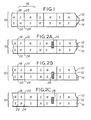
- Figure 1 shows the servo track in its first preferred embodiment.
- the servo track 10 comprises a first sub-track 12 and a second sub-track 14 contiguously recorded along a'median line 15.
- Both sub-tracks 12 14 comprises areas of a first polarity of magnetisation N alternating with areas of a second polarity of magnetisation S, the servo track 10 being recorded on a magnetic informational data storage rotary disc.
- the boundaries between the first areas N and the second areas S are everywhere at right angles to median line 15.
- the areas N S alternate along the length of the servo track 10 to form a repetitious plurality of servo patterns 16.
- the pattern 16 comprises a first boundary 18 between a first area N and a second area S and a second boundary 20 between a second area S and a first area N.
- the pattern 16 comprises a third boundary 22 between a second area S and a first area N and a fourth boundary 24 between a first area N and a second area S.
- the first boundary 18 is co-incident with the third boundary 22 along the length of the track 10 with a magnetisation change-of opposite sense and the second boundary 20 is similarly co-incident and similarly opposite in sense with the fourth boundary.
- the distance between the first boundary 18 and the second boundary 20 is less than the distance between the second boundary 20 and the subsequent first boundary 18 in a pattern. Because of the coincidence of the first and third boundaries 18 22 and of the second and fourth boundaries 20 24 the same relationship holds in linear spacing for the third to the fourth boundaries 22 24 as holds for the first to the second boundaries 18 20 respectively.
- the servo track 10 is here depicted as comprising a repetetive plurality of patterns the description equally applies where the servo track 10 comprises just a single pattern 16 as might be encountered when servo information is laid down among other signals on a common track.
- Figure 2A shows a magnetic head 26 disposed over the servo track 10 such that it is more interactive with the first sub-track 12 than with the second 14.
- the boundaries 18 20 22 24 each cause an output pulse in the head 26 whose amplitude is proportional to the relative extend of the width of the head 26 over which the boundary 18 20 22 24 extends and whose polarity is dependent upon the sense of the change of polarisation of magnetisation N S of the boundary 18 20 22 24.
- the first and second boundaries 18 20 will produce greater output than the third and fourth boundaries 22 24.
- Figure 2B shows the head 26 disposed more over the second sub-track 14 than over the first sub-track 12.
- the third and fourth boundaries 22 24 produce greater output from the head 26 than do the first and second boundaries 18 20.
- Figure 2C shows the head 26 equally disposed over both sub-tracks 12 14 so that the first and second boundaries 18 20 produce the same output amplitudes as do the third and fourth boundaries 22 24.
- the head 26 is representative of the area of interaction of any kind of transducer on any recording medium.
- the head is magnetic and the representation 26 thereof indicates the flux- intercepting gap of such a head.
- the representation 26 can be taken as indicating a laser reader for optical discs and the like.
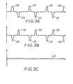
- Figure 3A shows the output waveform recovered from the track 10 by the head 26 when in the position indicated in figure 2A.
- the head 26 is static and the track 10 moves toweards the left of figures 2A to 2C with uniform velocity.
- This can be achieved when the track 10 is on moving tape by movement of the tape in the conventional manner.
- the track 10 is recorded on a disc the movement of the track 10 is achieved by rotation of the disc, in which circumstance the track 10 as depicted in figures 2A to 2C is in fact a portion of a circular track 10 extending right round the disc at a predetermined radius relative to the centre of rotation.
- the first and third boundaries 18 22 pass beneath the head 26 simultaneously.
- the first boundary 18 being from the first sense of magnetisation N to the second S induces a positive pulse response in the head 26 and the third boundary being from the second sense of magnetisation S to the first N induces a negative pulse response in the head 26.
- the head 26 is more over the first boundary 18 than over the third boundary 22, the amplitude of the response from the first boundary 18 therefore being greater than the amplitude of the response from the third boundary 22.
- the responses from the first and third boundaries 18 22 partially cancel to leave a first residual pulse 28 which is predominantly positive.
- the second and fourth boundaries 20 24 pass beneath the head 26 simultaneously the second boundary 20 inducing a negative pulse response in the head 26 and the fourth boundary 24 inducing a positive pulse response in the head 26.
- the response from the second boundary 20 has a greater size than the response from the fourth boundary 24 because of the position of the head 26.
- the two responses cancel in part to leave a second residual pulse 30 of the same size but opposite polarity to the first residual pulse 28.
- Figure 3B shows the output waveform of the head 26 when in the position depicted in figure 2B.
- the head 26 is more over the second sub-track 14 than over the first 12 so that the amplitude of the response induced in the head 26 by the third boundary 22 is greater than the amplitude of the response induced in the head by the first boundary 18 and the amplitude of the response induced in the head 26 by the fourth boundary 24 is greater than the amplitude of the response induced in the head 26 by the second boundary 20.
- the first residual pulse 28 is therefore negative and the second residual pulse 30 is positive and of the same size.
- Figure 3C shows the output waveform of the head 26 when in the position depicted in figure 2C.
- the head 26 is equally over both sub-tracks 12 14 and the first boundary 18 induces an equal and opposite response to the negative response induced in the head 26 by the third boundary 22.
- the second boundary 20 induces a negative pulse response in the head 26 which is equal and opposite to the positive pulse response induced in the head 26 by the fourth boundary.
- the responses each being equal and opposite to their respective opposed response, the output of the head 26 reduces to the zero line 32, the amplitude of the first and second residual pulses 28 30 having been reduced to nothing by cancellation.
- first residual pulse 28 reaches maximum positive value and the second residual pulse 30 reaches maximum negative value when the head 26 is entirely over the first sub-track 12.
- first residual pulse 28 reaches maximum negative value and the second residual pulse 30 reaches maximum positive value when the head 26 is entirely over the second sub-track 14.
- the amplitudes of the first and second residual pulses 28 30 increase together linearly with the magnitude of displacement of the head 26 from being central over the medial line 15 and have a polarity which depends upon the direction from the median line 15 in which the head 26 is displaced.
- Figure 4 shows a first preferred embodiment of the decoder for use with the servo track 10 of figure 1.
- the composite peak detector 36 responds to the first residual pulse 28 to provide a trigger pulse on a trigger line 38.
- the composite peak detector 36 can be of any kind known in the art for detecting such pulses, for example comprising a positive peak detector and a negative peak detector each in receipt of the input line 34 and operable in response to the provision thereon of a positive first residual pulse 28 or a negative first residual pulse 28 respectively to provide a logic output, the logic outputs of the first and second peak detectors being provided as the inputs to an "OR" gate, or being "Wire 0r'ed” together to provide logically one output or the other as the signal on the trigger line 28.
- the positive and negative peak detectors are required to respond to pulses of very small amplitude such as are encountered when the head 26 is close to central disposition over the servo track 10.
- the point at which pulses 28 cease to be detected by the detector 36 can be chosen by appropriate selection of the type of peak detectors employed and by manipulation of their parameters to lie as close to central disposition of the head 26 over the track 10 as is desired.
- the signal on the trigger line 38 is used as the triggering input for a timer 4C.
- the timer On receipt of the triggering pulse from the detector 36, the timer starts an operation which consists in waiting for a first predetermined time until just before the arrival of the second residual pulse 30, then supplying a window signal on a window line 42 until a little after the arrival of the second residual pulse 30.
- the timing may variously be performed with counters, monostable timers and the like and it will be readily apparent to those skilled in the art how such a timer can be constructed.
- the timer 40 once started, is not retriggerable by subsequent pulses on the trigger line 38. Thus, should the detector 36 provide an output in response to the second residual pulse 30 the additional response of the detector 36 does not affect the operation of the timer.
- feed-back can be provided from the timer 40 to the detector 36 to inhibit its operation during the operation of the timer.
- the duration of the operation of the timer 40 is such that it is completed before the arrival of any subsequent first residual pulse 28 subsequently to having been triggered (erroneously) by a second residual pulse 30. In this way it is impossible for the timer 40 to become locked onto the wrong residual pulse 30 stream. At very worst the timer will mis-operate for only one pattern 16. It will be apparent how the spacing between the first and second residual pulses 28 30 and between the second and first residual pulses 30 28 should be arranged to accomplish this end.
- the window signal on the window line 42 is provided as the controlling input to an analog gate 44.
- the signal from the servo track 10 picked up by the head 26 is supplied via the input line 34 as the analog input to the gate 44.
- the gate 44 opens to provide as output the analog signal provided on its analog input. Since the window signal is provided by the timer 40 only when the second residual pulse 30 arrives, the output of the gate 44 consists entirely in a serial stream of successive second residual pulses 30.
- the mean level of the second residual pulses 30 is indicative by magnitude of the size of the displacement of the head 26 from central disposition over the track 10 and indicative by polarity of the direction of that displacement.
- the output of the analog gate 44 is provided as the input to a low pass filter 46 whose output, provided on the decoder output line 48, is the mean of its input.
- the decoder as described thus has only one pulse height measuring channel with very few components so avoiding the errors induced by component tolerances in those decoders where first and second measuring channels measure pulse height and provide representative signals to a comparator.
- the comparison of pulse heights occurs by flux summing in the head 26.
- Figure 5 shows a second preferred embodiment of the decoder for use with the servo track 10 of figure 1.
- the amplified and filtered signal recovered by the head 26 from the track 10 is supplied via a signal line 50 as the input to a rectifier 53.
- the rectifier 53 always provides a positive representation of its input signal regardlessly of its actual input signal polarity.
- the rectifier 52 can be any one of a number of circuits and those shilled in the art will be aware of methods for the implementation thereof using transistor circuits, bridge rectifiers, amplifier feedback circuits and the like.
- the output of the rectifier 52 is provided on a rectifier output line 53 as the first input to an analog multiplier 56.
- the signal input line 50 also provides the input to a delay 54 whose output is a delayed representation of input having the same polarity as its input and retarded by an amount of time equal to the period between the first residual pulse 28 and the second residual pulse 30.
- the delay 54 is any type of analog delay ranging from a conventional inductor- capacitor delay line to a charge coupled bucket brigade device, dependently upon the speed required.
- the output of the delay 54 is coupled via a delay output line 55 as the second input to the analog multiplier 56.
- the multiplier 56 responds to its first and second inputs to provide an output signal which is representative of the product of the instantaneous value of the signal on the rectifier output line 53 and of the instantaneous value of the signal on the delay output line 55.
- the period between the first residual pulse 28 and the second residual pulse 30 is less than the period between the second residual pulse 30 and the subsequent first residual pulse 28.
- the rectified second residual pulse 30 is arriving as the first input to the multiplier 56 the delayed first residual pulse 28 is arriving on the second input to the multiplier 56 and the multiplier 56 provides an output representative of the product therebetween.
- the second residual pulse 30 is arriving via the delay 54 as the second input to the multiplier 56 the first input to the multiplier 56 via the rectifier 52 is providing no signal and the output of the multiplier 56 is accordingly zero.
- the multiplier 56 therefore provides a succession of output pulses on a multiplier output line 58 being the first residual pulse 28 multiplied by the sampling function of the rectified second residual pulse 30.
- the output pulses of the rectifier are therefore representative of the sense of the first residual pulse 28 and of the magnitude of the product of the magnitudes of the first and second residual pulses 28 30.
- the output pulses from the multiplier 56 are smoothed and averaged by a low-pass filter 60 as before.
- Figure 6 shows a second preferred embodiment of the servo track.
- the second preferred track 64 comprises first and second sub-tracks 66 68 contiguous along a median line 67 and corresponding to the first and second sub-tracks 12 14 and median line 15 of figure 1.
- a servo pattern 69 is optionally repeated along the length of the track 64 just as the pattern 16 in the first preferred track 10 is optionally repeated.
- First, second third and fourth boundaries 70 72 74 76 correspond to the first second third and fourth boundaries 18 20 22 24 of the first preferred embodiment of the track 10.
- the only difference between the second preferred'track 64 and the first preferred track is that in the second preferred track 64 the first boundary 70 is not aligned with the third boundary 74 so that the pulse responses they induce in the head 26 are no longer co-incident in and do not cancel.
- Figure 7 shows the signal recovered by the head 26 from the second preferred track 64.
- the first boundary 70 induces a first, positive timing pulse 78 in the head 26.
- the third boundary 74 induces a second, negative timing pulse 80 in the head 26.
- the opposition of the second boundary 72 and the fourth boundary 76 as they pass beneath the head 26 cause a position indicating residual pulse 80 whose sense is indicative of the direction of the displacement of the head 26 from central disposition over the track 64 and whose amplitude is indicative of the size of that displacement.
- the signal is here shown as if the head 26 is disposed more over the first sub-track 66 than over the second sub-track 68.
- the first timing pulse 78 is always positive and the second timing pulse 80 is always negative.
- the first timing pulse 78 is at a maximum value and the second timing pulse 80 is at zero value.
- the first timing pulse 78 has zero amplitude and the second timing pulse 80 has maximum amplitude.
- the first and second timing pulses 78 80 have intermediate values and their amplitudes always add up to the maximum value, their particular values being determined by the proportional part o'f the width of the head 26 over each sub-track 66 68.
- Figure 8 shows a decoder suitable for use with second preferred embodiment of the servo track 64.
- the dual peak detector detects the passage of the first and second timing pulses 78 80.
- it can consist of two peak detectors and an "OR" gate just like the composite peak detector 36, with the difference that in the dual peak detector 84 there is no need to detect small amplitude pulses since one or other of the first and second timing pulses 78 80 will always be of large amplitude.
- the first predetermined period of the timer 40 should then be chosen such that it is immaterial to the operation of the window whether the first or second timing pulses 78 80 triggers the timer 40.
- the dual peak detector 84 can consist in a zero crossing detector which provides an output pulse if and only if its input voltage passes from positive to negative with more than a predetermined negative slope thereon.
- the sum of the amplitudes of the first and second timing pulses 78 80 can be exploited as a method for controlling the scaling factor of the amplitude of the residual pulse 82 by detecting and adding the sums of their 78 80 amplitudes and subtracting that sum from a predetermined level for use as the gain controlling signal in a gain controlled amplifier.
Landscapes
- Engineering & Computer Science (AREA)
- Signal Processing (AREA)
- Moving Of The Head To Find And Align With The Track (AREA)
Applications Claiming Priority (2)
| Application Number | Priority Date | Filing Date | Title |
|---|---|---|---|
| GB8138635 | 1981-12-22 | ||
| GB8138635 | 1981-12-22 |
Publications (2)
| Publication Number | Publication Date |
|---|---|
| EP0082645A1 true EP0082645A1 (de) | 1983-06-29 |
| EP0082645B1 EP0082645B1 (de) | 1986-01-22 |
Family
ID=10526783
Family Applications (1)
| Application Number | Title | Priority Date | Filing Date |
|---|---|---|---|
| EP19820306595 Expired EP0082645B1 (de) | 1981-12-22 | 1982-12-10 | Lagemesssysteme mit Servospur |
Country Status (3)
| Country | Link |
|---|---|
| EP (1) | EP0082645B1 (de) |
| DE (1) | DE3268718D1 (de) |
| GB (1) | GB2112183B (de) |
Cited By (3)
| Publication number | Priority date | Publication date | Assignee | Title |
|---|---|---|---|---|
| DE3335560A1 (de) * | 1982-10-01 | 1984-05-30 | Matsushita Electric Industrial Co., Ltd., Kadoma, Osaka | Scheibe zur messung des betrages der aussenspurlage eines magnetkopfes und die scheibe verwendendes messgeraet |
| EP0435255A1 (de) * | 1989-12-27 | 1991-07-03 | Nec Corporation | Magnetplattengerät |
| EP0849735A1 (de) * | 1996-12-20 | 1998-06-24 | Deutsche Thomson-Brandt Gmbh | Kombinierte longitudinale und transversale Spurnachführung |
Citations (4)
| Publication number | Priority date | Publication date | Assignee | Title |
|---|---|---|---|---|
| US3534344A (en) * | 1967-12-21 | 1970-10-13 | Ibm | Method and apparatus for recording and detecting information |
| US3593333A (en) * | 1969-11-26 | 1971-07-13 | Ibm | Position detection for a track following servo system |
| FR2126698A5 (de) * | 1971-02-08 | 1972-10-06 | Ibm | |
| GB2054214A (en) * | 1979-07-19 | 1981-02-11 | Burroughs Corp | Transducer positioning system |
-
1982
- 1982-12-08 GB GB08234960A patent/GB2112183B/en not_active Expired
- 1982-12-10 EP EP19820306595 patent/EP0082645B1/de not_active Expired
- 1982-12-10 DE DE8282306595T patent/DE3268718D1/de not_active Expired
Patent Citations (4)
| Publication number | Priority date | Publication date | Assignee | Title |
|---|---|---|---|---|
| US3534344A (en) * | 1967-12-21 | 1970-10-13 | Ibm | Method and apparatus for recording and detecting information |
| US3593333A (en) * | 1969-11-26 | 1971-07-13 | Ibm | Position detection for a track following servo system |
| FR2126698A5 (de) * | 1971-02-08 | 1972-10-06 | Ibm | |
| GB2054214A (en) * | 1979-07-19 | 1981-02-11 | Burroughs Corp | Transducer positioning system |
Non-Patent Citations (1)
| Title |
|---|
| IBM TECHNICAL DISCLOSURE BULLETIN, vol. 18, no. 8, January 1976, pages 2656-2657, New York (USA); * |
Cited By (5)
| Publication number | Priority date | Publication date | Assignee | Title |
|---|---|---|---|---|
| DE3335560A1 (de) * | 1982-10-01 | 1984-05-30 | Matsushita Electric Industrial Co., Ltd., Kadoma, Osaka | Scheibe zur messung des betrages der aussenspurlage eines magnetkopfes und die scheibe verwendendes messgeraet |
| EP0435255A1 (de) * | 1989-12-27 | 1991-07-03 | Nec Corporation | Magnetplattengerät |
| EP0849735A1 (de) * | 1996-12-20 | 1998-06-24 | Deutsche Thomson-Brandt Gmbh | Kombinierte longitudinale und transversale Spurnachführung |
| US6122134A (en) * | 1996-12-20 | 2000-09-19 | Deutsche Thomson-Brandt Gmbh | Combined longitudinal and transversal tracking |
| KR100544800B1 (ko) * | 1996-12-20 | 2006-04-20 | 도이체 톰슨 브란트 | 결합된 종방향 및 횡방향 트래킹 |
Also Published As
| Publication number | Publication date |
|---|---|
| EP0082645B1 (de) | 1986-01-22 |
| GB2112183B (en) | 1985-05-09 |
| GB2112183A (en) | 1983-07-13 |
| DE3268718D1 (en) | 1986-03-06 |
Similar Documents
| Publication | Publication Date | Title |
|---|---|---|
| US4149198A (en) | Transducer positioning system | |
| US4101942A (en) | Track following servo system and track following code | |
| CA1079846A (en) | Record track following and seeking | |
| US4454549A (en) | Slant track sector servo | |
| US6384994B1 (en) | Method for positioning a magnetoresistive head using a thermal response to servo information on the record medium | |
| EP0094314B2 (de) | Positioniersteuerungssystem mit sowohl kontinuierlichen als auch eingefügten Servoinformationen für einen Magnetplattenspeicher | |
| US5867341A (en) | Disc drive system using multiple pairs of embedded servo bursts | |
| US4068269A (en) | Positioning system for data storage apparatus and record medium for use therewith | |
| JPH0136190B2 (de) | ||
| US8045282B2 (en) | Measurement of track eccentricity on bit patterned media | |
| JPS6120945B2 (de) | ||
| JPH0136188B2 (de) | ||
| US4516178A (en) | Cylinder crossing detection circuit for disc drive or the like | |
| US5608583A (en) | System for qualifying the detection of a servo dibit | |
| CA1265615A (en) | Digitally responsive system for positioning a transducer of a storage apparatus | |
| US4519007A (en) | Servo-track position detection systems | |
| EP0082645A1 (de) | Lagemesssysteme mit Servospur | |
| US5247398A (en) | Automatic correction of position demodulator offsets | |
| US4554600A (en) | Track following code and track following system | |
| US4405956A (en) | Tracking apparatus for read/write head | |
| US20040003193A1 (en) | Method and apparatus for enhanced phase alignment for direct access storage device (DASD) | |
| US5973869A (en) | Servo frame edge detection for tape servo pattern with synchronization field | |
| US5115360A (en) | Embedded burst demodulation and tracking error generation | |
| JPS59212712A (ja) | サ−ボ・トラック位置検出システム | |
| JPS6373180A (ja) | 磁気デイスクの突起検出方法 |
Legal Events
| Date | Code | Title | Description |
|---|---|---|---|
| PUAI | Public reference made under article 153(3) epc to a published international application that has entered the european phase |
Free format text: ORIGINAL CODE: 0009012 |
|
| 17P | Request for examination filed |
Effective date: 19821218 |
|
| AK | Designated contracting states |
Designated state(s): BE DE FR IT NL |
|
| GRAA | (expected) grant |
Free format text: ORIGINAL CODE: 0009210 |
|
| AK | Designated contracting states |
Designated state(s): BE DE FR IT NL |
|
| ET | Fr: translation filed | ||
| REF | Corresponds to: |
Ref document number: 3268718 Country of ref document: DE Date of ref document: 19860306 |
|
| ITF | It: translation for a ep patent filed | ||
| PLBE | No opposition filed within time limit |
Free format text: ORIGINAL CODE: 0009261 |
|
| STAA | Information on the status of an ep patent application or granted ep patent |
Free format text: STATUS: NO OPPOSITION FILED WITHIN TIME LIMIT |
|
| RAP2 | Party data changed (patent owner data changed or rights of a patent transferred) |
Owner name: BURROUGHS CORPORATION (A DELAWARE CORPORATION) |
|
| BECN | Be: change of holder's name |
Effective date: 19860122 |
|
| 26N | No opposition filed | ||
| NLT2 | Nl: modifications (of names), taken from the european patent patent bulletin |
Owner name: BURROUGHS CORPORATION TE DETROIT, MICHIGAN, VER. S |
|
| PGFP | Annual fee paid to national office [announced via postgrant information from national office to epo] |
Ref country code: BE Payment date: 19920114 Year of fee payment: 10 |
|
| ITTA | It: last paid annual fee | ||
| PG25 | Lapsed in a contracting state [announced via postgrant information from national office to epo] |
Ref country code: BE Effective date: 19921231 |
|
| BERE | Be: lapsed |
Owner name: BURROUGHS CORP. Effective date: 19921231 |
|
| PGFP | Annual fee paid to national office [announced via postgrant information from national office to epo] |
Ref country code: FR Payment date: 19941209 Year of fee payment: 13 |
|
| PGFP | Annual fee paid to national office [announced via postgrant information from national office to epo] |
Ref country code: DE Payment date: 19941223 Year of fee payment: 13 |
|
| PGFP | Annual fee paid to national office [announced via postgrant information from national office to epo] |
Ref country code: NL Payment date: 19941231 Year of fee payment: 13 |
|
| PG25 | Lapsed in a contracting state [announced via postgrant information from national office to epo] |
Ref country code: NL Effective date: 19960701 |
|
| PG25 | Lapsed in a contracting state [announced via postgrant information from national office to epo] |
Ref country code: FR Effective date: 19960830 |
|
| NLV4 | Nl: lapsed or anulled due to non-payment of the annual fee |
Effective date: 19960701 |
|
| PG25 | Lapsed in a contracting state [announced via postgrant information from national office to epo] |
Ref country code: DE Effective date: 19960903 |
|
| REG | Reference to a national code |
Ref country code: FR Ref legal event code: ST |