EP0082708A2 - Bogenzuführvorrichtung - Google Patents
Bogenzuführvorrichtung Download PDFInfo
- Publication number
- EP0082708A2 EP0082708A2 EP82306795A EP82306795A EP0082708A2 EP 0082708 A2 EP0082708 A2 EP 0082708A2 EP 82306795 A EP82306795 A EP 82306795A EP 82306795 A EP82306795 A EP 82306795A EP 0082708 A2 EP0082708 A2 EP 0082708A2
- Authority
- EP
- European Patent Office
- Prior art keywords
- track
- sheet
- periphery
- drive roller
- coupling unit
- Prior art date
- Legal status (The legal status is an assumption and is not a legal conclusion. Google has not performed a legal analysis and makes no representation as to the accuracy of the status listed.)
- Granted
Links
- 230000008878 coupling Effects 0.000 claims abstract description 34
- 238000010168 coupling process Methods 0.000 claims abstract description 34
- 238000005859 coupling reaction Methods 0.000 claims abstract description 34
- 239000002184 metal Substances 0.000 claims description 5
- 230000002093 peripheral effect Effects 0.000 claims description 5
- 238000011144 upstream manufacturing Methods 0.000 claims description 3
- 230000000717 retained effect Effects 0.000 description 4
- 230000013011 mating Effects 0.000 description 3
- 230000000694 effects Effects 0.000 description 2
- 238000013459 approach Methods 0.000 description 1
- 239000004020 conductor Substances 0.000 description 1
- 238000010276 construction Methods 0.000 description 1
- 230000003116 impacting effect Effects 0.000 description 1
- 238000012423 maintenance Methods 0.000 description 1
- 238000004519 manufacturing process Methods 0.000 description 1
- 239000011159 matrix material Substances 0.000 description 1
- 230000010355 oscillation Effects 0.000 description 1
Images
Classifications
-
- B—PERFORMING OPERATIONS; TRANSPORTING
- B41—PRINTING; LINING MACHINES; TYPEWRITERS; STAMPS
- B41J—TYPEWRITERS; SELECTIVE PRINTING MECHANISMS, i.e. MECHANISMS PRINTING OTHERWISE THAN FROM A FORME; CORRECTION OF TYPOGRAPHICAL ERRORS
- B41J13/00—Devices or arrangements of selective printing mechanisms, e.g. ink-jet printers or thermal printers, specially adapted for supporting or handling copy material in short lengths, e.g. sheets
- B41J13/10—Sheet holders, retainers, movable guides, or stationary guides
- B41J13/103—Sheet holders, retainers, movable guides, or stationary guides for the sheet feeding section
-
- B—PERFORMING OPERATIONS; TRANSPORTING
- B41—PRINTING; LINING MACHINES; TYPEWRITERS; STAMPS
- B41J—TYPEWRITERS; SELECTIVE PRINTING MECHANISMS, i.e. MECHANISMS PRINTING OTHERWISE THAN FROM A FORME; CORRECTION OF TYPOGRAPHICAL ERRORS
- B41J13/00—Devices or arrangements of selective printing mechanisms, e.g. ink-jet printers or thermal printers, specially adapted for supporting or handling copy material in short lengths, e.g. sheets
- B41J13/0009—Devices or arrangements of selective printing mechanisms, e.g. ink-jet printers or thermal printers, specially adapted for supporting or handling copy material in short lengths, e.g. sheets control of the transport of the copy material
- B41J13/0018—Devices or arrangements of selective printing mechanisms, e.g. ink-jet printers or thermal printers, specially adapted for supporting or handling copy material in short lengths, e.g. sheets control of the transport of the copy material in the sheet input section of automatic paper handling systems
Definitions
- This invention relates to a sheet feeding apparatus, and in a preferred embodiment thereof, it is part of a printing apparatus.
- a utilization apparatus such as a printer or encoder.
- the sheets such as checks and deposit slips are moved along their lower edges in the track to an encoder which prints or encodes certain data on one side of the checks, for example, while they are moved in the track in printing relationship with the encoder by a feeding mechanism located at the encoder.
- a sheet feeding apparatus including a track for guiding a sheet therealong, and transport means for moving a sheet along said track, characterized in that said transport means includes a rotatable member mounted for rotation on a shaft and having a driving periphery extending into said track, a coupling unit rotatably mounted at said track and having an expansible periphery, and actuating means for selectively moving said expansible periphery between a first position in which said expansible periphery is uncoupled from the driving periphery of said rotatable member, and a second position in which said expansible periphery is expanded to form a driving coupling with the driving periphery of said rotatable member to feed a sheet positioned therebetween along said track when said rotatable member is rotated.
- a rotatable platen may be mounted on the coupling unit for rotation therewith to cooperate with a printer located thereat.
- Another advantage of the apparatus of this invention is that the apparatus can be serviced without having to disassemble the means for guiding the sheets.
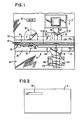
- Fig. 1 is a plan view showing a preferred embodiment of the apparatus of this invention which is designated generally as 10.
- the apparatus 10 includes a means for guiding a sheet therealong which shall be referred to as a track 12.
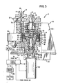
- the track 12 includes a first side wall 14 and a second side wall 16 which are spaced apart in parallel relationship to guide a sheet 18 therebetween as is best shown in Fig. 3.
- the side wall 14 (Fig. 3) has a trough portion 20 formed thereon to receive the bottom edge of the sheet 18, and it also has a flange 22 to enable it to be secured to a mounting plate 24 and to be upstanding therefrom.
- the sidewall 16 has an offset portion 26 formed therein to accommodate the trough portion 20 and to enable a flange portion 28 (joined to the offset portion 26) to be secured to the mounting plate 24 by fasteners like 25 (Fig. I).
- a conventional drive roller 30 located on one side of the track 12, and its associated pinch roller 32, located on the opposite side of track 12, cooperate to advance -or move a sheet like 18 along the track 12.
- the drive roller 30 is rotatably supported on the side wall 14 by a conventional bearing (not shown) and is rotated by a conventional drive 34 (shown only diagrammatically in Fig. 1) to advance a sheet like 18 to the right or downstream, as viewed in Fig. 1.
- the apparatus 10 also includes a drive roller 36 (Fig. 3) whose driving shaft 38 is rotatably supported on the side wall 14 by a bearing 40.
- the driving shaft 38 is rotated by a conventional drive 42 shown only schematically.
- the drive 42 may consist of a conventional motor, and driving pulleys and belts (not shown) which are operatively coupled to the drive shaft 38 to rotate the drive roller 36 in a counterclockwise direction as viewed in Fig. 1.
- the drive roller 36 has a portion of its periphery passing through an opening 44 in the side wall 14 so that the periphery extends into the space between the side walls 14 and 16.
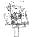
- the apparatus 10 also includes a coupling unit designated generally as 46 and is best shown in Figs. 3 and 4.
- the coupling unit 46 is rotatably supported in a "C"-shaped support which is designated generally as 48, and which is secured to the mounting plate 24.
- the coupling unit 46 has an expansible periphery 50 which is shown in a first position in Fig. 3 in which position it is uncoupled from the drive roller 36; this means that the drive roller 36 will not assist in propelling or feeding a sheet like 18 along the track.
- the drive roller 30, located further upstream in the track 12 from the drive roller 36 provides the impetus for moving the sheet along the track 12 past the drive roller 36, where additional drive rollers (like 30 but not shown) are used to move the sheet further downstream along the track 12.
- the apparatus 10 is shown in Figs. 1-3 in association with a printer designated generally as 52.
- the rate of feeding a sheet like 18 in operative association with the printer 52 is slower than the rate of feeding a sheet along the track generally.
- the feeding rate during printing is about 810 millimeters per second
- the feeding rate effected by drive roller 30, for example is about 2641 millimeters per second.
- the throughput of sheets through the apparatus 10 is about 200 documents or sheets per minute.
- drive roller 30 and drive roller 36 are constantly rotated at the necessary rotational speeds to effect the linear feeding rates mentioned in the previous paragraph. Naturally, these rates could be varied to suit different applications.
- the drive roller 30 and its associated pinch roller 32 cooperate to provide what is considered a "soft drive”, while the drive roller 36 and the expansible periphery 50 of the coupling unit 46 cooperate to provide what is considered a "hard drive”. Stated another way, the coefficient of friction between the drive roller 36 and the expansible periphery 50 is greater than that between the drive roller 30 and its associated pinch roller 32. This means that when a sheet 18 is gripped and moved by drive roller 36 and the coupling unit 46, the drive roller 30 will "slip" on the surface of the sheet 18.
- the means for rotatably mounting the coupling unit 46 in the support 48 includes a shaft member 54 (Fig. 3) having an enlarged, cylindrical, tubular portion 56 with an annular shoulder 58 on one end thereof and an open end at the opposite end thereof.
- An upper, cylindrically-shaped, rim member 60 having a central aperture, is press fitted onto shaft member 54 and abuts against the shoulder 58 as shown in Fig. 3.
- bearing 62 is positioned on the shaft member 54 to abut against the annular shoulder 64 of the upper-rim member 60.
- An annular sleeve 66 is positioned between bearing 62 and bearing 68.
- the bearings 62 and 68, along with the bushing 66 therebetween are inserted in a hole 69 in the support 48 and are retained together by a-"C"-shaped washer 70 which is fitted into a mating recess (not shown) on the shaft member 54.
- the shaft member 54 has a reduced diameter portion 72 providing an annular shoulder 74 against which a cylindrically shaped platen 76 abuts. The platen 76 is fixed to rotate with the shaft 54 and the coupling member 46 by a fastener 79.
- a feature of this invention is that the platen 76 may be adjusted axially on the reduced diameter portion 72 so as to align it with the wire plungers 78 of the print head 52, and after alignment, it may be fixed relative to the print wires 78 by a locking screw 80 which is actually displaced about 90 degrees from the position shown to facilitate the adjustment thereof.
- the coupling unit 46 also includes a lower rim member 82 having a central sleeve portion 84 which is mounted on the tubular portion 56.
- the upper rim member 60 has a peripheral skirt 86 depending therefrom, and which skirt 86 is aligned with the peripheral wall 88 (on the lower rim member 84) to receive a large elastic band which forms the expansible periphery 50 alluded to earlier herein.
- the upper rim member 60 has an annular shoulder 61 thereon and the lower rim member 82 similarly has an annular shoulder 83 thereon (Fig. 3) to retain thereon the large elastic band forming the expansible periphery 50.
- the means 89 for moving the expansible periphery 50 between the first position shown in Fig. 3 and the second position shown in Fig. 4 is best shown in Fig. 3, and it includes the wedge member 90 having a central aperture 92 enabling it to be slidably mounted on the outside diameter of the tubular portion 56.'
- the wedge member 90 has the shape of an inverted frustrum of a cone.
- Also included in the moving means 89 is-a coiled spring 94 whose ends are joined to form a circle and which spring is positioned on the annular face 96 of the lower rim member 82.
- the spring. 94 is biased to contract in diameter and thereby permit the expansible periphery 50 to assume the first position shown in Fig. 3. In this position, the expansible periphery 50 is uncoupled from the drive roller 36 so that a sheet 18 may freely pass therebetween, being driven by the upstream drive roller 30 as previously explained.
- the wedge member 90 When the expansible periphery 50 of the coupling member 46 is to be moved to the second position mentioned, the wedge member 90 is moved downwardly (as viewed in Fig. 4) by means including the shaft 98, causing the diameter of the spring 94 to increase. When the diameter of the spring 94 increases, it expands through the opening between skirt 86 and the annular face 96, forming a bulge 100 in the periphery 50, thereby increasing the effective working diameter of the coupling unit 46 to form a driving coupling between it and the drive roller 36 to advance or feed the sheet 18 therebetween in printing relationship with the printer 52.
- the wedge member 90 is moved to the position shown in Fig. 4 by a solenoid 102 having linkage connecting it with the shaft 98.
- the solenoid 102 is secured to the leg 104 of the support 48 by a threaded nut 106.
- the operating plunger 108 (Fig. 3) of the solenoid 102 has a cylindrically-shaped, tubular portion 110 formed on one end thereof, and a bearing 112 is positioned therein to abut against an annular shoulder 114 within the tubular portion 110.
- the bearing 112 is retained on the lower end 116 of the shaft 98 (which end 116 is reduced in diameter) by a "C"-shaped washer or fastener 118, and the bearing 112 is retained on the upper end by an expandible washer 120 which is retained in a mating annular recess in the tubular portion 110,
- the tubular shaft portion 56 (Fig. 3) has two diametrically opposed elongated slots 122 therein, and the shaft 98 and the wedge member 90 have aligned holes therein to permit a pin 124 to be inserted through said holes and the slots 122 (when-the coupling member 46 is in the position shown in Fig. 3) in the tubular portion 56 and through the shaft 98 (but not protruding from either end of the holes in the wedge member 90) to form a rotating, driving connection therebetween.
- This connection permits the coupling member 46 to be rotated in cooperation with the drive roller 36 when the solenoid 102 is energized to pull the wedge member 90 downwardly as viewed in Fig. 4 to expand the expansible periphery 50 as previously described.
- the lower rim member 82 (Fig. 3) may be adjusted axially on tubular shaft portion 56 relative to the upper rim member 60 and fixed on the portion 56 by the fastener 126 to provide adjustment for the position- ,ing of the spring 94.
- the wedge member 90 has an angle of 60 degrees for the conical surface, and the lower rim member 82 has a mating recess 128 therein to enable the wedge member 90 to advance therein when the solenoid 102 is energized.
- a resilient washer 130 is positioned around the operating plunger 108 of the solenoid 102 to avoid metal to metal contact between the lower end of tubular portion 110 and the top surface 103 of the threaded portion of the solenoid 102, thereby eliminating a source of noise.
- the apparatus 10 (Fig. 1) also has a source of light 132 positioned on one side of the track 12 and an associated light sensor 134- positioned on the opposite side thereof to detect the leading edge of a sheet 18 as it approaches the printer 52.
- a conventional circuit control 136 (Fig. 3) energizes the solenoid 102 to move the coupling member 46 to the second position as previously described to expand the expansible periphery 50 to form the driving connection between it-and the--drive roller-36 to drive the sheet 18 at the appropriate speed for printing by the printer 52.
- a conventional printer control 138 operatively coupled to the circuit control 136, performs the necessary formatting of data to be printed to energize the wire plungers 78 of the printer 52 to print the data in bar codes or characters, for example, on the sheet 18 as shown in Fig. 2.
- the change of state in sensor 134 which results when the trailing edge of the sheet like 18 passes thereby, may be used to de-energize the solenoid 102, for example, or the printer control 138 may provide an end of printing signal on conductor 140 (Fig. 3) to the circuit control 136 to de-energize the solenoid 102, permitting drive rollers (not shown) which are located downstream from the drive roller 36 to move the sheet 18 further downstream along track 12 at the faster rate provided by these drive rollers like drive roller 30.
- the drives 42 and 34 are also under the control of the circuit control 136.
- a ribbon (not shown) is positioned between the printer 52 and the platen 76.
- the wire plungers 78 (Fig. 3) are shown in their extended positions, and except when impacting against the ribbon and sheet 18, they are withdrawn into the printer 52.
- the ribbon and the sheet 18 provide enough resilience for the plungers 78 to impact against the metal platen 76.
- the platen 76 rotates with the coupling member 46, it provides a guiding effect in moving the sheets like 18 downstream.
- the "C" shaped support 48 which is made of metal, provides the rigidity necessary to overcome the oscillation problem mentioned earlier herein with regard to the printing. To facilitate the production of the support 48, it may be machined or formed in two pieces 48-1 and the leg T04, and these two pieces may be secured together by pins and fasteners like 142 (Fig. 4). The fasteners 142 pass through holes like hole 144 in leg 104 and are threadedly received in the piece 48-1.
- the support 48 is secured to mounting plate 24 by fasteners 146 (Fig. 1) which pass through its mounting flange 148 to the mounting plate 24.
- Another feature of the apparatus 10 is that it may be adjusted and have maintenance performed on it without having to disturb the track 12.
Landscapes
- Delivering By Means Of Belts And Rollers (AREA)
- Handling Of Cut Paper (AREA)
- Manufacture Or Reproduction Of Printing Formes (AREA)
- Handling Of Sheets (AREA)
Applications Claiming Priority (2)
| Application Number | Priority Date | Filing Date | Title |
|---|---|---|---|
| US06/333,149 US4448554A (en) | 1981-12-21 | 1981-12-21 | Sheet feeding apparatus having an expansible periphery |
| US333149 | 1999-06-14 |
Publications (3)
| Publication Number | Publication Date |
|---|---|
| EP0082708A2 true EP0082708A2 (de) | 1983-06-29 |
| EP0082708A3 EP0082708A3 (en) | 1984-11-21 |
| EP0082708B1 EP0082708B1 (de) | 1986-09-10 |
Family
ID=23301523
Family Applications (1)
| Application Number | Title | Priority Date | Filing Date |
|---|---|---|---|
| EP82306795A Expired EP0082708B1 (de) | 1981-12-21 | 1982-12-20 | Bogenzuführvorrichtung |
Country Status (5)
| Country | Link |
|---|---|
| US (1) | US4448554A (de) |
| EP (1) | EP0082708B1 (de) |
| JP (1) | JPS58110279A (de) |
| CA (1) | CA1188339A (de) |
| DE (2) | DE3273254D1 (de) |
Families Citing this family (9)
| Publication number | Priority date | Publication date | Assignee | Title |
|---|---|---|---|---|
| DE3424396A1 (de) * | 1984-07-03 | 1986-01-09 | Rubber- En Kunststoffabriek Enbi B.V., Nuth | Transportrolle |
| JPS62113150U (de) * | 1985-12-30 | 1987-07-18 | ||
| JPH0430202Y2 (de) * | 1985-12-30 | 1992-07-21 | ||
| US4723773A (en) * | 1986-10-17 | 1988-02-09 | Bell & Howell Company | Sheet feeding methods and apparatus |
| US4789151A (en) * | 1987-12-24 | 1988-12-06 | Ncr Corporation | Quickly assembled apparatus for moving documents |
| US5199701A (en) * | 1988-11-25 | 1993-04-06 | Casio Computer Co., Ltd. | Carrier apparatus using ultrasonic actuator |
| GB2238525A (en) * | 1989-11-11 | 1991-06-05 | Unisys Corp | Sprung wheel |
| JPH06329282A (ja) * | 1993-05-18 | 1994-11-29 | Canon Inc | ローラ |
| US20040075728A1 (en) * | 2002-10-21 | 2004-04-22 | Samsung Electronics Co., Ltd | Feeding roller shaft supporter for ink-jet printer |
Family Cites Families (12)
| Publication number | Priority date | Publication date | Assignee | Title |
|---|---|---|---|---|
| US1085908A (en) * | 1912-03-30 | 1914-02-03 | Robert Hoe | Web-controlling device for printing-machines. |
| GB191327153A (en) * | 1913-11-25 | 1914-04-30 | Robert Hoe | Improvements in Web Controlling Devices for Printing Machines. |
| US2341636A (en) * | 1942-01-13 | 1944-02-15 | Cottrell C B & Sons Co | Web feed roll |
| US2428316A (en) * | 1944-08-24 | 1947-09-30 | Minkow Robert | Feed roll for wire-stitching machines |
| DE958264C (de) * | 1953-06-18 | 1957-02-14 | Behn Verpackung Erwin | Vorschubwalzeneinrichtung fuer Papierverarbeitungsmaschinen |
| US3027992A (en) * | 1960-02-03 | 1962-04-03 | Burroughs Corp | Document guide device |
| GB938212A (en) * | 1963-05-10 | 1963-10-02 | Crosfield Electronics Ltd | Improvements in or relating to sheet-feeding apparatus |
| GB1136907A (en) * | 1965-03-16 | 1968-12-18 | Post Office | Improvements in or relating to conveying equipment |
| FI49814C (fi) * | 1968-01-24 | 1975-10-10 | Jagenberg Werke Ag | Laite monikerroksisen paperi-, kartonki- tms. radan yksityisten kerros ten tasaiseksi ulosvetämiseksi. |
| US3735093A (en) * | 1971-06-30 | 1973-05-22 | Ibm | Step motor and controls for non-oscillating punch/read positioning of 80-column record cards |
| DE2331125B1 (de) * | 1973-06-19 | 1974-08-01 | Maschinenfabrik Augsburg-Nuernberg Ag, 8900 Augsburg | Andrückwalze zum Herbeiführen des Anklebens einer neuen Rolle an die ablaufende Bahn insbesondere bei Rollensternen von Rotationsdruckmaschinen |
| US4279496A (en) * | 1979-05-21 | 1981-07-21 | Xerox Corporation | Belt support system |
-
1981
- 1981-12-21 US US06/333,149 patent/US4448554A/en not_active Expired - Fee Related
-
1982
- 1982-12-20 DE DE8282306795T patent/DE3273254D1/de not_active Expired
- 1982-12-20 DE DE198282306795T patent/DE82708T1/de active Pending
- 1982-12-20 JP JP57222221A patent/JPS58110279A/ja active Pending
- 1982-12-20 CA CA000418113A patent/CA1188339A/en not_active Expired
- 1982-12-20 EP EP82306795A patent/EP0082708B1/de not_active Expired
Also Published As
| Publication number | Publication date |
|---|---|
| CA1188339A (en) | 1985-06-04 |
| EP0082708B1 (de) | 1986-09-10 |
| DE82708T1 (de) | 1984-04-26 |
| US4448554A (en) | 1984-05-15 |
| JPS58110279A (ja) | 1983-06-30 |
| EP0082708A3 (en) | 1984-11-21 |
| DE3273254D1 (en) | 1986-10-16 |
Similar Documents
| Publication | Publication Date | Title |
|---|---|---|
| EP0096722B1 (de) | Blattzufuhreinrichtung | |
| EP0248075B1 (de) | Vorrichtung zum transportieren von dokumenten | |
| EP0082708B1 (de) | Bogenzuführvorrichtung | |
| US4896980A (en) | Paper advancing system for high speed printers | |
| US4072225A (en) | Combined pin feed and pressure roll forms advancement apparatus | |
| US4448407A (en) | Dual directional document drive apparatus | |
| US8341094B2 (en) | Franking machine | |
| US6098863A (en) | Web having alignment indicia and an associated web feeding and working apparatus | |
| CN1013947B (zh) | 打印机纸输送机构 | |
| EP1094022A1 (de) | Vorrichtung zum Führen und zum Handhaben einer Bahn | |
| US5040911A (en) | Paper advancing system for high speed printers | |
| US4729311A (en) | Printing apparatus including a single revolution clutch | |
| EP0915050B1 (de) | Bahn mit Führungsmarkierungen und Vorrichtung zum Führen der Bahn | |
| JP3289458B2 (ja) | 印字装置 | |
| US3516656A (en) | Means for feeding sheet paper into machines | |
| EP0145495B1 (de) | Brems- und Stoppeinrichtung für Bogen | |
| US6461066B1 (en) | Printer media feed encoder apparatus and method | |
| EP1205416A2 (de) | Bahn mit Führungsmarkierungen und Vorrichtung zum Führen der Bahn | |
| EP0130975B1 (de) | Blattzufuhreinrichtung | |
| CN109292491B (zh) | 一种自动纠偏机构及方法 | |
| JPS6323158Y2 (de) | ||
| JPH09323408A (ja) | インクジェットプリンタ | |
| KR940005211Y1 (ko) | 프린터 지송기구 | |
| KR200146636Y1 (ko) | 프린터의 용지 선택 가압 장치 | |
| GB2297315A (en) | Removing skew from paper fed to a printer |
Legal Events
| Date | Code | Title | Description |
|---|---|---|---|
| PUAI | Public reference made under article 153(3) epc to a published international application that has entered the european phase |
Free format text: ORIGINAL CODE: 0009012 |
|
| AK | Designated contracting states |
Designated state(s): DE FR GB |
|
| EL | Fr: translation of claims filed | ||
| DET | De: translation of patent claims | ||
| PUAL | Search report despatched |
Free format text: ORIGINAL CODE: 0009013 |
|
| AK | Designated contracting states |
Designated state(s): DE FR GB |
|
| 17P | Request for examination filed |
Effective date: 19850409 |
|
| 17Q | First examination report despatched |
Effective date: 19860221 |
|
| GRAA | (expected) grant |
Free format text: ORIGINAL CODE: 0009210 |
|
| AK | Designated contracting states |
Kind code of ref document: B1 Designated state(s): DE FR GB |
|
| REF | Corresponds to: |
Ref document number: 3273254 Country of ref document: DE Date of ref document: 19861016 |
|
| EN | Fr: translation not filed | ||
| PLBE | No opposition filed within time limit |
Free format text: ORIGINAL CODE: 0009261 |
|
| STAA | Information on the status of an ep patent application or granted ep patent |
Free format text: STATUS: NO OPPOSITION FILED WITHIN TIME LIMIT |
|
| 26N | No opposition filed | ||
| ET | Fr: translation filed | ||
| REG | Reference to a national code |
Ref country code: FR Ref legal event code: BR |
|
| PGFP | Annual fee paid to national office [announced via postgrant information from national office to epo] |
Ref country code: DE Payment date: 19890103 Year of fee payment: 7 |
|
| PG25 | Lapsed in a contracting state [announced via postgrant information from national office to epo] |
Ref country code: GB Effective date: 19891220 |
|
| GBPC | Gb: european patent ceased through non-payment of renewal fee | ||
| PG25 | Lapsed in a contracting state [announced via postgrant information from national office to epo] |
Ref country code: FR Effective date: 19900831 |
|
| PG25 | Lapsed in a contracting state [announced via postgrant information from national office to epo] |
Ref country code: DE Effective date: 19900901 |
|
| REG | Reference to a national code |
Ref country code: FR Ref legal event code: ST |