EP0082797A2 - Accouplement flexible double monté en parallèle - Google Patents
Accouplement flexible double monté en parallèle Download PDFInfo
- Publication number
- EP0082797A2 EP0082797A2 EP82630113A EP82630113A EP0082797A2 EP 0082797 A2 EP0082797 A2 EP 0082797A2 EP 82630113 A EP82630113 A EP 82630113A EP 82630113 A EP82630113 A EP 82630113A EP 0082797 A2 EP0082797 A2 EP 0082797A2
- Authority
- EP
- European Patent Office
- Prior art keywords
- flexible
- center member
- hub
- flexible elements
- elements
- Prior art date
- Legal status (The legal status is an assumption and is not a legal conclusion. Google has not performed a legal analysis and makes no representation as to the accuracy of the status listed.)
- Withdrawn
Links
Images

Classifications
-
- F—MECHANICAL ENGINEERING; LIGHTING; HEATING; WEAPONS; BLASTING
- F16—ENGINEERING ELEMENTS AND UNITS; GENERAL MEASURES FOR PRODUCING AND MAINTAINING EFFECTIVE FUNCTIONING OF MACHINES OR INSTALLATIONS; THERMAL INSULATION IN GENERAL
- F16D—COUPLINGS FOR TRANSMITTING ROTATION; CLUTCHES; BRAKES
- F16D3/00—Yielding couplings, i.e. with means permitting movement between the connected parts during the drive
- F16D3/50—Yielding couplings, i.e. with means permitting movement between the connected parts during the drive with the coupling parts connected by one or more intermediate members
- F16D3/78—Yielding couplings, i.e. with means permitting movement between the connected parts during the drive with the coupling parts connected by one or more intermediate members shaped as an elastic disc or flat ring, arranged perpendicular to the axis of the coupling parts, different sets of spots of the disc or ring being attached to each coupling part, e.g. Hardy couplings
- F16D3/79—Yielding couplings, i.e. with means permitting movement between the connected parts during the drive with the coupling parts connected by one or more intermediate members shaped as an elastic disc or flat ring, arranged perpendicular to the axis of the coupling parts, different sets of spots of the disc or ring being attached to each coupling part, e.g. Hardy couplings the disc or ring being metallic
-
- F—MECHANICAL ENGINEERING; LIGHTING; HEATING; WEAPONS; BLASTING
- F16—ENGINEERING ELEMENTS AND UNITS; GENERAL MEASURES FOR PRODUCING AND MAINTAINING EFFECTIVE FUNCTIONING OF MACHINES OR INSTALLATIONS; THERMAL INSULATION IN GENERAL
- F16D—COUPLINGS FOR TRANSMITTING ROTATION; CLUTCHES; BRAKES
- F16D3/00—Yielding couplings, i.e. with means permitting movement between the connected parts during the drive
- F16D3/50—Yielding couplings, i.e. with means permitting movement between the connected parts during the drive with the coupling parts connected by one or more intermediate members
- F16D3/72—Yielding couplings, i.e. with means permitting movement between the connected parts during the drive with the coupling parts connected by one or more intermediate members with axially-spaced attachments to the coupling parts
Definitions
- the couplings can be divided into two general types: first, the mechanical flexing couplings and, second, material flexing couplings.
- Mechanical flexing couplings provide flexibility by allowing the components to slide or move relative to each other. Mechanical flexing couplings generally permit greater axial misalignment between shafts than do material flexing couplings; however, there are several problems associated with them. For example, mechanical flexing couplings usually require lubrication due to the frictional sliding motion involved. Some amount of clearance between mating gear teeth is always required in the gear couplings, both in the interest of manufacturing tolerances and to allow for lubrication; this means that there will be torsional backlash as well as some lack of radial and angular rigidity.
- the material flexing group provides flexibility by having certain parts designed to flex. These flexing elements can be of various materials, such as metal, rubber, or plastic. Couplings of this type generally must be operated within the fatigue limits of the material of the flexing element. Most metals have a predictable fatigue limit and permit the establishment of definite boundaries of operation. Elastomers (rubber, plastic, etc.) usually do not have a-well-defined fatigue limit, and service life is determined primarily by the operational conditions.
- the material flexing group includes laminated-disk, diaphragm, spring, and elastomer couplings.
- the material flexing couplings overcome many of the problems associated with the mechanical flexing couplings. They do not require lubrication and have no backlash.
- a material flexing shaft coupling is that a flexible member is inserted between the shafts to permit some misalignment between the rigid members.
- a single flexing coupling may consist of a flexible disc which is connected to two hubs. The flexibility of the disc permits one hub to drive the other, even though the hubs are at an angle to each other.
- a single flexing coupling can only accept one angle of misalignment. It is quite common to encounter two angles of misalignment, for example, when the shafts lie in parallel planes. In this case, a double-flexing coupling is required.
- the logical method for adding greater misalignment capabilities to the coupling shown in Fredericks is to increase the number of flexible elements, with all the flexible elements connected in series so that each carries the entire torsional load of the coupling. For example, if a second center member and a second set of flexible elements were added to the coupling in Figure 1 of Fredericks, so that torque was transmitted from the first hub through the first set of flexible elements to the first center member, then through the second set of flexible elements to the second center member, then through the third set of flexible elements to the second hub, the new coupling would permit greater radial and axial misalignment. However, this "triple-flexing" coupling would be unstable, with the center portion of the coupling tending to be thrown out due to centrifugal force.
- the main object of the present invention is to provide a simple, compact, radially stable flexible disc coupling for high speed. high torque applications which permits substantially greater misalignment than the double-flexing disc couplings of the prior art.
- each disc pack is separately connected to its hub and to the center member, so that each disc pack carries a fraction of the total torque that is transmitted between its hub and the center member. Because each disc pack transmits less torque, the bolts connecting the disc packs to their hub and to the center member can be spaced further apart, so the discs are able to flex more, thereby permitting greater misalignment.
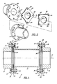
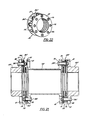
- Figure 1 shows a double-flexing coupling 10 having a first hub 12, a rigid center member 14 and a second hub 16.
- the hubs 12, 16 and center member 14 are all aligned on a longitudinal axis 18.
- the hubs 12, 16 shown here are cylindrically shaped with a flanged end, but anything which permits rigid connection to the shaft could be used in their place. For example, sometimes the end of the shaft is upset to provide a flange onto which to bolt. In that case, the end of the shaft itself would serve as.the hub. Other adaptors which serve as hubs are also known to those skilled in the art.
- the center member 14 is shown here as being cylindrically shaped with a flange at each end. This is the common shape of a center member. However, it is possible for a single rigid plate or disc to serve as a center member. Some other center members are also obvious to one skilled in the art.
- a first group of flexible elements 20 is located between the first hub 12 and the center member 14.
- a second group of flexible elements 22 is located between the center member 14 and the second hub 16.
- the first group of flexible elements 20 is made up of two separate flexible elements 24, 26. Each flexible element 24, 26 is symmetrical about the axis 18, and the flexible elements 24, 26 are connected in parallel by being separately rigidly secured to the hub 12 and to the center member 14 as will be described in more detail later.
- the second group of flexible elements 22 is made up of two separate flexible elements 28, 30 connected in parallel
- the first group of flexible elements 20 is identical to the second group of flexible elements 22, it will be understood that any description of one group of flexible elements also describes the other group.
- the two groups of flexible elements 20 . , 22 need not be identical.
- the second group 22 could be just a single flexible element which is rigidly secured to both the center member 14 and the second hub 16, or the second group 22 could comprise three flexing elements connected in parallel.
- the first and second group of flexing elements 20, 22 be the same.
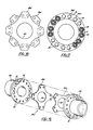
- FIG. 2 more clearly shows the first hub 12, flexible elements 24 and 26, and a broken-away portion of the center member 14.
- each flexible element 24, 26 is made up of several thin sheets of material which are laminated together. Some methods which can be used for laminating the sheets together are described in the Fredericks patent referred to earlier.
- a laminated disc such as disc 24
- the sheets which make up the disc 24 are connected to the hub 12 and to the center member 14 as a unit, so that all the sheets flex together. It is possible to separate the sheets from each other by washers or other spacers and still to connect the sheets to the hub and center member as a unit, so that the sheets flex together.
- each flexible element 24, 26 is identical to each other except that they have been rotated at an angle of 45° to each other.
- Each flexible element 24, 26 has a large central aperture 32 and four smaller apertures 34.
- the apertures 34 are all located an equal distance from the axis 18.
- aperture 34(1) of flexible member 24 it can be seen that one of the bolts 36 passes through a small opening 40 in the flanged portion of first hub 12, through a short spacer 42, through aperture 34(1), through a second small spacer 42 and is fixed in place by a nut 44, which is threaded onto the bolt 36 so as to rigidly connect the flexible element 24 to the first hub 12.
- the opening 40 is smaller than the head of the bolt 36 and that a larger opening 41 is provided in center member 14 to aid in tightening the nut 44 onto its bolt 36. It is possible to secure the flexible elements 24, 26 by rivets or other known rigid connectors, but bolts are preferred for high torque applications.
- next aperture 34(2) is used for connecting the flexible element 24 to the center member 14.
- a bolt 38 enters,through a small opening 40 of the center member 14, bypasses the flexible member 26, enters a long spacer 46, enters aperture 34(2), passes through a small spacer 42, and is secured by means of a nut 44, thereby rigidly connecting the first flexible element 24 to the center member 14.
- the long spacer 46 is used in order to firmly secure the flexible element 24 to center member 14 while leaving enough space for the flexible element 26.
- aperture 34(3) The next aperture in the flexible element 24 is aperture 34(3).
- a bolt 36 passes through a small opening 40 in the first hub 12 and secures the flexible element 24 to the hub 12 at aperture 34(3).
- aperture 34(4) is used to connect the flexible element 24 to the center member 14.
- aperture 34(5) is used to connect the flexible element 26 to the hub 12, by means of a bolt 38.
- next aperture 34(6) is used to connect the flexible element 26 with the center member 14.
- aperture 34(7) is used to connect the flexible element 26 to hub 12
- aperture 34(8) is used to connect the flexible element 26 to the center member 14.
- each flexible member 24, 26 is separately attached to the hub 12 and to the center member 14. That is, the bolt 36 which attaches the flexible member 24 to the hub 12 through the aperture 34(1) does not contact the flexible element 26, nor does it attach the flexible element 26 to any other member. Likewise, the bolt 38 which attaches the flexible element 24 to the center member 14 through aperture 34(2) bypasses the flexible element 26, due to the indentation in the outer edge of the flexible element 26.
- the group 20, consisting of the flexible elements 24 and 26, will transmit torsional load between the center member 14 and the hub 12. If the first hub 12 is acting as the driving member and the hub 16 as the driven member, torque will be transmitted from the first hub 12, through the flexible elements 24, 26, and then to the center member 14, which will then transmit torque through the second group of flexible elements to the second hub 16. If the second hub 16 is the driving member and the first hub 12 the driven member, torque will be transmitted from the center member 14 through the flexible elements 24, 26, to the first hub 12. Each flexible element 24, 26 will transmit half of the total torsional load transmitted by the group 20. Both angular and axial misalignment between the hub 12 and the center member 14 can be accommodated by the flexing of the flexible members 24 and 26. One angle of misalignment can be accommodated by the portion of the coupling shown in Figure 4, and the complete coupling, as shown in Figure 1, accommodates two angles of misalignment. This coupling is radially stable.
- FIGS 6 and 7 again illustrate the shape of the flexible elements 24 and 26 which permits them to be separately secured to their respective hub and center member.
- Figure 8 shows a part of a second embodiment of the present invention in which the center member 14a is flexibly connected to the second hub 16a by means of flexible elements 30a and 28a.
- the flexible elements 28a and 30a are made of a solid piece of material rather than a plurality of laminated sheets.
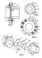
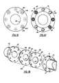
- Figures 9 through 11 illustrate the left half of a third embodiment in which the first hub 12b is flexibly attached to the center member 14b by a first group of flexible elements 20b.
- the group 20b is made up of three flexible elements 24b, 25b, 26b, instead of the two flexible elements 24 and 26 shown in the first embodiment.
- each flexible element 24b, 25b, and 26b carries one-third of the total torsional load transmitted between the first hub 12b and the center member 14b.
- Figures 12, 13 and 14 illustrate a fourth embodiment of the present invention, in which a first hub 12c is flexibly connected to a center member 14c by means of a first group of flexible elements 20c.
- the first group of flexible elements 20c is made up of two flexible elements 24c and 26c.
- Each flexible element 24c and 26c has six small openings 34c as opposed to the four small openings shown in the prior embodiments. This means that each flexible element 24c, 26c has three connections to its hub 12c and three connections to its center member 14c instead of two connections.
- the purpose of increasing the number of bolt holes 34c is to enable the coupling to transmit greater torque. However, increasing the number of bolts decreases the spacing between bolts, thereby decreasing the amount of misalignment that can be accommodated by the coupling.
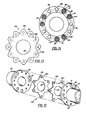
- Figures 15, 16 and 17 illustrate a fifth embodiment of the present invention in which the first hub 12d is coupled to the center member 14d by means of flexible elements 24d, 26d.
- This embodiment illustrates a double bolting arrangement, in which two rigid connections replace each single connection of the first embodiment. This sort of arrangement would be used in cases in which greater torque must be transmitted between the hub and center member.
- Figures 18, 19 and 20 illustrate a sixth embodiment of the present invention in which the first hub 12e is flexibly coupled to the center member 14e by means of flexible elements 24e and 26e.
- the discs 24e, 26e rather than shaping the outer edge of each disc 24e, 26e so that a bolt which secures one of the discs will bypass the other of the discs, the discs 24e, 26e have larger openings 35e alternating with the small openings 34e.
- a bolt which rigidly connects flexible element 24e to center member 14e will bypass flexible element 26e by passing through the larger opening 35e in flexible element 26e.
- Flexible elements 24e and 26e are separately connected as in the prior embodiments, with the only difference being the means by which the bolts which connect one flexible element bypass the other flexible element.
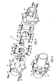
- FIGS 21 and 22 illustrate a seventh embodiment of the present invention, which is identical to the first embodiment except that each group of flexible elements 20f 22f is separately packaged in its own sandwich unit 50, for ease of assembly.
- These sandwich units are substantially the same as those shown in the Fredericks patent, which was earlier incorporated by reference, except for the parallel arrangement of the two flexible elements 20f, 22f.
- Each unit 50 includes two pilot rings 52, 54 with two flexible elements 24f, 26f between them.
- the sandwich unit 50 is held together by several fastening tubes 56 which are press fit into place.
- the coupling is made so that the outside edges of the pilot rings 52, 54 fit into lips 51.
- Bolts 36f, 38f are then inserted through the fastening tubes 56 for assembly of the coupling.
- the bolting arrangement of this embodiment is identical to that of the first embodiment.
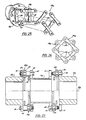
- FIGS 23, 24 and 25 illustrate an eighth embodiment of the present invention, in which each flexible element 24g, 26g is made up of four beams 58, the ends of which overlap so as to form a closed shape which is symmetrical about the longitudinal axis 18g.
- this embodiment is identical to the first embodiment.
Landscapes
- Engineering & Computer Science (AREA)
- General Engineering & Computer Science (AREA)
- Mechanical Engineering (AREA)
- Mechanical Operated Clutches (AREA)
- Transmission Devices (AREA)
- One-Way And Automatic Clutches, And Combinations Of Different Clutches (AREA)
- Pulleys (AREA)
- Joints Allowing Movement (AREA)
- Transducers For Ultrasonic Waves (AREA)
- Optical Communication System (AREA)
Applications Claiming Priority (2)
| Application Number | Priority Date | Filing Date | Title |
|---|---|---|---|
| US33353981A | 1981-12-22 | 1981-12-22 | |
| US333539 | 1994-11-01 |
Publications (2)
| Publication Number | Publication Date |
|---|---|
| EP0082797A2 true EP0082797A2 (fr) | 1983-06-29 |
| EP0082797A3 EP0082797A3 (fr) | 1983-08-17 |
Family
ID=23303225
Family Applications (1)
| Application Number | Title | Priority Date | Filing Date |
|---|---|---|---|
| EP82630113A Withdrawn EP0082797A3 (fr) | 1981-12-22 | 1982-12-07 | Accouplement flexible double monté en parallèle |
Country Status (5)
| Country | Link |
|---|---|
| EP (1) | EP0082797A3 (fr) |
| JP (1) | JPS58109722A (fr) |
| DK (1) | DK565182A (fr) |
| ES (1) | ES8401201A1 (fr) |
| NO (1) | NO824302L (fr) |
Cited By (10)
| Publication number | Priority date | Publication date | Assignee | Title |
|---|---|---|---|---|
| GB2192969A (en) * | 1986-07-26 | 1988-01-27 | Hackforth Gmbh And Co K G | A universal joint for interconnecting shafts |
| US4741722A (en) * | 1984-05-14 | 1988-05-03 | Klaus Federn | Torsionally rigid, elastically flexible shaft coupling |
| US4850933A (en) * | 1987-09-21 | 1989-07-25 | Mobil Oil Corporation | Flexible coupling |
| EP0702164A1 (fr) * | 1994-09-14 | 1996-03-20 | Rexnord Corporation | Joint transformable pour la transmission de couple |
| DE19840987A1 (de) * | 1998-09-08 | 2000-03-09 | Mayr Christian Gmbh & Co Kg | Lamelle für Wellenkupplung |
| US6443864B1 (en) * | 1999-11-08 | 2002-09-03 | Luk Lamellen Und Kupplungsbau Gmbh | Mechanism for transmitting torque between coaxial parts of transmissions and the like |
| US7597626B2 (en) * | 2004-04-23 | 2009-10-06 | Hackforth Gmbh | Membrane coupling in a compact design |
| US7727073B2 (en) * | 2006-07-19 | 2010-06-01 | Denyo Kabushiki Kaisha | Coupling plate for engine-driven generator |
| CN111577780A (zh) * | 2020-05-22 | 2020-08-25 | 中国船舶科学研究中心 | 一种弹性膜片联轴器 |
| CN113550983A (zh) * | 2021-07-28 | 2021-10-26 | 云南科力环保股份公司 | 一种分段长轴连接支撑传动装置 |
Families Citing this family (4)
| Publication number | Priority date | Publication date | Assignee | Title |
|---|---|---|---|---|
| JPS62108627U (fr) * | 1985-12-27 | 1987-07-11 | ||
| JP2684022B2 (ja) * | 1995-04-14 | 1997-12-03 | 英則 森田 | 苺の包装容器 |
| KR20030048317A (ko) * | 2001-12-12 | 2003-06-19 | 기아자동차주식회사 | 자동차의 연결축의 진동흡수장치 |
| CN112128260B (zh) * | 2020-09-22 | 2022-01-21 | 株洲时代新材料科技股份有限公司 | 一种有限空间下超低轴向刚度膜片联轴器 |
Family Cites Families (5)
| Publication number | Priority date | Publication date | Assignee | Title |
|---|---|---|---|---|
| US1348184A (en) * | 1920-08-03 | Flexible coupling | ||
| US1455242A (en) * | 1920-12-28 | 1923-05-15 | Star Motor Company | Coupling |
| US3004409A (en) * | 1958-07-31 | 1961-10-17 | Turbomachines Ltd | Flexible coupling |
| US4055966A (en) * | 1975-10-10 | 1977-11-01 | Rexnord, Inc. | Torque transmission coupling |
| GB1583945A (en) * | 1976-05-21 | 1981-02-04 | Burmah Engineering Co Ltd | Flexible couplings |
-
1982
- 1982-12-07 EP EP82630113A patent/EP0082797A3/fr not_active Withdrawn
- 1982-12-11 JP JP57216298A patent/JPS58109722A/ja active Pending
- 1982-12-21 ES ES518405A patent/ES8401201A1/es not_active Expired
- 1982-12-21 NO NO824302A patent/NO824302L/no unknown
- 1982-12-21 DK DK565182A patent/DK565182A/da not_active Application Discontinuation
Cited By (13)
| Publication number | Priority date | Publication date | Assignee | Title |
|---|---|---|---|---|
| US4741722A (en) * | 1984-05-14 | 1988-05-03 | Klaus Federn | Torsionally rigid, elastically flexible shaft coupling |
| GB2192969A (en) * | 1986-07-26 | 1988-01-27 | Hackforth Gmbh And Co K G | A universal joint for interconnecting shafts |
| US4850933A (en) * | 1987-09-21 | 1989-07-25 | Mobil Oil Corporation | Flexible coupling |
| EP0702164A1 (fr) * | 1994-09-14 | 1996-03-20 | Rexnord Corporation | Joint transformable pour la transmission de couple |
| US5944611A (en) * | 1994-09-14 | 1999-08-31 | Rexnord Corporation | Convertible coupling for a transmitting torque |
| DE19840987A1 (de) * | 1998-09-08 | 2000-03-09 | Mayr Christian Gmbh & Co Kg | Lamelle für Wellenkupplung |
| US6443864B1 (en) * | 1999-11-08 | 2002-09-03 | Luk Lamellen Und Kupplungsbau Gmbh | Mechanism for transmitting torque between coaxial parts of transmissions and the like |
| US7597626B2 (en) * | 2004-04-23 | 2009-10-06 | Hackforth Gmbh | Membrane coupling in a compact design |
| AU2005238594B2 (en) * | 2004-04-23 | 2011-03-03 | Hackforth Gmbh | Membrane coupling in a compact design |
| US7727073B2 (en) * | 2006-07-19 | 2010-06-01 | Denyo Kabushiki Kaisha | Coupling plate for engine-driven generator |
| CN111577780A (zh) * | 2020-05-22 | 2020-08-25 | 中国船舶科学研究中心 | 一种弹性膜片联轴器 |
| CN113550983A (zh) * | 2021-07-28 | 2021-10-26 | 云南科力环保股份公司 | 一种分段长轴连接支撑传动装置 |
| CN113550983B (zh) * | 2021-07-28 | 2022-11-29 | 云南科力环保股份公司 | 一种分段长轴连接支撑传动装置 |
Also Published As
| Publication number | Publication date |
|---|---|
| DK565182A (da) | 1983-06-23 |
| ES518405A0 (es) | 1983-12-01 |
| ES8401201A1 (es) | 1983-12-01 |
| NO824302L (no) | 1983-06-23 |
| EP0082797A3 (fr) | 1983-08-17 |
| JPS58109722A (ja) | 1983-06-30 |
Similar Documents
| Publication | Publication Date | Title |
|---|---|---|
| US5041060A (en) | Flexible coupling | |
| US3985000A (en) | Elastic joint component | |
| US5387157A (en) | Flexible disc-like coupling element | |
| DE10017801B4 (de) | Torsionsschwingungsdämpfer | |
| CA1125044A (fr) | Embrayage a double joint | |
| US3654775A (en) | Disc type flexible shaft coupling | |
| US4416645A (en) | Piloted flexible coupling | |
| EP2837843B1 (fr) | Couplages souples pour dispositifs de transmission de puissance | |
| US4482335A (en) | Flexible couplings | |
| CA2012991A1 (fr) | Raccord souple a membranes | |
| US2213277A (en) | Universal joint | |
| JPS6179028A (ja) | 高弾性軸継手 | |
| EP0702164A1 (fr) | Joint transformable pour la transmission de couple | |
| US2883839A (en) | Flexible drive shaft | |
| US4741722A (en) | Torsionally rigid, elastically flexible shaft coupling | |
| DE202023102375U1 (de) | Räumlich-elastische Kupplung und Kupplungsanordnung | |
| JPS58109722A (ja) | 並列配置式の2重たわみ継手 | |
| US4207758A (en) | High speed shaft flexible coupling with maximum shaft misalignment accommodation capability | |
| EP2347145B1 (fr) | Amortisseur de vibrations torsionnelles pour la chaîne cinématique d'un véhicule | |
| EP0771960A2 (fr) | Accouplement d'arlues | |
| US6135224A (en) | Vibration isolator for motor vehicle intermediate steering shaft | |
| JPH03172623A (ja) | 高弾性軸継手 | |
| EP0498235B1 (fr) | Accouplement à membrane ajourée | |
| EP0583505B1 (fr) | Accouplement d'arbres | |
| EP0063022A1 (fr) | Accouplement flexible |
Legal Events
| Date | Code | Title | Description |
|---|---|---|---|
| PUAI | Public reference made under article 153(3) epc to a published international application that has entered the european phase |
Free format text: ORIGINAL CODE: 0009012 |
|
| PUAL | Search report despatched |
Free format text: ORIGINAL CODE: 0009013 |
|
| AK | Designated contracting states |
Designated state(s): BE CH DE FR GB IT LI NL SE |
|
| AK | Designated contracting states |
Designated state(s): BE CH DE FR GB IT LI NL SE |
|
| 17P | Request for examination filed |
Effective date: 19840127 |
|
| STAA | Information on the status of an ep patent application or granted ep patent |
Free format text: STATUS: THE APPLICATION IS DEEMED TO BE WITHDRAWN |
|
| 18D | Application deemed to be withdrawn |
Effective date: 19851025 |
|
| RIN1 | Information on inventor provided before grant (corrected) |
Inventor name: FREDERICKS, WALTER A. |