EP0083067A2 - Transducteur digital de pression - Google Patents
Transducteur digital de pression Download PDFInfo
- Publication number
- EP0083067A2 EP0083067A2 EP82111875A EP82111875A EP0083067A2 EP 0083067 A2 EP0083067 A2 EP 0083067A2 EP 82111875 A EP82111875 A EP 82111875A EP 82111875 A EP82111875 A EP 82111875A EP 0083067 A2 EP0083067 A2 EP 0083067A2
- Authority
- EP
- European Patent Office
- Prior art keywords
- pressure
- resonator
- transducer
- pressure vessel
- vessel
- Prior art date
- Legal status (The legal status is an assumption and is not a legal conclusion. Google has not performed a legal analysis and makes no representation as to the accuracy of the status listed.)
- Granted
Links
Images


Classifications
-
- G—PHYSICS
- G01—MEASURING; TESTING
- G01L—MEASURING FORCE, STRESS, TORQUE, WORK, MECHANICAL POWER, MECHANICAL EFFICIENCY, OR FLUID PRESSURE
- G01L9/00—Measuring steady of quasi-steady pressure of fluid or fluent solid material by electric or magnetic pressure-sensitive elements; Transmitting or indicating the displacement of mechanical pressure-sensitive elements, used to measure the steady or quasi-steady pressure of a fluid or fluent solid material, by electric or magnetic means
- G01L9/0001—Transmitting or indicating the displacement of elastically deformable gauges by electric, electro-mechanical, magnetic or electro-magnetic means
- G01L9/0008—Transmitting or indicating the displacement of elastically deformable gauges by electric, electro-mechanical, magnetic or electro-magnetic means using vibrations
- G01L9/0022—Transmitting or indicating the displacement of elastically deformable gauges by electric, electro-mechanical, magnetic or electro-magnetic means using vibrations of a piezoelectric element
-
- G—PHYSICS
- G01—MEASURING; TESTING
- G01L—MEASURING FORCE, STRESS, TORQUE, WORK, MECHANICAL POWER, MECHANICAL EFFICIENCY, OR FLUID PRESSURE
- G01L9/00—Measuring steady of quasi-steady pressure of fluid or fluent solid material by electric or magnetic pressure-sensitive elements; Transmitting or indicating the displacement of mechanical pressure-sensitive elements, used to measure the steady or quasi-steady pressure of a fluid or fluent solid material, by electric or magnetic means
- G01L9/0026—Transmitting or indicating the displacement of flexible, deformable tubes by electric, electromechanical, magnetic or electromagnetic means
Definitions
- This invention relates to a new and improved pressure sensor and, more particularly, to a pressure transducer utilizing a force-sensitive resonator that generates a digital output.
- Existing transducers capable of generating a digital output can be classified as: (1) inherently digital (i.e., those instruments in which pressure or pressure-induced forces produce or modify a digital pattern to directly yield a digital-type output) or (2) convertably digital (i.e., those devices whose output can be transformed to a digital signal).
- the instruments generally employ pressure-sensing elements, such as liquid columns, Bourdon tubes, diaphragms, and bellows, in conjunction with detection or pickoff techniques, such as potentiometric, strain gauge, capacitive, inductive, reluc- tive, or optical.
- the liquid column devices are large, with slow response time, and sensitive to environmental factors.
- the other instruments generally produce an analog voltage output which may be transformed with an A/D converter to the desired digital signal.
- These open loop devices do not yield the required accuracy, and the A/D converter further degrades the performance and decreases reliability.
- Closed- loop or force-balance transducers have been made which yield better results due to the relatively reduced movements; however, these sensors are more complex, power consumption varies with pressure loading, and either an A/D converter or pulse-torquing techniques must be employed to obtain the digital output.
- Serious drawbacks include sensitivity to vibration, temperature, and electromagnetic interference as well as null and scale factor instabilities.
- the category of inherently digital devices includes various vibratory elements, such as strings or tapes, cylinders, diaphragms, and thin-walled capsules, as well as electronic oscillators employing inductive or capacitance sensors as part of a resonant circuit.
- the resonant circuit devices suffer from poor repeatability and hysteresis due to the relatively large pressure-induced deflections, and usually are temperature controlled due to a high thermal sensitivity. Vibration yields large error outputs, and null stability is poor due to creep, mechanical stress relaxation, and circuit component aging. Vibrating strings, cylinders, diaphragms, and capsules generally employ electromagnetic means of maintaining the oscillations, necessitating shielding from external magnetic fields.
- the vibrating strings cannot sustain any compressive forces, they must be prestressed at tension levels greater than the .maximum compressive pressure loads. Such high loads necessarily cause creep with excessively large null instability. Without a counterbalancing acceleration compensation arrangement, these transducers may be susceptible to external forces. Vibrating diaphragm, cylinder and capsule transducers are sensitive to temperature, vibration, and gas composition. Most of these devices cannot measure liquid pressures because the sensing element must work in a vacuum. Null and scale factor instabilities are a general problem since large frequency drifts of vibratory systems such as these are common.
- Quartz resonator pressure gauges have been built which have an inherently digital output, as described in Karrer et al, "A Quartz Resonator Pressure Transducer,” IEEE Trans. Ind. Elec. and Control Instr., Vol. 16, 44 (1969), and EerNisse, "Quartz Resonator Pressure Gauge: Design and Fabrication Technology,” Sandia Laboratories SAND 78-2264 (Dec. 1978). These devices consist of a thickness-shear mode plate resonator enclosed by two hollowed-out quartz end caps. Hydrostatic pressure applied to the transducer generates a radially directed force around the perimeter of the resonator and changes the resonator's frequency of oscillation.
- transducers have a relatively low sensitivity to the applied load; i.e., the fractional frequency change with full-scale applied pressure is quite small (generally a fraction of one percent).
- the low sensitivity means that the susceptibility to environmental errors, such as temperature, is large.
- These transducers are also expensive and difficult to fabricate.
- quartz crystal pressure transducers As described in Paros, "Digital Pressure Transducers,” Measurements and Data, Issue 56, Vol. 10, No. 2 (1976), quartz crystal pressure transducers have been developed in which a bellows/suspension system arrangement applies pressure-induced stress to a flexurally vibrating resonator. Although these resonators have a much greater force sensitivity than the aforementioned thickness-shear mode crystals, the overall transducer is limited in pressure range, temperature capability, and interface with corrosive pressure media.
- the prior art devices cannot meet the desired objectives of an inherently digital-type output, high sensitivity, excellent accuracy and stability, low power consumption, small size and weight, fast response time, small environmental errors, ability to measure corrosive fluid pressures, high reliability, and low cost.
- a load-sensitive resonator In an unstressed condition, under constant environmental conditions, a load-sensitive resonator has a unique resonant frequency determined by its dimensions and material composition. The resonant frequency of a flexurally vibrating resonator increases under tensile loading and decreases under compressive loading. A number of load-sensitive transducers utilizing this principle have been developed.
- a number of conventional devices utilize a non- resonant displacement-sensing device to measure displacement of a Bourdon tube responsive to variations in applied pressure.
- U.S. Patent No. 3,013,234 describes a device which measures the pressure-induced displacement of a Bourdon tube by mounting a capacitor plate or resistive winding on the tube so that its position with respect to a second capacitor plate or potentiometer wiper varies in accordance with applied pressure.
- U.S. Patent No. 2,877,325 discloses a pressure transducer in which a potentiometer wiper is mounted at the end of a Bourdon tube so that it moves along the potentiometer winding responsive to pressure variations.
- One or more load-sensitive resonators are coupled to a pressure vessel of nonsymmetrical configuration such that pressure-induced bending stress/strain changes the resonators' frequency of vibration.
- the nonsymmetrical configuration may assume either a nonsymmetrical construction, such as pressure vessels having a spring constant that varies around its circumference, or a nonsymmetrical shape, such as a_ curved pressure vessel.
- the resonator is mounted directly on the pressure vessel.
- the forces generated by the aforementioned pressure vessels may be directly applied to resonators mounted between the pressure vessel and base structures.
- the forces generated by the aforementioned pressure vessels may be applied to intermediate pivotally mounted structures to which the resonators are attached.
- a pressure vessel enclosing a load-sensitive resonator is suspended from a base structure such that pressure-induced loads are applied to the resonator.
- the present invention is equally applicable to load-sensitive resonators of various shapes and configurations; however, for simplicity and clarity, only the application to flexurally vibrating, force-sensitive beam and closed-end tuning fork devices will be described in detail, it being understood that the same or similar principles apply in the general case.
- Fig. 1 illustrates a conventional single-beam force transducer 2 with integral mounting isolation, as disclosed in the aforementioned patent to Weisbord.
- the transducer 2 consists of a flexurally vibrating center beam 4, two sets of isolator masses 6, and isolator springs 8 extending from each end of the beam 4 to mounting surfaces 10. Axial forces, applied along the longitudinal axis of the transducer 2, stress the vibrating beam 4, thereby changing its resonant frequency in accordance with the magnitude of the applied loads.
- the isolator masses 6 and isolator springs 8 are designed to decouple the reactive forces and moments generated by the beam 4 from mounts 10, thus reducing the energy losses.
- the transducer 2 has a high "Q" so that its resonant frequency is an accurate representation of the applied forces.
- the beam 4 may be driven at its resonant frequency using electrodes 12 and oscillator circuitry in any conventional manner, such as is described in U.S. Patent No. 3,479,536, issued to Norris.
- Fig. 2 is a plan view of a conventional closed-end tuning fork 20, as described in the aforementioned patent to Erdley..
- This device 20 achieves low energy loss, high "Q" operation by driving a pair of closely matched tines 22, 180 degrees out of phase, thus cancelling the reactive moments and forces which might be transmitted to a mount 24 from which the tines 22 project.
- the resonant frequency in Hertz, f o of a unstressed, fixed-ended, flexurally vibrating beam of length L, thickness t, width b, modulus of elasticity E, and density d, is given by the formula:
- the resonant frequency is generally a nonlinear function of the applied load F
- the first-order load sensitivity S F defined as the fractional frequency change with applied load, may be calculated as:
- the quantitative relationships between resonant frequency, applied load, and resonator dimensions and composition can be determined from the above formulae.
- pressure-induced mechanical stress may be applied to load-sensitive resonators to form digital pressure transducers.
- Equation 2 may be rewritten in terms of resonator stress
- the resonator stress equals the modulus of elasticity E times the resonator strain e
- Equation 3 may be written as:
- the load on the resonator may be either compressive or tensile, causing a frequency decrease or increase, respectively. If two resonators are attached to the load generator in either a dual bending or push-pull (compression-tension) arrangement, then performance advantages may result by computing the difference (beat) frequency between the two resonators or the difference between the squares of the two frequencies.
- the aforementioned performance advantages include an improvement in linearity as well as compensation for effects due to temperature, humidity, drift, etc., which affect both resonators equally.
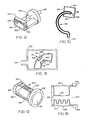
- Fig. 3 illustrates a curved pressure vessel 30 of noncircular cross-section with closed end 32.
- This pressure vessel is known as a C-shaped Bourdon tube and is similar to Bourdon tubes commonly used as the sensing element in mechanical qauges and analog output transducers.
- Bourdon tubes used in mechanical gauges and analog output transducers are usually formed by a significantly longer tube arranged in multiple coils so that the end of the tube is displaced a considerable distance responsive to pressure variations. This is necessary to allow the relatively insensitive and inaccurate mechanical gauges and analog transducers to measurably respond to the pressure-induced movement of the tube.
- load-sensitive resonators may be attached to restrain the uncurling and bending forces to provide a measure of the applied pressure.
- Fig. 4 illustrates an embodiment of this invention in which a load-sensitive resonator 40, with mounting pads 42, is attached between the base 44 and the closed end 46 of the C-shaped Bourdon tube 48.
- the flattened tube 48 When pressure is applied to port 50, the flattened tube 48 generates forces tending to uncurl or straighten the pressure vessel. These forces are resisted by the resonator 40, whose change in frequency of oscillation is a measure of the applied pressure.
- the resonator 40 is placed in tension with pressure applied to port 50. If the resonator were attached between closed end 46 and fixed base 52, then applied pressure would compress the resonator.
- a push-pull, two-resonator system could be constructed with a resonator undergoing compression mounted between points 46 and 52 and a resonator undergoing tension mounted between points 46 and 44.
- Fig. 5A illustrates an embodiment of this invention in which a U-shaped Bourdon tube 62 with a centrally located pressure port 64 applies pressure-induced tensile loads to a resonator 66 which is attached between the mounts 68 at the closed ends of the pressure vessel. If a resonator were attached between one of the mounts 68 and its respective fixed base 70, then it would be compressed under applied pressure-induced loading. Thus a multiple-resonator, push-pull system could also be constructed.
- Fig. 5B shows an embodiment in which pressure applied to port 72 communicates internally to flattened tubes 74 to cause compressive loading on resonator 76.
- Fig. 6 illustrates an embodiment of this invention in which pressure applied to the inlet port 80 of a curved, noncircular cross-section pressure vessel 82 generates an upward force on flexible linkage 84, which is connected between the closed end 90 of the pressure vessel and pivotally mounted suspension arm 86.
- the pressure-generated force on suspension arm 86 causes a torque about pivot 88.
- Pivot 88 is very flexible about an axis perpendicular to the plane of the illustration, but is relatively stiff in the cross-axis directions.
- the torque is restrained by load-sensitive resonator 96, which is attached between mounting pad 92 on the suspension arm 86 and mounting pad 94 on the fixed base.
- pressure-induced compressive loading on the resonator changes its frequency of oscillation, which is a measure of the applied pressure. If a load-sensitive resonator were attached between mounting pads 92 and 98, then the resonator would be placed under tension with applied pressure. Thus it is also possible to have a two-resonator, push-pull arrangement. Different pressure range instruments may be constructed by varying the lever arm ratio on the pivotally mounted suspension arm 86 (i.e., the ratio of the horizontal distance between linkage 84 and pivot 88, and the horizontal distance between pivot 88 and resonator 96).
- the tubes may be coiled in a helical pattern or spiral configuration.
- a load-sensitive resonator restraining the motion, the total excursion under full-scale load is only several micrometers.
- An advantage of a multiple-turn pressure vessel is to reduce its overall reactive mechanical spring rate, which could degrade the resonator performance.
- Fig. 7 depicts a spiral Bourdon tube 102, with pressure inlet port 104 and resonator 106 attached between closed end 108 and fixed base 110.
- pressure vessel tends to uncoil and applies a tensile load to resonator 106, whose frequency change is a measure of the applied pressure.
- compressive loading arrangements and multiple-resonator, push-pull configurations are also possible.
- Fig. 8 depicts a pressure vessel 120 of noncircular cross-section which has been formed into a helical pattern. Pressure applied to port 122 causes vessel 120 to exert an unwinding force on resonator 124, which is attached between closed end 126 and fixed base 128.
- Fig. 9 illustrates a digital pressure transducer employing a push-pull, dual-resonator sensing system with a torsionally acting, flattened, and twisted pressure vessel.
- the tube 142 exerts a torque as it tries to untwist.
- Arm 144 attached to the closed end of tube 142, exerts a tensile load on resonator 146 and a compressive load on resonator 148, where both resonators are spaced apart from the axis of twisting and attached between arm 144 and fixed base 150.
- the difference between the frequencies of oscillation of resonators 146 and 148 is a measure of the applied pressure.
- alternate configurations may employ a single load-sensitive resonator operating in either compression or tension.
- a torsional support may be employed at position 152 which allows free rotation about the twisting axis but offers relatively rigid support in other directions.
- Fig. 10 illustrates an embodiment of this invention in which the pressure-induced bending strain of a curved, closed-end, noncircular cross-section pressure vessel loads a force-sensitive resonator.
- a compressional strain is applied to load-sensitive resonator 164 through the attachment mounts 166.
- the pressure-induced strain causes a frequency change in the resonator according to Equation 4 of this text, thus providing a measure of the pressure.
- Tensile strain may be applied to a resonator 168 by attaching it to mounts 166 inside the curve of the pressure vessel 162.
- the beat frequency between resonator 168 in tension and resonator 164 in compression is a measure of the applied pressure and may also serve to compensate sources of error common to both resonators.
- the scale factors (pressure-loaded sensitivities) of resonators 164 and 168 may be made equal by adding or removing material from the top or bottom of extension 169, which transmits the bending force from tube 162 through mounts 166 to the resonators. Removal or addition of material to one side of extension 169 essentially moves the neutral axis of bending towards one resonator and away from the other resonator.
- the scale factors of resonators 164 and 168 may also be adjusted through changes in the rigidity of one side of mounts 166 such that the bending strain is not completely transmitted to one or the other of the resonators.
- a resonator 182 may be attached with mounts 184 to the side of pressure vessel 174, having the larger radius of curvature. Under applied pressure, compressive strain/stress is generated on resonator 182. Thus, a push-pull, dual-resonator arrangement is also possible with this configuration.
- Fig. 12 illustrates an embodiment of this invention in which the closed-end, noncircular cross-section pressure vessel has the form of a partial bellows with a flat section to produce bending loads.
- the pressure vessel has an open port 190 and is attached and sealed to fixed structure 192. Closed end 194 contains the applied pressure within the pressure vessel. A series of flexible corrugations or convolutions 196 partially circumscribe the pressure vessel and interface to a relatively flat portion 198.
- Load-sensitive resonator 200 is attached between closed end 194 and fixed structure 192 through mounts 202. When pressure is applied to inlet port 190, bending loads are generated about a neutral axis parallel to flat portion 198. These loads compress resonator 200 and change its frequency of oscillation, which is a measure of the applied pressure.
- Fig. 13 illustrates an embodiment of this invention utilizing a push-pull, dual-resonator system in conjunction with a pressure vessel similar to that depicted in Fig. 12.
- inlet port 210 As pressure is applied to inlet port 210, bending forces are generated about an axis approximately parallel to flat portion 212 due to the asymmetry associated with partially circumscribed convolutions 214 and flat portion 212.
- the bending forces simultaneously compress resonator 216 and tense resonator 218, which are mounted between the pressure vessel's closed end 220 and fixed structure mounts 222.
- the difference frequency between resonators 216 and 218 is a measure of the applied pressure.
Landscapes
- Physics & Mathematics (AREA)
- General Physics & Mathematics (AREA)
- Electromagnetism (AREA)
- Measuring Fluid Pressure (AREA)
Priority Applications (1)
| Application Number | Priority Date | Filing Date | Title |
|---|---|---|---|
| AT82111875T ATE41518T1 (de) | 1981-12-28 | 1982-12-21 | Digitaler druckwandler. |
Applications Claiming Priority (2)
| Application Number | Priority Date | Filing Date | Title |
|---|---|---|---|
| US334649 | 1981-12-28 | ||
| US06/334,649 US4455874A (en) | 1981-12-28 | 1981-12-28 | Digital pressure transducer |
Publications (3)
| Publication Number | Publication Date |
|---|---|
| EP0083067A2 true EP0083067A2 (fr) | 1983-07-06 |
| EP0083067A3 EP0083067A3 (en) | 1984-08-01 |
| EP0083067B1 EP0083067B1 (fr) | 1989-03-15 |
Family
ID=23308151
Family Applications (1)
| Application Number | Title | Priority Date | Filing Date |
|---|---|---|---|
| EP82111875A Expired EP0083067B1 (fr) | 1981-12-28 | 1982-12-21 | Transducteur digital de pression |
Country Status (6)
| Country | Link |
|---|---|
| US (1) | US4455874A (fr) |
| EP (1) | EP0083067B1 (fr) |
| JP (1) | JPS58118935A (fr) |
| AT (1) | ATE41518T1 (fr) |
| CA (1) | CA1189720A (fr) |
| DE (1) | DE3279540D1 (fr) |
Cited By (2)
| Publication number | Priority date | Publication date | Assignee | Title |
|---|---|---|---|---|
| WO1998029721A1 (fr) * | 1996-12-31 | 1998-07-09 | Honeywell Inc. | Detecteur de pression absolue a microfaisceau resonant a couche mince |
| WO2011098838A1 (fr) | 2010-02-15 | 2011-08-18 | Smart Fibres Limited | Appareil de contrôle de pression de fluide |
Families Citing this family (58)
| Publication number | Priority date | Publication date | Assignee | Title |
|---|---|---|---|---|
| US4739664A (en) * | 1987-02-20 | 1988-04-26 | Ford Motor Company | Absolute fluid pressure sensor |
| US5070736A (en) * | 1990-01-05 | 1991-12-10 | Lew Hyok S | Differential pressure sensor with read-out device |
| WO1991017416A1 (fr) * | 1990-03-01 | 1991-11-14 | Panex Corporation | Transducteur resonnant non piezoelectrique |
| US5655357A (en) * | 1995-05-02 | 1997-08-12 | Tilia International, Inc. | Exhaust flow rate vacuum sensor |
| EP0753728A3 (fr) * | 1995-07-14 | 1998-04-15 | Yokogawa Electric Corporation | Dispositif sémi-conducteur pour mesurer la pression différentielle |
| US6278379B1 (en) * | 1998-04-02 | 2001-08-21 | Georgia Tech Research Corporation | System, method, and sensors for sensing physical properties |
| US6508131B2 (en) | 1999-05-14 | 2003-01-21 | Rosemount Inc. | Process sensor module having a single ungrounded input/output conductor |
| US6295875B1 (en) | 1999-05-14 | 2001-10-02 | Rosemount Inc. | Process pressure measurement devices with improved error compensation |
| US6279405B1 (en) | 1999-06-07 | 2001-08-28 | Kenneth K. Clark | Apparatus and method for a pressure monitoring device |
| US6497152B2 (en) | 2001-02-23 | 2002-12-24 | Paroscientific, Inc. | Method for eliminating output discontinuities in digital pressure transducers and digital pressure transducer employing same |
| US6516672B2 (en) | 2001-05-21 | 2003-02-11 | Rosemount Inc. | Sigma-delta analog to digital converter for capacitive pressure sensor and process transmitter |
| US6839546B2 (en) | 2002-04-22 | 2005-01-04 | Rosemount Inc. | Process transmitter with wireless communication link |
| US7131250B2 (en) | 2002-10-04 | 2006-11-07 | Jcs/Thg, Llp | Appliance for vacuum sealing food containers |
| US7003928B2 (en) | 2002-10-04 | 2006-02-28 | Jcs/Thg, Llc | Appliance for vacuum sealing food containers |
| US7076929B2 (en) | 2002-10-04 | 2006-07-18 | Jcs/Thg, Llc | Appliance for vacuum sealing food containers |
| US8145180B2 (en) | 2004-05-21 | 2012-03-27 | Rosemount Inc. | Power generation for process devices |
| US8160535B2 (en) * | 2004-06-28 | 2012-04-17 | Rosemount Inc. | RF adapter for field device |
| US7262693B2 (en) * | 2004-06-28 | 2007-08-28 | Rosemount Inc. | Process field device with radio frequency communication |
| US7680460B2 (en) * | 2005-01-03 | 2010-03-16 | Rosemount Inc. | Wireless process field device diagnostics |
| US7334484B2 (en) * | 2005-05-27 | 2008-02-26 | Rosemount Inc. | Line pressure measurement using differential pressure sensor |
| RU2389056C2 (ru) | 2005-06-27 | 2010-05-10 | Роузмаунт Инк. | Полевое устройство с радиочастотной связью, в которой потребляемая мощность динамически регулируется |
| US7379792B2 (en) * | 2005-09-29 | 2008-05-27 | Rosemount Inc. | Pressure transmitter with acoustic pressure sensor |
| US7415886B2 (en) * | 2005-12-20 | 2008-08-26 | Rosemount Inc. | Pressure sensor with deflectable diaphragm |
| US7308830B2 (en) * | 2006-01-26 | 2007-12-18 | Rosemount Inc. | Pressure sensor fault detection |
| US7685882B1 (en) * | 2006-05-08 | 2010-03-30 | Diversitech Corporation | Heating and air conditioning service gauge |
| US7891250B2 (en) * | 2007-04-04 | 2011-02-22 | American Air Liquide, Inc. | Method and apparatus to digitize pressure gauge information |
| US8898036B2 (en) | 2007-08-06 | 2014-11-25 | Rosemount Inc. | Process variable transmitter with acceleration sensor |
| US7484416B1 (en) | 2007-10-15 | 2009-02-03 | Rosemount Inc. | Process control transmitter with vibration sensor |
| JP2010019826A (ja) * | 2008-03-25 | 2010-01-28 | Epson Toyocom Corp | 圧力センサ |
| JP2009258085A (ja) * | 2008-03-25 | 2009-11-05 | Epson Toyocom Corp | 圧力センサおよびその製造方法 |
| JP2010019827A (ja) * | 2008-06-11 | 2010-01-28 | Epson Toyocom Corp | 圧力センサー |
| JP2010019829A (ja) * | 2008-06-11 | 2010-01-28 | Epson Toyocom Corp | 圧力センサー |
| JP2010019828A (ja) * | 2008-06-11 | 2010-01-28 | Epson Toyocom Corp | 圧力センサー用ダイアフラムおよび圧力センサー |
| US8694060B2 (en) | 2008-06-17 | 2014-04-08 | Rosemount Inc. | Form factor and electromagnetic interference protection for process device wireless adapters |
| US8929948B2 (en) | 2008-06-17 | 2015-01-06 | Rosemount Inc. | Wireless communication adapter for field devices |
| CA2726534C (fr) * | 2008-06-17 | 2016-03-22 | Rosemount Inc. | Adaptateur rf pour dispositif de terrain a derivation de courant en boucle |
| CN102067048B (zh) | 2008-06-17 | 2017-03-08 | 罗斯蒙特公司 | 用于具有可变压降的现场设备的rf适配器 |
| CN102084307B (zh) | 2008-06-17 | 2014-10-29 | 罗斯蒙特公司 | 用于具有低压本质安全钳的现场设备的rf适配器 |
| JP5187529B2 (ja) * | 2008-07-22 | 2013-04-24 | セイコーエプソン株式会社 | 圧力センサー |
| US8327713B2 (en) | 2008-12-03 | 2012-12-11 | Rosemount Inc. | Method and apparatus for pressure measurement using magnetic property |
| US7870791B2 (en) * | 2008-12-03 | 2011-01-18 | Rosemount Inc. | Method and apparatus for pressure measurement using quartz crystal |
| US7954383B2 (en) * | 2008-12-03 | 2011-06-07 | Rosemount Inc. | Method and apparatus for pressure measurement using fill tube |
| JP4756394B2 (ja) * | 2009-03-04 | 2011-08-24 | セイコーエプソン株式会社 | 圧力センサー |
| US8626087B2 (en) | 2009-06-16 | 2014-01-07 | Rosemount Inc. | Wire harness for field devices used in a hazardous locations |
| US9674976B2 (en) * | 2009-06-16 | 2017-06-06 | Rosemount Inc. | Wireless process communication adapter with improved encapsulation |
| US8606426B2 (en) * | 2009-10-23 | 2013-12-10 | Academia Sinica | Alignment and anti-drift mechanism |
| WO2011106011A1 (fr) * | 2010-02-26 | 2011-09-01 | Diversitech Corporation | Manomètre de monteur pour dispositif de chauffage et de climatisation |
| US8429978B2 (en) | 2010-03-30 | 2013-04-30 | Rosemount Inc. | Resonant frequency based pressure sensor |
| US8429976B2 (en) * | 2010-05-19 | 2013-04-30 | Schlumberger Technology Corporation | Low cost resonator-based pressure transducer |
| US8234927B2 (en) | 2010-06-08 | 2012-08-07 | Rosemount Inc. | Differential pressure sensor with line pressure measurement |
| US8132464B2 (en) | 2010-07-12 | 2012-03-13 | Rosemount Inc. | Differential pressure transmitter with complimentary dual absolute pressure sensors |
| US10761524B2 (en) | 2010-08-12 | 2020-09-01 | Rosemount Inc. | Wireless adapter with process diagnostics |
| US9038263B2 (en) | 2011-01-13 | 2015-05-26 | Delaware Capital Formation, Inc. | Thickness shear mode resonator sensors and methods of forming a plurality of resonator sensors |
| US9310794B2 (en) | 2011-10-27 | 2016-04-12 | Rosemount Inc. | Power supply for industrial process field device |
| US8752433B2 (en) | 2012-06-19 | 2014-06-17 | Rosemount Inc. | Differential pressure transmitter with pressure sensor |
| US9048901B2 (en) | 2013-03-15 | 2015-06-02 | Rosemount Inc. | Wireless interface within transmitter |
| RU174922U1 (ru) * | 2016-07-15 | 2017-11-20 | Валерий Владимирович Коваленко | Первичный преобразователь давления, влажности и молекулярной массы газа |
| US10119874B2 (en) | 2016-07-28 | 2018-11-06 | Fluke Corporation | Amorphous quartz pressure transducer |
Family Cites Families (7)
| Publication number | Priority date | Publication date | Assignee | Title |
|---|---|---|---|---|
| GB1034363A (en) * | 1961-12-18 | 1966-06-29 | Dowty Technical Dev Ltd | Pressure transducer |
| US3479536A (en) * | 1967-03-14 | 1969-11-18 | Singer General Precision | Piezoelectric force transducer |
| US3470400A (en) * | 1967-12-21 | 1969-09-30 | Singer General Precision | Single beam force transducer with integral mounting isolation |
| US3618391A (en) * | 1969-11-14 | 1971-11-09 | Ilia Yakovlevich Rivkin | Pressure transducer |
| JPS502855U (fr) * | 1973-05-19 | 1975-01-13 | ||
| JPS5856404B2 (ja) * | 1978-11-29 | 1983-12-14 | 横河電機株式会社 | 水晶トランスデュサ |
| EP0037654B1 (fr) * | 1980-04-03 | 1984-09-26 | Giers | Appareil actionné par la pression d'un fluide |
-
1981
- 1981-12-28 US US06/334,649 patent/US4455874A/en not_active Expired - Lifetime
-
1982
- 1982-10-27 CA CA000414301A patent/CA1189720A/fr not_active Expired
- 1982-12-21 DE DE8282111875T patent/DE3279540D1/de not_active Expired
- 1982-12-21 EP EP82111875A patent/EP0083067B1/fr not_active Expired
- 1982-12-21 AT AT82111875T patent/ATE41518T1/de not_active IP Right Cessation
- 1982-12-24 JP JP57235098A patent/JPS58118935A/ja active Pending
Cited By (3)
| Publication number | Priority date | Publication date | Assignee | Title |
|---|---|---|---|---|
| WO1998029721A1 (fr) * | 1996-12-31 | 1998-07-09 | Honeywell Inc. | Detecteur de pression absolue a microfaisceau resonant a couche mince |
| US5808210A (en) * | 1996-12-31 | 1998-09-15 | Honeywell Inc. | Thin film resonant microbeam absolute pressure sensor |
| WO2011098838A1 (fr) | 2010-02-15 | 2011-08-18 | Smart Fibres Limited | Appareil de contrôle de pression de fluide |
Also Published As
| Publication number | Publication date |
|---|---|
| EP0083067B1 (fr) | 1989-03-15 |
| ATE41518T1 (de) | 1989-04-15 |
| DE3279540D1 (en) | 1989-04-20 |
| US4455874A (en) | 1984-06-26 |
| JPS58118935A (ja) | 1983-07-15 |
| EP0083067A3 (en) | 1984-08-01 |
| CA1189720A (fr) | 1985-07-02 |
Similar Documents
| Publication | Publication Date | Title |
|---|---|---|
| US4455874A (en) | Digital pressure transducer | |
| US4751849A (en) | Force-sensitive resonator load cell | |
| US4881408A (en) | Low profile accelerometer | |
| US6826960B2 (en) | Triaxial acceleration sensor | |
| US6595054B2 (en) | Digital angular rate and acceleration sensor | |
| AU677434B2 (en) | Static pressure compensation of resonant integrated microbeam sensors | |
| US4891982A (en) | Temperature compensation of a steady-state accelerometer | |
| US4258565A (en) | Force detector | |
| US4079624A (en) | Load washer transducer assembly | |
| US3465597A (en) | Vibrating-column accelerometer | |
| US6497152B2 (en) | Method for eliminating output discontinuities in digital pressure transducers and digital pressure transducer employing same | |
| EP0593676A4 (en) | Method and apparatus for measurement of forces and pressures using tensioned bellows | |
| US5036715A (en) | Cantilevered force sensing assembly utilizing one or two resonating force sensing devices | |
| EP0053341A2 (fr) | Capteur de température digital | |
| US4091679A (en) | Vibrating quartz accelerometer | |
| EP0327524A2 (fr) | Appareil sensible à une pression différentielle | |
| US4459042A (en) | Vibratory digital temperature sensor | |
| Paros | Precision Digital Pressure | |
| US3995247A (en) | Transducers employing gap-bridging shim members | |
| US3242738A (en) | Pressure-responsive instruments | |
| US3968693A (en) | Open-loop differential-pressure transmitter | |
| JPS5858603B2 (ja) | 変位変換器 | |
| US4651569A (en) | Torque tube digital differential pressure sensor | |
| US3427885A (en) | Differential pressure transducer | |
| CN1082183C (zh) | 石英谐振式力/称重传感器 |
Legal Events
| Date | Code | Title | Description |
|---|---|---|---|
| PUAI | Public reference made under article 153(3) epc to a published international application that has entered the european phase |
Free format text: ORIGINAL CODE: 0009012 |
|
| AK | Designated contracting states |
Designated state(s): AT BE CH DE FR GB IT LI LU NL SE |
|
| PUAL | Search report despatched |
Free format text: ORIGINAL CODE: 0009013 |
|
| AK | Designated contracting states |
Designated state(s): AT BE CH DE FR GB IT LI LU NL SE |
|
| 17P | Request for examination filed |
Effective date: 19841210 |
|
| 17Q | First examination report despatched |
Effective date: 19860411 |
|
| GRAA | (expected) grant |
Free format text: ORIGINAL CODE: 0009210 |
|
| AK | Designated contracting states |
Kind code of ref document: B1 Designated state(s): AT BE CH DE FR GB IT LI LU NL SE |
|
| PG25 | Lapsed in a contracting state [announced via postgrant information from national office to epo] |
Ref country code: SE Effective date: 19890315 Ref country code: NL Effective date: 19890315 Ref country code: LI Effective date: 19890315 Ref country code: IT Free format text: LAPSE BECAUSE OF FAILURE TO SUBMIT A TRANSLATION OF THE DESCRIPTION OR TO PAY THE FEE WITHIN THE PRESCRIBED TIME-LIMIT;WARNING: LAPSES OF ITALIAN PATENTS WITH EFFECTIVE DATE BEFORE 2007 MAY HAVE OCCURRED AT ANY TIME BEFORE 2007. THE CORRECT EFFECTIVE DATE MAY BE DIFFERENT FROM THE ONE RECORDED. Effective date: 19890315 Ref country code: CH Effective date: 19890315 Ref country code: BE Effective date: 19890315 Ref country code: AT Effective date: 19890315 |
|
| REF | Corresponds to: |
Ref document number: 41518 Country of ref document: AT Date of ref document: 19890415 Kind code of ref document: T |
|
| REF | Corresponds to: |
Ref document number: 3279540 Country of ref document: DE Date of ref document: 19890420 |
|
| REG | Reference to a national code |
Ref country code: CH Ref legal event code: PL |
|
| ET | Fr: translation filed | ||
| NLV1 | Nl: lapsed or annulled due to failure to fulfill the requirements of art. 29p and 29m of the patents act | ||
| PG25 | Lapsed in a contracting state [announced via postgrant information from national office to epo] |
Ref country code: LU Free format text: LAPSE BECAUSE OF NON-PAYMENT OF DUE FEES Effective date: 19891231 |
|
| PLBE | No opposition filed within time limit |
Free format text: ORIGINAL CODE: 0009261 |
|
| STAA | Information on the status of an ep patent application or granted ep patent |
Free format text: STATUS: NO OPPOSITION FILED WITHIN TIME LIMIT |
|
| 26N | No opposition filed | ||
| PGFP | Annual fee paid to national office [announced via postgrant information from national office to epo] |
Ref country code: FR Payment date: 19981202 Year of fee payment: 17 |
|
| PGFP | Annual fee paid to national office [announced via postgrant information from national office to epo] |
Ref country code: GB Payment date: 19981203 Year of fee payment: 17 |
|
| PGFP | Annual fee paid to national office [announced via postgrant information from national office to epo] |
Ref country code: DE Payment date: 19981204 Year of fee payment: 17 |
|
| PG25 | Lapsed in a contracting state [announced via postgrant information from national office to epo] |
Ref country code: GB Free format text: LAPSE BECAUSE OF NON-PAYMENT OF DUE FEES Effective date: 19991221 |
|
| GBPC | Gb: european patent ceased through non-payment of renewal fee |
Effective date: 19991221 |
|
| PG25 | Lapsed in a contracting state [announced via postgrant information from national office to epo] |
Ref country code: FR Free format text: LAPSE BECAUSE OF NON-PAYMENT OF DUE FEES Effective date: 20000831 |
|
| PG25 | Lapsed in a contracting state [announced via postgrant information from national office to epo] |
Ref country code: DE Free format text: LAPSE BECAUSE OF NON-PAYMENT OF DUE FEES Effective date: 20001003 |
|
| REG | Reference to a national code |
Ref country code: FR Ref legal event code: ST |