EP0083082A2 - Procédé et dispositif pour mesurer la longueur d'une droite ou d'une courbe - Google Patents
Procédé et dispositif pour mesurer la longueur d'une droite ou d'une courbe Download PDFInfo
- Publication number
- EP0083082A2 EP0083082A2 EP82111940A EP82111940A EP0083082A2 EP 0083082 A2 EP0083082 A2 EP 0083082A2 EP 82111940 A EP82111940 A EP 82111940A EP 82111940 A EP82111940 A EP 82111940A EP 0083082 A2 EP0083082 A2 EP 0083082A2
- Authority
- EP
- European Patent Office
- Prior art keywords
- sensor
- movement
- marking
- markings
- measuring
- Prior art date
- Legal status (The legal status is an assumption and is not a legal conclusion. Google has not performed a legal analysis and makes no representation as to the accuracy of the status listed.)
- Granted
Links
- 238000000034 method Methods 0.000 title claims description 30
- 230000010355 oscillation Effects 0.000 claims abstract description 47
- 238000005259 measurement Methods 0.000 claims abstract description 31
- 230000005484 gravity Effects 0.000 claims description 15
- 239000003550 marker Substances 0.000 claims description 15
- 230000003534 oscillatory effect Effects 0.000 claims description 8
- 239000000523 sample Substances 0.000 claims description 6
- 238000007789 sealing Methods 0.000 claims description 6
- 230000003287 optical effect Effects 0.000 claims description 5
- 239000003302 ferromagnetic material Substances 0.000 claims description 3
- 238000012544 monitoring process Methods 0.000 claims description 2
- 230000001154 acute effect Effects 0.000 claims 1
- 238000013461 design Methods 0.000 abstract description 5
- 230000007613 environmental effect Effects 0.000 abstract description 2
- 238000006073 displacement reaction Methods 0.000 description 5
- 239000000428 dust Substances 0.000 description 5
- 238000012545 processing Methods 0.000 description 4
- 239000000969 carrier Substances 0.000 description 2
- 238000010586 diagram Methods 0.000 description 2
- 238000000691 measurement method Methods 0.000 description 2
- 238000010408 sweeping Methods 0.000 description 2
- 230000001133 acceleration Effects 0.000 description 1
- 230000005540 biological transmission Effects 0.000 description 1
- 230000015572 biosynthetic process Effects 0.000 description 1
- 238000011156 evaluation Methods 0.000 description 1
- 230000005284 excitation Effects 0.000 description 1
- 230000002349 favourable effect Effects 0.000 description 1
- 239000012530 fluid Substances 0.000 description 1
- 239000011521 glass Substances 0.000 description 1
- 230000001788 irregular Effects 0.000 description 1
- 230000007774 longterm Effects 0.000 description 1
- 238000004519 manufacturing process Methods 0.000 description 1
- 230000035515 penetration Effects 0.000 description 1
- 238000005096 rolling process Methods 0.000 description 1
- 230000003068 static effect Effects 0.000 description 1
- 230000004304 visual acuity Effects 0.000 description 1
Images
Classifications
-
- G—PHYSICS
- G01—MEASURING; TESTING
- G01D—MEASURING NOT SPECIALLY ADAPTED FOR A SPECIFIC VARIABLE; ARRANGEMENTS FOR MEASURING TWO OR MORE VARIABLES NOT COVERED IN A SINGLE OTHER SUBCLASS; TARIFF METERING APPARATUS; MEASURING OR TESTING NOT OTHERWISE PROVIDED FOR
- G01D5/00—Mechanical means for transferring the output of a sensing member; Means for converting the output of a sensing member to another variable where the form or nature of the sensing member does not constrain the means for converting; Transducers not specially adapted for a specific variable
- G01D5/26—Mechanical means for transferring the output of a sensing member; Means for converting the output of a sensing member to another variable where the form or nature of the sensing member does not constrain the means for converting; Transducers not specially adapted for a specific variable characterised by optical transfer means, i.e. using infrared, visible, or ultraviolet light
- G01D5/32—Mechanical means for transferring the output of a sensing member; Means for converting the output of a sensing member to another variable where the form or nature of the sensing member does not constrain the means for converting; Transducers not specially adapted for a specific variable characterised by optical transfer means, i.e. using infrared, visible, or ultraviolet light with attenuation or whole or partial obturation of beams of light
- G01D5/34—Mechanical means for transferring the output of a sensing member; Means for converting the output of a sensing member to another variable where the form or nature of the sensing member does not constrain the means for converting; Transducers not specially adapted for a specific variable characterised by optical transfer means, i.e. using infrared, visible, or ultraviolet light with attenuation or whole or partial obturation of beams of light the beams of light being detected by photocells
- G01D5/347—Mechanical means for transferring the output of a sensing member; Means for converting the output of a sensing member to another variable where the form or nature of the sensing member does not constrain the means for converting; Transducers not specially adapted for a specific variable characterised by optical transfer means, i.e. using infrared, visible, or ultraviolet light with attenuation or whole or partial obturation of beams of light the beams of light being detected by photocells using displacement encoding scales
- G01D5/34746—Linear encoders
- G01D5/34753—Carriages; Driving or coupling means
-
- G—PHYSICS
- G01—MEASURING; TESTING
- G01D—MEASURING NOT SPECIALLY ADAPTED FOR A SPECIFIC VARIABLE; ARRANGEMENTS FOR MEASURING TWO OR MORE VARIABLES NOT COVERED IN A SINGLE OTHER SUBCLASS; TARIFF METERING APPARATUS; MEASURING OR TESTING NOT OTHERWISE PROVIDED FOR
- G01D5/00—Mechanical means for transferring the output of a sensing member; Means for converting the output of a sensing member to another variable where the form or nature of the sensing member does not constrain the means for converting; Transducers not specially adapted for a specific variable
- G01D5/26—Mechanical means for transferring the output of a sensing member; Means for converting the output of a sensing member to another variable where the form or nature of the sensing member does not constrain the means for converting; Transducers not specially adapted for a specific variable characterised by optical transfer means, i.e. using infrared, visible, or ultraviolet light
- G01D5/32—Mechanical means for transferring the output of a sensing member; Means for converting the output of a sensing member to another variable where the form or nature of the sensing member does not constrain the means for converting; Transducers not specially adapted for a specific variable characterised by optical transfer means, i.e. using infrared, visible, or ultraviolet light with attenuation or whole or partial obturation of beams of light
- G01D5/34—Mechanical means for transferring the output of a sensing member; Means for converting the output of a sensing member to another variable where the form or nature of the sensing member does not constrain the means for converting; Transducers not specially adapted for a specific variable characterised by optical transfer means, i.e. using infrared, visible, or ultraviolet light with attenuation or whole or partial obturation of beams of light the beams of light being detected by photocells
- G01D5/36—Forming the light into pulses
Definitions
- the invention relates to a method and a device for measuring a length according to the preambles of claims 1 and 9, respectively.
- Such methods or devices are e.g. used in industry wherever a machine part is reciprocable against the rest of the machine either on a linear path or rotatable about an axis and the current position of the movable machine part is to be characterized either continuously or at certain predetermined times in that the linear distance or the angular distance of a point arbitrarily defined on the movable machine part is measured from a fixedly predetermined zero point or a currently arbitrarily defined reference point.
- the one of the two bodies which can be moved relative to one another is a marking carrier, i.e. e.g. either a linear scale, which may be several meters long, or a generally circular dial, with the marking carrier being a plurality of in the direction of relative movement, i.e. has linearly or angularly spaced markings which are generally in the form of narrow strips or lines extending perpendicular to the direction of the relative movement.
- the other of the two bodies then carries a scanning device, the sensor of which is able to recognize the markings and to generate a signal whenever such a marking passes it.
- the point mentioned above of the body carrying the scanning device can then also be defined, its linear or angular distance from a reference or zero defined on the other body point to be measured. If one places a straight line perpendicular to the direction of the relative movement through this point of one body, which is to be defined with the aid of the scanning device, and which runs radially through the center of rotation in the case of a rotary movement, it is strictly speaking the distance from this straight line, referred to below as measuring standards, from the zero point the relative movement that is to be measured in the methods in question.
- DE-OS 30 18 496 and DE-OS 30 18 527 disclose methods of the type mentioned at the outset for measuring an angle or arc distance and for measuring a linear distance, in which between those to be scanned Marking carrier and the sensor of the scanning device takes place a rotational movement independent of the relative movement of the two bodies, the angular velocity of which is constantly measured.
- the length measuring method known from DE-OS 30 18 527 which works according to this principle, has some disadvantages in terms of the technical effort required, despite the fact that it leads to extremely exact measuring results. Since the linear scale to be scanned must necessarily be fixed here, the above-mentioned relative rotational movement is achieved in that the sensor of the scanning device moves permanently on a circular path in such a way that it periodically sweeps over the part of the linear scale of interest.
- the invention has for its object to provide a method and an apparatus of the type mentioned which, while maintaining the high measurement accuracy and the high resolving power, enable the use of a simpler, less technical and data processing-related effort and thus more cost-effective measuring arrangement.
- each of the markings of the marking carrier linear scale or circular disk
- this marker carrier has been manufactured with particular precision.
- the markings made on it can be comparatively wide lines, the mutual distances between which need not be identical.
- each of the markings is identified individually and its distance from the respective neighboring marking is determined by calibration measurements, which are carried out with the device according to the invention itself, with an accuracy corresponding to the accuracy of the time measurement method used, which then also determines the exact distance of each individual marking from the zero point the relative movement can be determined.
- connection to absolute sizes results from the measurement of angles or arc lengths from the fact that each marking of the marking carrier also has an angular distance of 360 ° of itself, while in the case of straight length measurements the total length of the linear scale used is determined by a single interferometric measurement can.
- the oscillating sensor In order to obtain the simplest possible conditions, it is advantageous to arrange the oscillating sensor so that its measuring line of gravity runs through the center of the oscillating system, as seen in the direction of the oscillatory movement, and, moreover, the measuring standards pass through the center of the oscillating movement, i.e. So to put through the point with respect to which the reversal points of the measurement line are symmetrical.
- the distance sought applies if v is the effective mean speed of the vibrating system in the period A t. With a correspondingly precise knowledge of v, the desired distance d thus results with the accuracy of the time measurement carried out.
- a vibration system according to the invention in particular when actuated with a sinusoidal excitation signal, runs through a period in each individual oscillation stroke between the acceleration and deceleration phases in which its speed can be regarded as constant with very good approximation. If you give a sufficiently large maximum amplitude for. the oscillation movement and an adapted maximum distance of the markings on the marking carrier, it can always be achieved that the time interval ⁇ t falling in equation (1) falls in the period in which the oscillation speed is constant. The effective mean value v from equation (1) can then be replaced by the constant speed v. 0
- a long-term constancy of the value of v is in no way necessary, since it is possible according to the invention to either measure the speed v o directly or another variable that characterizes this speed separately for each oscillation stroke and the corresponding value for calculating d according to equation ( 1) to be combined with the time interval A t measured at precisely this oscillation stroke.
- the oscillating sensor to also oscillate a second marking carrier, which is scanned by a second sensor, which is immovably attached to the body carrying the scanning device.
- this second marking carrier is not a large scale disk bearing a plurality of markings, but rather, for example, a small plate-shaped glass scale which, in addition to the at least one marking used to generate the reference signal, advantageously also has two further markings arranged in this way are that the time interval between the assigned signals emitted by the second sensor can be measured, forms an exact measure of the above-mentioned constant oscillation speed v.
- the measuring probe which scans the resonating marking carrier is expediently attached to the body carrying the scanning device in such a way that its measuring line of gravity coincides with the measuring standard extending through the center point of the oscillating movement.
- the resonating marking carrier Due to the above-mentioned formation of the resonating marking carrier as a small, light plate, it is possible to keep the mass of the entire oscillation system extremely low, so that a high oscillation frequency can be realized with a correspondingly large number of measurement values obtainable per unit of time, from which further The mean value can be increased to increase the measuring accuracy.
- the electromagnetic coils advantageously used to generate the oscillating movement and the entire bearing and guiding device for the oscillating system can be made very small, so that, overall, a very compact arrangement that can be easily shielded from dirt, dust and moisture is obtained.
- the two markings which serve to obtain a value which characterizes the speed v 0 are advantageously attached symmetrically to the center of the oscillation carrier and spaced apart from it so far that the Ge at a predetermined maximum amplitude of the oscillatory movement Speed of the vibration system can be regarded as constant in the period of time that elapses on an oscillation stroke between the passage of the front of the two markings in the direction of movement in question and the passage of the rear of the two markings on the second sensor.
- these two last-mentioned markings can be placed at different distances from the center of the oscillation system, so that the two pulses that one marking generates when passing through the reversal point assigned to it have a different time interval than the two double pulses that the other Marked when passing through their reversal point.
- These different time intervals then serve as a signal that characterizes the direction of movement of the subsequent oscillation stroke. This direction of movement is important because it decides whether the measured distance d must be added or subtracted from the known distance of the scanned marking of the first marking carrier from the zero point of the relative movement in order to obtain the distance of the measurement standards from the zero point of the relative movement.
- the first marking carrier is a linear scale, which, as already mentioned, can possibly have a considerable length
- the body carrying the scanning device is provided with an arm, at the tip of which the scanning device according to the invention is attached. This arm projects between the two sealing bodies into the interior of the hollow profile, so that the linear scale located there can be scanned. If the arm is provided with corresponding wedge surfaces, the two sealing bodies are also completely tight on its outer surfaces and it can be displaced in the longitudinal direction of the hollow profile without the tight closure of the interior of the hollow profile being interrupted.
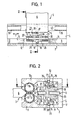
- 1 and 2 show two bodies 2 and 3 which can be displaced linearly relative to one another in the direction of the double arrow F, the first of which is of a long, essentially U-shaped hollow profile 4 which extends in the direction of the double arrow F and the other of which is perpendicular to the longitudinal direction of the hollow profile 4 extending and with its free end 5 protruding into the interior of the hollow profile arm 6 is formed, which carries at this free end 5 a scanning device 8, which serves to scan a marker carrier designed in the form of a linear scale 9, which is extends essentially over the entire length of the hollow profile 4 and is attached to the profile rear wall 12 connecting the two profile legs 10, 11 so that it protrudes from it towards the arm 6 carrying the scanning device 8.
- On the Linear scale 9 has a plurality of markings 14 spaced apart in the direction of the linear movement, with the aid of which the distance of a measuring standard 16 moving with the arm 6 from a zero point of the linear displacement (not shown in the figures) or the length of the body 3 at one Linear movement covered distance is to be measured.
- the hollow profile 4 can be connected to an elongated machine frame, while the arm 6 is rigidly connected to a machine slide that can be displaced along the machine frame.
- the markings 14 each have the shape of a narrow, elongated strip which is essentially perpendicular to the direction of the linear movement and which differs in terms of light transmission from the areas of the linear marking carrier 9 surrounding it.
- markings 14 can thus be scanned with the aid of a sensor 18 of the scanning device 8, in the present case designed as a differential photodiode, which, as can be seen in particular from FIG. 2, is mounted in one leg of a sensor carrier 19 encompassing the linear scale 9 in a fork-like manner. while a light source 20 is arranged in the opposite leg of the sensor carrier so that the connecting line between the light source 20 and the sensor 18 is approximately perpendicular to the surface of the linear marker carrier 9 bearing the markings 14.
- the sensor carrier 19 is fixedly connected to the central part of two straight rods 23, 24 arranged one above the other in FIG. 2, the free ends of which are via slide bearings of the two Legs 25, 26 of a bearing block 27, which is essentially U- shaped in the plan view of FIG. 1, are supported such that the two rods 23, 24 extend parallel to the direction of the linear movement.
- the two legs 25,26 of the probe carrier 19 which surround the fork-like end of the bearing block 27 rigidly mounted at the front end 5 of the arm 6 are spaced so far apart that the probe carrier 19 between them an oscillating movement due to the sliding mounting of the rods 23, 24 supporting it Can perform the direction of the linear displacement.
- This oscillation movement is generated in that an electromagnetic coil 29, 30 is arranged on the sides of the legs 25, 26 of the bearing block 27 facing away from the sensor carrier 19 such that the upper rod 23, consisting of a ferromagnetic material, has the free ends as the core in protrudes these two coils and can thus be moved back and forth in the direction of arrow F by controlling these two coils 29, 30 with a corresponding electrical signal.
- the electrical connections serving to control the coils 29, 30 are neither shown in the figures, nor are the wires leading to the light source 20 and the sensor 18.
- the light beam going from the light source 20 to the sensor 18 sweeps over, even when there is no relative movement between the two bodies 2, 3, light-impermeable markings 14 and translucent marking spaces, thereby changing it is modulated.
- the lower rod 24 only serves to guide the oscillating element 22 formed from the sensor carrier 19 and the upper rod 23.
- it could also consist of a ferromagnetic material and immerse at least with one of its free ends as a core in a further electromagnetic coil, which would then emit an electrical signal reflecting the actual oscillation movement of the oscillating element 22, the evaluation of which could be used, for example, to determine the effective mean oscillation speed v of a predetermined section of each oscillation stroke.
- the bearing block 27 In his between the front end 5 of the arm 6 and the M eß complicatlerthe 19 area lying, the bearing block 27 has a horizontal in Fig. 2, extending in the direction of the linear movement slot 32 in which a extending parallel to the first marker support 9, fixed is mounted on the sensor carrier 19 and co-oscillates with the second marker carrier 35.
- This second marking carrier 35 which is designed as a small plate, has, as will be explained in more detail below, some markings 45 to 49 which differ from the regions of the second marking carrier 35 which surround them, which markers are perpendicular to the direction of the oscillation movement and thus to the direction of the linear displacement extending narrow lines are formed.
- markings 45 to 49 are scanned by a second sensor 36, also formed by a differential photodiode, which is mounted in the bearing block 27 below the slot 32 such that the connecting line between it and a light source 37 arranged in the bearing block 27 above the slot 32 in is approximately perpendicular to the surface of the second marking carrier 35 bearing the markings 45 to 49.
- translucent markings 45 to 49 and opaque marking gaps run through the measuring light beam from the second measuring sensor 36 and its light in constant alternation Source 37 formed, firmly connected to the body 3 through the second scanner, whereby this light beam is also modulated.
- Light-emitting diodes which can either be LEDs or laser diodes, are preferably used as light sources 20 and 37.
- a hose 39 or 40 Attached to the end regions of the legs 10, 11 of the hollow profile 4 facing the arm 6 is a hose 39 or 40, which can be filled with a pressurized fluid and extends over the entire length of the hollow profile 4, on the inside facing the opposite leg at its ends, which are not shown in FIG. 1, but are located on the left or right in the top view there, on sealingly arranged end faces which cover the cross section of the hollow profile.
- the cross-sectional dimensions of the hoses 39, 40 are dimensioned such that, when filled, they touch along the surface 41 in the areas lying next to the arm 6 and thus seal the interior of the hollow profile 4 in an airtight and dustproof manner.
- the arm 6 is provided with wedge-shaped surfaces represented by dotted lines in FIG. 1, which form without sharp edges in the upper or lower one in FIG. 2 Pass over the surface of the arm 6, on which the left or right side edge of the arm 3 in FIG. 1 has its smallest thickness and rise towards the center of the arm 3 up to its maximum thickness.
- the hoses 39, 40 in the area in which the arm 6 passes between them are pressed apart and deformed in the manner shown in FIG. 2.
- the hoses are 39.40 so on the wedge surfaces of the arm 6 that the interior of the hollow section 4 remains completely sealed, although the arm 6 is freely movable in the direction of arrow F over the entire length of the hollow section 4.
- the upper hose 39 shown in section, is interrupted in the area of the arm 6, so that only the lower, not cut hose 40 is visible here.
- the two legs 25, 26 of the bearing block 27 are each connected to one another at their upper and lower ends by a connecting web 70 and 71 (see in particular FIG. 2) extending in the direction of the linear movement.
- a V-shaped groove 76, 79 extending in the direction of the linear movement is formed and arranged so that in FIG. 2 the connecting line of the two grooves coincides with the connecting line of the centers of the two rods 23, 24.
- the two grooves 76, 79 each serve to receive a plurality of balls, of which only one in FIG. 2, namely the upper ball 74 and the lower ball 75, and to hold them so that these balls move linearly the arm 6 in the direction of arrow F are taken from the bearing block 27.
- the apex angles of the grooves 77, 78 in the hollow profile 4 are substantially obtuse than the apex angles of the grooves 76, 79 in the bearing block 27. It is thereby achieved that the slippage of the balls 74, 75 which necessarily occurs in this arrangement occurs in the grooves 76, 79 of the bearing block 27, while a perfect rolling of the balls 74, 75 is ensured in the grooves 77, 78 of the hollow profile 4. As a result, an extremely exact and smooth guidance of the bearing block projecting freely from the body 2 with respect to the hollow profile 4 fastened to the other body 3 is advantageously achieved.
- an inventive device for measuring angular displacements has the main difference that instead of the linear scale 9, a circular dial is scanned, which is concentric on one of the two bodies is mounted to the axis of rotation of the relative movement.
- the other of the two bodies then carries the scanning device, which can be constructed in the same way as the scanning device 8 described above, and which is arranged such that the measuring standard 16 defined by the measurement line of gravity of the second sensor intersects the axis of rotation of the relative movement as a radial beam.
- the straight line distances measured between the markings of the scale disc and the measurement standards during a linear oscillating movement of the vibration system must advantageously be converted to arc distances, the above described scanning device are modified so that the first sensor moves back and forth on a partial circular path, the center of which lies in the axis of rotation of the relative movement. Since there are no linear displacements between the fixed marker carrier and its scanning device, the entire arrangement can be done without white teres are housed in a closed housing and shielded against environmental influences, the housing can have very small dimensions due to the use of only one dial and the small size of the oscillating scanning device.
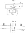
- the body 3 is positioned with respect to the body 2 such that the measurement standard 16, which is defined by the separating web of the differential photodiode fastened to the body 3 as a second sensor 36, is at a distance d from the marking 14 n + 1 .
- the vibration system of which only the oscillating sensor 18 and the second marking carrier 35 connected to it are shown in a highly schematic manner in FIG. 3. For the sake of clarity, the bearing and drive devices for the vibration system are omitted here.
- the measuring heavy line 42 of the oscillating sensor 18 defines the center of the oscillating system consisting of this sensor 18 and the second marking carrier 35. -
- the vibration system is symmetrical with respect to its geometric extension to this center.
- the second marking carrier 35 there is a first marking 45 lying on the measuring line of gravity of the oscillating sensor 18, which is used whenever its optical center passes over the measuring line of gravity of the fixed sensor 36 due to the oscillating movement of the oscillating system, which is the case here Case to generate the reference signal characterizing the zero deflection of the oscillating system.
- two further markings 46 and 47 are arranged to the left and right of the first marking 45 used to generate the reference signal, each of which has the distance s o / 2 from the first marking 45, so that the total distance between the two markings 46, 47 is equal to s o .
- This distance is measured very precisely at least once by any known method, for example interferometrically, with the aid of a measuring microscope or advantageously using the device described in DE-OS 30 18 528.
- a whole circular dial which has a large number of markings, is first precisely measured and then divided into individual pieces, each of which bears the markings required for carrying out the method according to the invention, the spacing of which is thus very precisely known.
- This distance is chosen so that with a given maximum amplitude of the sinusoidal Oszillationsschwingung the Oszillationsgeschwindi g- speed in the period of time with very good approximation, can be considered constant, the front at each oscillation stroke between the sweeping over the Meßhisline of the fixed probe 36 through the, in this lifting movement of the two marks 46, 47 and the sweeping of this measurement line through the rear of the two marks 46, 47 passes.
- the marking carrier 35 has two markings 48, 49 arranged in the vicinity of the left and right edges, respectively, which are arranged such that they only pass over the center of gravity of the fixed sensor 36 shortly before and after the oscillation system has passed through its reversal point, when the vibration system has experienced the minimum-maximum deflection, which guarantees the constancy of the oscillation speed during the period defined above.
- the two markings 48, 49 can be arranged somewhat asymmetrically to the center of the marking carrier 35, so that the double signal which is generated by one marking 48 when passing through the reversal point assigned to it is at a different distance from that from the other marking 49 double signal generated when passing through the other reversal point. The direction of the subsequent oscillation movement can then be concluded from these time differences.
- Fig. 4 in a time diagram in the first line, the signals of the fixed sensor 36 and in the second line, the signals of the oscillating sensor 18 are plotted, which result in the situation shown in Fig. 3 when the vibration system from the in Fig. 3 position continues swinging to the right to the reversal point there.
- the dashed line 51 in FIG. 4 corresponds approximately to the point in time, as it were in FIG. 3, as it were by a snapshot.
- the two signals 53, 54 are shown, which were generated by the fixed measuring sensor 36 or its downstream transmitter when passing through the preceding reversal point of the oscillating system due to the passing of the marking 49.
- the oscillating sensor 18 passes over the marking 14n, which is represented in the second line by the corresponding pulse 55. After the signal 57, the oscillating sensor 18 sweeps over the marking 14 n + 1 of the fixed marking carrier 9, as a result of which the sensor signal 60 shown in the second line of FIG. 4 is generated.
- the time interval A t between the reference signal 57 and the sensor signal 60 and on the other hand the time interval t between the two pulse-shaped signals 56 and 58 are measured. From these measured values and the known geometric distance s of the markings 46, 47 assigned to the signals 56, 58, the desired distance d is then obtained in accordance with the equation (3) explained above.
- two further pulse-shaped signals 62, 63 are shown on the far right, which are emitted by the sensor 36 when the marking 48 passes shortly before and shortly after the vibration system has passed through the second reversal point.
- the time interval between the two pulse-shaped signals 62, 63 is smaller than the corresponding time interval between the two pulse-shaped signals 53 and 54, which is due to the fact that the associated markings 49 and 48 differ. have left distances from the marking 45 located in the middle of the vibration system.
- the time intervals between the signals 53, 54 on the one hand and the signals 62, 63 on the other hand must not be less than a certain minimum value in order to ensure that the oscillation system really oscillates with a maximum amplitude which ensures the constancy of v o in the period t 0 .
- this further embodiment corresponds in function and structure completely to the embodiment described with reference to the figures.
- the schematic representation of FIG. 3 clearly shows that the device according to the invention can also be used without difficulty for measuring arc lengths or angles.
- the point at which the axis of rotation perpendicular to the plane of the drawing, about which the two bodies 2 and 3 move relative to one another, could be either above or below.
- the first marking carrier 9 are designed as a full circular disk around which the scanning device 8 rotates on the outside.
- the first marking carrier 9 would be a disk-shaped circular ring, the inner edge of which is encompassed by the sensor carrier.
Landscapes
- Physics & Mathematics (AREA)
- General Physics & Mathematics (AREA)
- Length Measuring Devices With Unspecified Measuring Means (AREA)
- Measurement Of Length, Angles, Or The Like Using Electric Or Magnetic Means (AREA)
- Length Measuring Devices By Optical Means (AREA)
- A Measuring Device Byusing Mechanical Method (AREA)
- Length-Measuring Instruments Using Mechanical Means (AREA)
Priority Applications (1)
| Application Number | Priority Date | Filing Date | Title |
|---|---|---|---|
| AT82111940T ATE33187T1 (de) | 1981-12-29 | 1982-12-23 | Verfahren und vorrichtung zur messung der laenge einer strecke oder eines bogens. |
Applications Claiming Priority (2)
| Application Number | Priority Date | Filing Date | Title |
|---|---|---|---|
| DE3151798A DE3151798C2 (de) | 1981-12-29 | 1981-12-29 | Verfahren und Vorrichtung zur Messung der Länge einer Strecke oder eines Bogens |
| DE3151798 | 1981-12-29 |
Publications (3)
| Publication Number | Publication Date |
|---|---|
| EP0083082A2 true EP0083082A2 (fr) | 1983-07-06 |
| EP0083082A3 EP0083082A3 (en) | 1986-01-22 |
| EP0083082B1 EP0083082B1 (fr) | 1988-03-23 |
Family
ID=6149953
Family Applications (1)
| Application Number | Title | Priority Date | Filing Date |
|---|---|---|---|
| EP82111940A Expired EP0083082B1 (fr) | 1981-12-29 | 1982-12-23 | Procédé et dispositif pour mesurer la longueur d'une droite ou d'une courbe |
Country Status (5)
| Country | Link |
|---|---|
| US (1) | US4550504A (fr) |
| EP (1) | EP0083082B1 (fr) |
| JP (1) | JPS58118905A (fr) |
| AT (1) | ATE33187T1 (fr) |
| DE (1) | DE3151798C2 (fr) |
Cited By (1)
| Publication number | Priority date | Publication date | Assignee | Title |
|---|---|---|---|---|
| CN112284308A (zh) * | 2019-07-24 | 2021-01-29 | 中国石油天然气股份有限公司 | 电磁超声横波测厚探头 |
Families Citing this family (7)
| Publication number | Priority date | Publication date | Assignee | Title |
|---|---|---|---|---|
| DE3410944C1 (de) * | 1984-03-24 | 1985-05-09 | Dr. Johannes Heidenhain Gmbh, 8225 Traunreut | Gekapselte Meßeinrichtung |
| DE3608884A1 (de) * | 1986-03-17 | 1987-09-24 | Mitec Moderne Ind Gmbh | Messanordnung |
| US5317650A (en) * | 1991-07-29 | 1994-05-31 | Xerox Corporation | Determination of the arc length of a curve |
| DE19718831A1 (de) * | 1997-05-05 | 1998-11-12 | Claas Usines France | Vorrichtung und Verfahren zur Regelung der Ballenlänge in einer Großballenpresse |
| US20050159917A1 (en) * | 2004-01-20 | 2005-07-21 | Borgwarner Inc. | Part length measurement technique using two or three proximity sensors |
| ATE534017T1 (de) * | 2010-02-09 | 2011-12-15 | Sick Stegmann Gmbh | Messvorrichtung zur absolutwertbestimmung von längen oder winkeln mit aus einzelnen teilstücken zusammengesetzter aktiver massverkörperung |
| JP5629742B2 (ja) * | 2012-09-28 | 2014-11-26 | 京セラドキュメントソリューションズ株式会社 | 電子機器及び画像形成装置 |
Family Cites Families (9)
| Publication number | Priority date | Publication date | Assignee | Title |
|---|---|---|---|---|
| DE1238225B (de) * | 1958-11-19 | 1967-04-06 | Hensoldt & Soehne Optik | Einrichtung zur selbsttaetigen Anzeige von Massstabeinstellungen an Maschinen |
| FR1480310A (fr) * | 1966-03-29 | 1967-05-12 | Sfena | Dispositif de sensibilisation et d'amortissement |
| US3582769A (en) * | 1970-02-24 | 1971-06-01 | Philips Corp | Device for the noncontact gauging the displacement of objects moved in a straight line |
| DE2730715C2 (de) * | 1974-07-26 | 1991-08-29 | Heinz 5121 Ostermiething Rieder | Einrichtung zur Längenmessung |
| SE409243B (sv) * | 1978-01-30 | 1979-08-06 | Westerberg Gerhard | Klave for metning av tredstammars diameter |
| DE3018527A1 (de) * | 1980-05-14 | 1981-11-19 | Walter Dipl.-Ing. Dr.-Ing. 8012 Ottobrunn Mehnert | Verfahren und vorrichtung zur messung einer laenge |
| DE3018496A1 (de) * | 1980-05-14 | 1981-11-19 | Walter Dipl.-Ing. Dr.-Ing. 8012 Ottobrunn Mehnert | Verfahren und vorrichtung zur messung eines winkels |
| DE3018528C2 (de) * | 1980-05-14 | 1986-06-05 | MTC, Meßtechnik und Optoelektronik AG, Neuenburg/Neuchâtel | Verfahren und Vorrichtung zur Messung der Winkelgeschwindigkeit eines rotierenden Körpers |
| DE3037810C2 (de) * | 1980-10-07 | 1982-11-04 | Dr. Johannes Heidenhain Gmbh, 8225 Traunreut | Inkrementale Längen- oder Winkelmeßeinrichtung |
-
1981
- 1981-12-29 DE DE3151798A patent/DE3151798C2/de not_active Expired
-
1982
- 1982-12-22 US US06/452,376 patent/US4550504A/en not_active Expired - Fee Related
- 1982-12-23 AT AT82111940T patent/ATE33187T1/de not_active IP Right Cessation
- 1982-12-23 EP EP82111940A patent/EP0083082B1/fr not_active Expired
- 1982-12-29 JP JP57234938A patent/JPS58118905A/ja active Pending
Cited By (2)
| Publication number | Priority date | Publication date | Assignee | Title |
|---|---|---|---|---|
| CN112284308A (zh) * | 2019-07-24 | 2021-01-29 | 中国石油天然气股份有限公司 | 电磁超声横波测厚探头 |
| CN112284308B (zh) * | 2019-07-24 | 2023-04-07 | 中国石油天然气股份有限公司 | 电磁超声横波测厚探头 |
Also Published As
| Publication number | Publication date |
|---|---|
| US4550504A (en) | 1985-11-05 |
| DE3151798A1 (de) | 1983-07-07 |
| DE3151798C2 (de) | 1985-12-12 |
| JPS58118905A (ja) | 1983-07-15 |
| EP0083082B1 (fr) | 1988-03-23 |
| ATE33187T1 (de) | 1988-04-15 |
| EP0083082A3 (en) | 1986-01-22 |
Similar Documents
| Publication | Publication Date | Title |
|---|---|---|
| DE102004015785B4 (de) | Verfahren zur Bestimmung der Abmessung eines Querschnitts eines Flachkabels oder eines Sektorleiters | |
| DE2248194B2 (de) | Mehrkoordinatenmaschine, insbesondere laengenmessmaschine | |
| DE2730715C2 (de) | Einrichtung zur Längenmessung | |
| DE2521618B1 (de) | Vorrichtung zum Messen oder Einstellen von zweidimensionalen Lagekoordinaten | |
| EP0242407A2 (fr) | Dispositif pour la mesure de petites longueurs | |
| DE2229887B2 (de) | Entfernungsmeßgerät mit einem als Sender arbeitenden Laser und seine Anwendung zur Geschwindigkeitsmessung | |
| DE1930111C3 (de) | Optische Vorrichtung zum Messen der Bewegung von gegeneinander bewegten Teilen | |
| EP0379097A2 (fr) | Procédé pour déterminer la position d'un bord et capteur photoélectrique pour cette détermination | |
| DE69601014T2 (de) | Lichtabtaster | |
| DE2054285A1 (de) | Vorrichtung zur Prazisionsmessung von Abmessungen von Prüflingen | |
| DE3542514C2 (fr) | ||
| EP0083082B1 (fr) | Procédé et dispositif pour mesurer la longueur d'une droite ou d'une courbe | |
| EP1995566A2 (fr) | Echelle pour un dispositif de mesure de position et dispositif de mesure de position | |
| EP2126517A1 (fr) | Capteur de déplacement incrémentiel inductif, procédé de détermination du décalage d'un premier objet par rapport à un deuxième objet et unité de détection inductive | |
| DE1548292B2 (de) | Meßvorrichtung zur berührungslosen Breitenmessung eines durchlaufenden Bandes | |
| DE2315471A1 (de) | Stellungsgeber fuer elektrische nachfuehreinrichtungen bei registriersystemen | |
| WO2003031993A1 (fr) | Appareil de mesure encapsule | |
| EP0437597B1 (fr) | Dispositif pour la mesure de longueurs, d'angles et similaire | |
| DE4111873C2 (de) | Meßeinrichtung an einer Werkzeugmaschine zum Bestimmen des jeweiligen Standorts eines beweglichen Bauteils | |
| DE3608884C2 (fr) | ||
| DE3608384C2 (fr) | ||
| DE19813803C1 (de) | Meßanordnung zur Messung von Längen und Abständen | |
| DE3510937A1 (de) | Laserstrahlmessvorrichtung fuer hochleistungslaser | |
| DE102006025045B4 (de) | Verfahren zum Betrieb einer optoelektronischen Vorrichtung | |
| EP4545911A1 (fr) | Entraînement à codage absolu magnétique |
Legal Events
| Date | Code | Title | Description |
|---|---|---|---|
| PUAI | Public reference made under article 153(3) epc to a published international application that has entered the european phase |
Free format text: ORIGINAL CODE: 0009012 |
|
| AK | Designated contracting states |
Designated state(s): AT CH FR GB LI NL SE |
|
| 17P | Request for examination filed |
Effective date: 19831229 |
|
| RAP1 | Party data changed (applicant data changed or rights of an application transferred) |
Owner name: MTC MESSTECHNIK UND OPTOELEKTRONIK AG |
|
| PUAL | Search report despatched |
Free format text: ORIGINAL CODE: 0009013 |
|
| AK | Designated contracting states |
Designated state(s): AT CH FR GB LI NL SE |
|
| 17Q | First examination report despatched |
Effective date: 19870522 |
|
| GRAA | (expected) grant |
Free format text: ORIGINAL CODE: 0009210 |
|
| RIN1 | Information on inventor provided before grant (corrected) |
Inventor name: MEHNERT, WALTER, DR. |
|
| RIN1 | Information on inventor provided before grant (corrected) |
Inventor name: MEHNERT, WALTER, DR. |
|
| AK | Designated contracting states |
Kind code of ref document: B1 Designated state(s): AT CH FR GB LI NL SE |
|
| REF | Corresponds to: |
Ref document number: 33187 Country of ref document: AT Date of ref document: 19880415 Kind code of ref document: T |
|
| REG | Reference to a national code |
Ref country code: CH Ref legal event code: PLI Owner name: MITEC MODERNE INDUSTRIETECHNIK GMBH |
|
| ET | Fr: translation filed | ||
| GBV | Gb: ep patent (uk) treated as always having been void in accordance with gb section 77(7)/1977 [no translation filed] | ||
| REG | Reference to a national code |
Ref country code: CH Ref legal event code: PLIA Free format text: MITEC MODERNE INDUSTRIETECHNIK GMBH |
|
| PG25 | Lapsed in a contracting state [announced via postgrant information from national office to epo] |
Ref country code: GB Free format text: LAPSE BECAUSE OF NON-PAYMENT OF DUE FEES Effective date: 19881122 |
|
| PGFP | Annual fee paid to national office [announced via postgrant information from national office to epo] |
Ref country code: FR Payment date: 19881209 Year of fee payment: 7 |
|
| PLBE | No opposition filed within time limit |
Free format text: ORIGINAL CODE: 0009261 |
|
| STAA | Information on the status of an ep patent application or granted ep patent |
Free format text: STATUS: NO OPPOSITION FILED WITHIN TIME LIMIT |
|
| 26N | No opposition filed | ||
| REG | Reference to a national code |
Ref country code: CH Ref legal event code: PFA Free format text: MITEC MIKROELEKTRONIK MIKROTECHNIK INFORMATIK GMBH |
|
| REG | Reference to a national code |
Ref country code: FR Ref legal event code: TP |
|
| NLS | Nl: assignments of ep-patents |
Owner name: MITEC MIKROELEKTRONIK MIKROTECHNIK INFORMATIK GMBH |
|
| PG25 | Lapsed in a contracting state [announced via postgrant information from national office to epo] |
Ref country code: AT Effective date: 19891223 |
|
| PG25 | Lapsed in a contracting state [announced via postgrant information from national office to epo] |
Ref country code: SE Effective date: 19891224 |
|
| PG25 | Lapsed in a contracting state [announced via postgrant information from national office to epo] |
Ref country code: LI Effective date: 19891231 Ref country code: CH Effective date: 19891231 |
|
| NLS | Nl: assignments of ep-patents |
Owner name: MITEC MIKROELEKTRONIK MIKROTECHNIK INFORMATIK GMBH |
|
| PG25 | Lapsed in a contracting state [announced via postgrant information from national office to epo] |
Ref country code: NL Effective date: 19900701 |
|
| NLV4 | Nl: lapsed or anulled due to non-payment of the annual fee | ||
| PG25 | Lapsed in a contracting state [announced via postgrant information from national office to epo] |
Ref country code: FR Effective date: 19900831 |
|
| REG | Reference to a national code |
Ref country code: CH Ref legal event code: PL |
|
| REG | Reference to a national code |
Ref country code: FR Ref legal event code: ST |
|
| EUG | Se: european patent has lapsed |
Ref document number: 82111940.1 Effective date: 19900829 |