EP0083092A2 - Blindage isolant pour une installation de commutation et de répartition moyenne tension - Google Patents
Blindage isolant pour une installation de commutation et de répartition moyenne tension Download PDFInfo
- Publication number
- EP0083092A2 EP0083092A2 EP82111982A EP82111982A EP0083092A2 EP 0083092 A2 EP0083092 A2 EP 0083092A2 EP 82111982 A EP82111982 A EP 82111982A EP 82111982 A EP82111982 A EP 82111982A EP 0083092 A2 EP0083092 A2 EP 0083092A2
- Authority
- EP
- European Patent Office
- Prior art keywords
- parts
- encapsulation
- insulating material
- insulating
- sheet metal
- Prior art date
- Legal status (The legal status is an assumption and is not a legal conclusion. Google has not performed a legal analysis and makes no representation as to the accuracy of the status listed.)
- Granted
Links
Images




Classifications
-
- H—ELECTRICITY
- H02—GENERATION; CONVERSION OR DISTRIBUTION OF ELECTRIC POWER
- H02B—BOARDS, SUBSTATIONS OR SWITCHING ARRANGEMENTS FOR THE SUPPLY OR DISTRIBUTION OF ELECTRIC POWER
- H02B13/00—Arrangement of switchgear in which switches are enclosed in, or structurally associated with, a casing, e.g. cubicle
- H02B13/02—Arrangement of switchgear in which switches are enclosed in, or structurally associated with, a casing, e.g. cubicle with metal casing
- H02B13/035—Gas-insulated switchgear
- H02B13/045—Details of casing, e.g. gas tightness
-
- H—ELECTRICITY
- H02—GENERATION; CONVERSION OR DISTRIBUTION OF ELECTRIC POWER
- H02B—BOARDS, SUBSTATIONS OR SWITCHING ARRANGEMENTS FOR THE SUPPLY OR DISTRIBUTION OF ELECTRIC POWER
- H02B13/00—Arrangement of switchgear in which switches are enclosed in, or structurally associated with, a casing, e.g. cubicle
- H02B13/01—Arrangement of switchgear in which switches are enclosed in, or structurally associated with, a casing, e.g. cubicle with resin casing
Definitions
- the invention relates to system parts of an electrical medium-voltage switchgear and distribution system surrounding insulating material encapsulation, which is composed of several pressure-tightly joined together, preferably filled with an insulating gas insulating material parts.
- the object of the present invention is to eliminate the difficulties and disadvantages described, ie So to create a gas-tight and diffusion-resistant encapsulation for system parts of electrical medium-voltage switchgear and distribution systems, which is worthy of being priced, but is technically and qualitatively convincingly able to withstand the mechanical and electrical loads to be expected, mon. is day-friendly and low-maintenance, offers space and weight savings and is characterized by an insensitivity to the risk of so-called arcing at the occurrence of arcing faults.
- an advantageous embodiment of the concept of the invention can be seen in the proposal to join two identical or mutually mirror-image half-shell shaped sheet metal parts to form the additional metal encapsulation for individual areas of the insulating encapsulation, to connect them gas-tight to one another and in this way to obtain encapsulation elements which are very different Have figurations, can be selected for the respective need and can be put together in building blocks; the characterizing parts of claims 2, 3 and 4 show all essential figurations or configurations. Parts and groups of parts of this type can be prefabricated in terms of their colors and in some cases also pre-assembled and, as already mentioned above, can now be assembled in a modular manner at the installation site of the system. For this, it is with pleasure even expedient, each a separate insulating material zusharm - assign Liehe metal enclosure.
- the insulating material parts of the insulating material encapsulation and the sheet metal molded parts surrounding these parts are connected to one another at least in some areas in the manner of a composite material. This can be done for example by gluing or by other sealing processes.
- a special proposal for further development in this direction provides for the insulation parts of the insulation encapsulation to be formed by foaming the individual sheet metal parts or a previously gas-tight group of two or more sheet metal parts with a hard structural foam, for example by molding foam with rigid polyurethane integral foam.
- the insulating parts by powder coating, spray coating, dip resin coating or cast resin coating of the sides of the individual sheet metal parts facing the encapsulation interior or by such treatment of the interior of a previously gas-tight group of two or more sheet metal parts; the coating thickness of sheet metal parts to be treated in this way is preferably 1.5 to 5 mm.
- the step-like or flute-like recesses of abutting insulating material parts are dimensionally coordinated with one another in such a way that, together with the mutually directed edge edges of the molded sheet metal parts, they form a circumferential, at least almost closed channel, in which a sealing element shared by two insulating material parts can be inserted, which in turn is shaped and dimensioned in its cross-section so that it presses in the assembled position of the insulating encapsulation sealingly against the edges of both adjacent sheet metal parts near the edge.
- Another expedient development is to be seen in equipping the insulating material parts on their opening edges to be attached to an adjacent insulating material part with cams and / or recessed recesses projecting perpendicular to the opening plane, which are dimensioned and located such that the cams of one of the insulating material are in the assembled position of the insulating material parts parts penetrate into corresponding recesses of the adjacent insulating material part and thus form an anti-rotation device between the two insulating material parts.
- a larger number of cams or recesses can be regularly distributed over the circumference of the partial circles running through the centers of the cams or recesses (an approximately round cross section of the insulating material parts is assumed here), for example at angular intervals of 5 or 10 or 30 degrees. In this way, a large selection of different angular positions of the individual insulating parts relative to one another is offered.
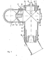
- FIG. 1 illustrates a comparatively small area of an encapsulation of insulating material, the interior of which, in the operating state, is filled with a special insulating gas, for example with sulfur hexafluoride (SF 6 ), with a slight excess pressure compared to the atmospheric pressure.
- a special insulating gas for example with sulfur hexafluoride (SF 6 )
- SF 6 sulfur hexafluoride
- FIG. 1 illustrates how this can look, for example.
- a cross-sectionally shaped insulating material part 11 with a total of four opening sockets 12, 13, 14 and 15 can be seen here.
- the opening socket 12 is by means of a flange part 16, which incidentally is gas and pressure tight contains introduced lens 17 made of bulletproof glass or the like, closed.
- this layer disk 17 offers the possibility of an insight into the interior of the insulating material part 11, for example in order to be able to inspect the position and condition of certain moving or wearing parts without opening the encapsulation.
- the opening connector 13 on the insulating part 11 borders on a switch receiving connector 18, which serves to receive and mount a circuit breaker and has a shape specially adapted to this holder of the switch.
- this switch receptacle connector 18 is bordered by a cable connector 19 which, in contrast to the other encapsulation elements, remains unlocked at its connector end opposite the connector 18, i.e. his inside is with the. free atmosphere connected.
- a specially designed bearing socket 20 for receiving and mounting a disconnector drive is flanged to the opening socket 14 of the insulating part 11.
- the special configuration of an implementation point for a movable drive member (indicated at both ends as broken off) will be discussed in connection with the explanations relating to FIGS. 4 and 10.
- the bearing socket 20 is in turn connected to an angular, T-shaped or also cruciform encapsulation element (depending on the present case), namely a flanged-on insulating material part 22, which in turn borders on a tubular encapsulation element 23 which serves to receive a current busbar.
- opening stub 15 receives a cover flange part 24, which is provided with bushings for actuators 25 and 26 (also indicated as broken off).
- FIG. 2 illustrates - on an enlarged scale compared to FIG. 1 - once again the insulating part 11 with its opening sockets 12, 13, 14 and -15.
- the complete insulating material part 11 is composed of correspondingly drawn sheet metal parts in half-shell form, of which only one, namely the sheet metal part 27, can be seen in the sectional view in FIG. 2, and this is indicated by an emphasized thick line along the outer edges of the cross-hatched plastic walls 28.
- Sheet metal parts (27) are provided with flat edges 29 on their mutually facing edges, which serve for the gas-tight assembly of the two sheet metal parts; More detailed explanations are given in connection with the description of the design options according to FIG. 7.
- these are foamed with the rigid foam already mentioned, as a result of which the actual insulating part is only formed.
- a correspondingly shaped insulating material part can also be produced separately and inserted between the sheet metal molded parts, which in this case are connected to one another in a gas-tight manner only after the insulating material part has been inserted.
- the insulating material part regardless of whether it has been produced by foaming or is obtained as a separate part, has special formations, which are explained in the explanations for FIGS. 8 and 9.
- Fig. 3 illustrates - also in an enlarged view compared to FIG. 1 - the already mentioned cover flange part 24 with the actuators 25 and 26, also already mentioned, shown broken-off.
- the cover flange part 24, like the previously described insulating material part 11, consists of polyurethane integral Rigid foam and has an additional metal encapsulation 30 on its wall directed towards the free atmosphere in the assembled position, which is also indicated here by a thicker stroke.
- This metal encapsulation 30 is flanged in the area of the outer flange wall 31 of the cover flange part 24 and abuts - in the assembled position - on or almost against the sheet metal part 27 of the cruciform insulating material part 11.
- the metal encapsulation 30 borders on metallic bearing and guide members 32 and 33 and is connected to them in a gastight manner, that is to say, for example, welded or soldered or instead glued or cemented in a pressure-tight manner.
- metallic bearing and guide member 32 is directly involved in the sealing measures for the actuating member 25, the bearing and guide member 33, on the other hand, serves only to support and guide the actuating member 26 and borders on a sealing point 34.
- the structure and mode of operation of these sealing points are to be explained with reference to FIG. 10, as has already been mentioned.
- FIG. 4 shows the bearing connector 20, which is also provided with an additional metal encapsulation 36 in the area in which it comes into contact with the free atmosphere in the mounted position.
- This metal encapsulation 36 is perforated for the passage of the previously mentioned movable drive member 21 and here adjoins a guide sleeve 37 in a gas-tight manner.
- the design of this sealing point, which is provided with the number 38, is basically the same as that in FIG. 10.
- FIG. 5 shows the switch receptacle 18 with the cable connector 19 flanged to it.
- This switch receptacle 18 is also provided with a metal encapsulation 39 in its circumferential area, but, as has already been stated, it does not consist of rigid integral polyurethane foam, but instead of a diffusion-resistant plastic, for example epoxy resin.
- a metallic ring 40 is also embedded in this material and is used to hold and precisely hold a circuit breaker.
- the cable connector 19 no longer serves directly for the encapsulation, but rather as a cover and protection against accidental contact for a cable connection point.
- it is double-layered, i.e. an outer cladding layer 41 consists of an impact-resistant plastic, while the inner layer 42 is formed by a foamed plastic.
- a plastic coating of a thin metal sheath on both sides can also be carried out by dipping into a dipping resin and thus the cable connector 19 is formed.
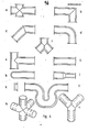
- insulating material parts provided with additional metal encapsulation are used to form an insulating material encapsulation, on the one hand those which have very specific additional shapes for, for example, carrying out moveable parts Parts or for the mounting of switches or their drives must contain, but on the other hand also insulating parts without special shapes are required, for example for encapsulating busbars or branch lines and the like.
- insulating parts without special shapes are required, for example for encapsulating busbars or branch lines and the like.
- Fig. 6 shows the possible basic forms, the representations being largely simplified. The individual representations are briefly listed below, and that shows the representation a: a cross piece, similar to that in FIG. 2,
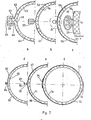
- half-shells 44 and 45 are provided with bevels 46 and 47 that face one another flat but are not adjacent to one another, between which a formation 48 on the insulating material part 43 is inserted in a certain surface area and a middle leg 49 of a clip 50 in the other surface area.
- a design is particularly recommended if the half-shells (44, 45) consist of magnetizable metal sheets. In this way a reduction in the magnetic conductivity is achieved, provided that the clip 50 also consists of a non-magnetizable material, but for example of a high-strength plastic.
- a sealing material (not shown in detail) in the form of a seal or an adhesive between the shape 48 on the insulating material part 43 and the adjacent folds 46 and 47 and the sides of the fold facing these Middle leg 49 of clip 50.
- the individual representation "b” illustrates a modification of the construction just described, namely here the (not numbered) folds of metal half-shells 51 and 52 lie practically directly on top of one another with the interposition of a thin (not shown) sealing material or sealing film; a clamp part 53 presses the mentioned folds of the half-shells 51 and 52 together gas-tight.
- a still different execution possibility illustrates the individual representation "c".
- this joint has been shown enlarged in a detail "A”.
- the mutually directed edge regions of the half-shells 55 and 56 have U-shaped flanges 57 and 58, between which an approximately H-shaped sealing element 59 is arranged in such a way that the flanges 57 and 58 fit into the nutar Insert the term recesses of the sealing element 59.
- a clamp part 60 the free ends of which lie in the formed grooves of the flanges 57 and 58, presses the edge regions of the half-shells 55 and 56 to one another and thus creates a sealed connection between the two half-shells.
- an insulating material part 61 enclosed by these half-shells 55 and 56 is subsequently produced by foaming; instead, a prefabricated insulating part could also be inserted before the half-shells 55 and 56 are joined together.
- a prefabricated insulating part could also be inserted before the half-shells 55 and 56 are joined together.
- either several individual clip parts (60) consisting of a spring band or a correspondingly dimensioned spring wire can be used, which are arranged next to one another at certain intervals, but instead a correspondingly slit piece of pipe can also be used as the clip part.
- the individual representation "d" in FIG. 7 shows a relatively simple embodiment, in which the mutually facing edges of half-shells 62 and 63 are flanged or bent out like a gutter and then soldered to one another, thereby forming a continuous, gas-tight soldering point 64.
- These half-shells 62 and 63 also enclose an insulating material body 65, which is already formed in the manner described.
- the one in the individual representation "e” is formed, namely here edges of half-shells 66 and 67 facing each other are folded so that they initially form tabs 68 and 69 lying flat against one another, which are then fused together by roll seam welding at the indicated welding point 70, that is to say are therefore welded to one another without filler material.
- These half-shells 66 and 67 also enclose an insulating material body 71 in the manner already described.
- the overlapped areas can now be soldered or welded together (e.g. welded with a roll seam) or finally glued together gas-tight.
- welding processes in the form of spot welds
- adhesive bonding is also conceivable.
- An insulating body 76 can also be foamed or inserted in a described manner in a closed metal encapsulation formed in this way.
- connection options shown for individual half-shells with one another merely represent exemplary embodiments which - of course with corresponding devices - can be implemented in a simple manner.
- other design options may also be expedient, for example those which are customary in the production of cans.
- FIGS. 8 and 9 show, on an enlarged scale, a cross section through a border of two abutting insulating material bodies 77 and 78, which, as can be seen, expand like a flange at their opening edges, ie they each have a circumferential collar 79 and 80, respectively.
- the metallic encapsulations 81 and 82 assigned to the insulating material parts 77 and 78 are adapted to this collar and surround them up to almost the joint 83.
- collars 79 and 80 have step-like recesses 84 and 85 on their mutually facing outer edges, which, together with the adjacent outer edge areas of the associated encapsulations 81 and 82, form insertion grooves which form an almost closed channel in the assembled position of two adjacent insulating material parts (77, 78) .
- a circumferential sealing element 86 is now arranged in this channel (illustrated) mounting position lies sealingly against the edges of the encapsulations 81 and 82, as well as against the walls of the step-like recesses 84 and 85.
- the cohesion of the insulating material parts 77 and 78 together with their metallic encapsulations 81 and 82 takes place by means of a two-part or multi-part clamping clamp 87 in an approximately U-shaped cross-sectional configuration, with legs 88 and 89 of the clamping clamp 87 in the course of the slopes of the collars 79 and 80 or adapt to the metallic encapsulations 81 and 82 adapted to it.
- the clamp 87 for example by means of screw elements which can be screwed into the indicated threaded bores 90 and 91
- the insulating parts 77 and 78 are pressed against one another as a result of the conicity and at the same time the sealing element 86 is pressed even more firmly against the aforementioned wall areas.
- Fig. 9 shows the same section as Fig. 8; the only essential difference is that here a sealing element 94 with an essentially rectangular cross section is used instead of one with a trapezoidal shape, as shown in FIG. 8.
- step-like recesses 95 and 96 in the indicated insulating material parts 97 and 98 are also adapted to this shape of the sealing element 94.
- the clamp 29 that can be seen in this illustration corresponds to that (87) in FIG. 8, but is shown in a cut position, whereas the representation in FIG. 8 shows an end region of such a clamp.
- FIG. 10 illustrates, on a larger scale than FIGS. 1 to 5 and 7, a passage point through an insulating material encapsulation 100 with additional metal encapsulation 101 for a movable member 102, for example an actuating member.
- This movable member 102 is rigidly and also gas-tightly connected to a guide piston 103.
- This guide piston 103 has circumferential, comparatively narrow grooves 104 and 105 at its longitudinal end regions, in contrast, in its central region, a wide groove 106 with a trapezoidal cross section. As can be seen from the illustration ; are housed in the narrow grooves 104 and 105 O-ring sealing elements 107 and 108, which are resistant to abrasion and at the same time are oil and grease resistant.
- the wide groove 106 which is trapezoidal in cross section is filled with a liquid sealant 109, for example with a viscous oil that is suitable for the special need or a special soft fat or gel.
- the guide piston 103 directly borders on the outer side of the insulating material encapsulation 100 on its side pointing to the right in the figure (it would also be conceivable to provide the insulating material encapsulation 100 at this point with a plastic lining in the form of a bushing or the like), in in its central region it penetrates the metal encapsulation 101 without, however, having to directly adjoin it, and in its left end region an inner cylindrical guide part 110 which is welded, soldered or otherwise connected to the metal encapsulation 101 in a gas-tight manner, for example glued gas-tight.
- the movable member 102 with the described and recognizable equipment in its lead-through area is now able to perform both a rotating and - at least to a certain extent - an axial movement without impairing the sealing of the gas atmosphere located inside the insulating material encapsulation 100.
- the liquid seal depot which is formed by the groove 106.
- the liquid sealant 109 contained therein effects the actual gas seal, whereas the O-ring elements 107 and 108 primarily serve to prevent the leakage of liquid sealant, especially in the event of axial movements of the movable member 102.
- the fat deposit serves primarily to seal the gas and electrical sealing "of the interior of the encapsulation to the outside. The fat deposit practically hides and isolates the inside edge of the metal enclosure 101.
- the bushings shown and named in FIG. 1 both for the movable drive member 21 and for the actuators 25 and 26 are all constructed according to the principle just described and shown in FIG. 10, albeit with dimensions adapted to the respective need.
Landscapes
- Engineering & Computer Science (AREA)
- Power Engineering (AREA)
- Insulating Bodies (AREA)
- Shielding Devices Or Components To Electric Or Magnetic Fields (AREA)
- Gas-Insulated Switchgears (AREA)
- Patch Boards (AREA)
- Thermal Insulation (AREA)
- High-Tension Arc-Extinguishing Switches Without Spraying Means (AREA)
Priority Applications (1)
| Application Number | Priority Date | Filing Date | Title |
|---|---|---|---|
| AT82111982T ATE42873T1 (de) | 1981-12-24 | 1982-12-23 | Kapselung einer elektrischen mittelspannungsschalt- und -verteileranlage. |
Applications Claiming Priority (2)
| Application Number | Priority Date | Filing Date | Title |
|---|---|---|---|
| DE3151406 | 1981-12-24 | ||
| DE19813151406 DE3151406A1 (de) | 1981-12-24 | 1981-12-24 | "isolierstoffkapselung fuer anlagenteile einer elektrischen mittelspannungsschalt- u. -verteileranlage" |
Publications (3)
| Publication Number | Publication Date |
|---|---|
| EP0083092A2 true EP0083092A2 (fr) | 1983-07-06 |
| EP0083092A3 EP0083092A3 (en) | 1986-01-02 |
| EP0083092B1 EP0083092B1 (fr) | 1989-05-03 |
Family
ID=6149742
Family Applications (1)
| Application Number | Title | Priority Date | Filing Date |
|---|---|---|---|
| EP82111982A Expired EP0083092B1 (fr) | 1981-12-24 | 1982-12-23 | Blindage isolant pour une installation de commutation et de répartition moyenne tension |
Country Status (3)
| Country | Link |
|---|---|
| EP (1) | EP0083092B1 (fr) |
| AT (1) | ATE42873T1 (fr) |
| DE (2) | DE3151406A1 (fr) |
Cited By (5)
| Publication number | Priority date | Publication date | Assignee | Title |
|---|---|---|---|---|
| EP0198181A1 (fr) * | 1985-04-17 | 1986-10-22 | BROWN, BOVERI & CIE Aktiengesellschaft | Eléments d'enveloppement servant à l'enveloppement étanche au gaz d'installations électriques et procédé de fabrication de leurs parties à rendre étanches |
| EP0624924A3 (fr) * | 1993-05-12 | 1996-05-15 | Showa Electric Wire & Cable Co | Connecteur conductif pour appareil de commutation. |
| EP2315326A1 (fr) * | 2009-10-22 | 2011-04-27 | ABB Technology AG | Ensemble conducteur à isolation gazeuse et procédé pour assembler un boîtier d'un ensemble conducteur à isolation gazeuse |
| WO2022017584A1 (fr) * | 2020-07-21 | 2022-01-27 | Hivoduct Ag | Conception de bride pour appareillage de commutation à isolation gazeuse haute tension (gis), barres omnibus et lignes (gil) |
| CN119909847A (zh) * | 2025-04-02 | 2025-05-02 | 江苏安靠智电股份有限公司 | 一种gil三支柱绝缘子用微粒捕捉装置的结构及其制造方法 |
Families Citing this family (8)
| Publication number | Priority date | Publication date | Assignee | Title |
|---|---|---|---|---|
| DE3347006A1 (de) * | 1983-12-24 | 1985-07-04 | Brown, Boveri & Cie Ag, 6800 Mannheim | Kapselung fuer anlagenteile einer elektrischen mittelspannungsschalt- und -verteileranlage |
| DE3409709A1 (de) * | 1984-03-16 | 1985-09-19 | Brown, Boveri & Cie Ag, 6800 Mannheim | Elektrische anlage |
| DE3513742A1 (de) * | 1985-04-17 | 1986-10-23 | Brown, Boveri & Cie Ag, 6800 Mannheim | Kolben-zylinder-anordnung, insbesondere fuer die betaetigung von innerhalb einer gasdichten kapselung gelegenen funktionselementen einer elektrischen mittelspannungsschalt- und -verteileranlage, sowie verfahren zur herstellung einer radialdichtungsstelle an der kolben-zylinder-anordnung |
| DE29806211U1 (de) * | 1998-03-27 | 1998-06-04 | Siemens AG, 80333 München | Kapselungsbaustein für eine Hochspannungsschaltanlage |
| DE102008019165A1 (de) * | 2008-04-17 | 2009-11-19 | Bimed Teknik A.S., Büyükcekmece | Kabelverschraubung, insbesondere für ein Abschirm- oder Erdungskabel |
| DE102008063683A1 (de) * | 2008-12-19 | 2010-07-08 | Abb Technology Ag | Gasisolierter Schalteer |
| AU2010312878B2 (en) * | 2009-10-29 | 2014-04-10 | Mitsubishi Electric Corporation | Power switching device |
| DE102013220179B4 (de) * | 2013-10-07 | 2015-06-25 | Siemens Aktiengesellschaft | Verfahren zur Herstellung von Behälterteilen für gekapselte Schaltanlagen und gekapselte Schaltanlage |
Family Cites Families (4)
| Publication number | Priority date | Publication date | Assignee | Title |
|---|---|---|---|---|
| FR1261840A (fr) * | 1960-07-07 | 1961-05-19 | Coq Nv | Perfectionnements apportés aux dispositifs blindés pour la distribution d'électricité |
| DE2804607A1 (de) * | 1978-02-03 | 1979-08-09 | Driescher Spezialfab Fritz | gekapselte, isoliergasgefuellte mittelspannungsschaltanlage |
| DE2824623A1 (de) * | 1978-06-05 | 1979-12-06 | Driescher Spezialfab Fritz | Fabrikfertige, gasisolierte mittelspannungsschaltanlage |
| DE3040350C2 (de) * | 1980-10-25 | 1985-06-05 | Brown, Boveri & Cie Ag, 6800 Mannheim | Kapselungselemente für Anlagenteile einer elektrischen Mittelspannungsschalt- und -verteileranlage |
-
1981
- 1981-12-24 DE DE19813151406 patent/DE3151406A1/de not_active Withdrawn
-
1982
- 1982-12-23 EP EP82111982A patent/EP0083092B1/fr not_active Expired
- 1982-12-23 AT AT82111982T patent/ATE42873T1/de active
- 1982-12-23 DE DE8282111982T patent/DE3279674D1/de not_active Expired
Cited By (9)
| Publication number | Priority date | Publication date | Assignee | Title |
|---|---|---|---|---|
| EP0198181A1 (fr) * | 1985-04-17 | 1986-10-22 | BROWN, BOVERI & CIE Aktiengesellschaft | Eléments d'enveloppement servant à l'enveloppement étanche au gaz d'installations électriques et procédé de fabrication de leurs parties à rendre étanches |
| EP0624924A3 (fr) * | 1993-05-12 | 1996-05-15 | Showa Electric Wire & Cable Co | Connecteur conductif pour appareil de commutation. |
| CN1051410C (zh) * | 1993-05-12 | 2000-04-12 | 株式会社东芝 | 开关用导电连接器 |
| EP2315326A1 (fr) * | 2009-10-22 | 2011-04-27 | ABB Technology AG | Ensemble conducteur à isolation gazeuse et procédé pour assembler un boîtier d'un ensemble conducteur à isolation gazeuse |
| WO2022017584A1 (fr) * | 2020-07-21 | 2022-01-27 | Hivoduct Ag | Conception de bride pour appareillage de commutation à isolation gazeuse haute tension (gis), barres omnibus et lignes (gil) |
| CN116368702A (zh) * | 2020-07-21 | 2023-06-30 | 希沃杜克公司 | 用于高压气体绝缘开关装置(gis)、母线和管线(gil)的法兰设计 |
| US12322934B2 (en) | 2020-07-21 | 2025-06-03 | Hivoduct Ag | Flange design for high-voltage gas-insulated switchgear (GIS), busbars and lines (GIL) |
| CN119909847A (zh) * | 2025-04-02 | 2025-05-02 | 江苏安靠智电股份有限公司 | 一种gil三支柱绝缘子用微粒捕捉装置的结构及其制造方法 |
| CN119909847B (zh) * | 2025-04-02 | 2026-01-30 | 江苏安靠智电股份有限公司 | 一种gil三支柱绝缘子用微粒捕捉装置的结构及其制造方法 |
Also Published As
| Publication number | Publication date |
|---|---|
| EP0083092A3 (en) | 1986-01-02 |
| DE3279674D1 (en) | 1989-06-08 |
| ATE42873T1 (de) | 1989-05-15 |
| DE3151406A1 (de) | 1983-07-07 |
| EP0083092B1 (fr) | 1989-05-03 |
Similar Documents
| Publication | Publication Date | Title |
|---|---|---|
| EP0083092B1 (fr) | Blindage isolant pour une installation de commutation et de répartition moyenne tension | |
| EP1038344A1 (fr) | Dispositif et procede permettant le maintien et le passage d'objets allonges | |
| DE1938706A1 (de) | Hochspannungsleitung | |
| DE3230091A1 (de) | Druckgasisolierter stromwandler | |
| EP0059255A1 (fr) | Installation de commutation électrique à moyenne tension, triphasée, à enveloppe métallique remplie de gaz | |
| DE7212043U (de) | Hochspannungsschalter | |
| EP0834208B1 (fr) | Coulage de barres omnibus a travers les parois adjacentes de deux panneaux de couplage adjacents | |
| DE102008033495B4 (de) | Sammelschienenkupplung für eine elektrische Schaltanlage | |
| DE3334682C2 (fr) | ||
| DE3040350C2 (de) | Kapselungselemente für Anlagenteile einer elektrischen Mittelspannungsschalt- und -verteileranlage | |
| DE3540547A1 (de) | Hochspannungsstromwandler und verfahren zur herstellung eines derartigen hochspannungsstromwandlers | |
| DE4444011C1 (de) | Anordnung zur Durchführung eines Kabels oder dergleichen durch eine Öffnung einer Wand | |
| DE19856025C2 (de) | Kompakte Übergangsmuffe | |
| EP0703593B1 (fr) | Colonne polaire pour un disjoncteur électrique | |
| DE3843943C2 (fr) | ||
| EP2258972A1 (fr) | Elément avec bride et son procédé de fabrication | |
| DE69210131T2 (de) | Anordnung zum Verbinden zweier Kabel für hohe oder sehr hohe Spannung | |
| DE19850693B4 (de) | Druckgasisolierte Schaltanlage | |
| DE3641573A1 (de) | Gehaeuse | |
| DE102006056656A1 (de) | Schaltermodul für eine elektrische Schaltanlage | |
| DE3347006A1 (de) | Kapselung fuer anlagenteile einer elektrischen mittelspannungsschalt- und -verteileranlage | |
| DE3224940C2 (fr) | ||
| DE3739120C2 (de) | Durchführungsanordnung für eine Betätigungsstange einer gekapselten Mittelspannungsschalt- oder -verteileranlage | |
| DE4035472C2 (de) | Schaltgerät | |
| DE2806480A1 (de) | Gekapselte mittelspannungsschaltanlage |
Legal Events
| Date | Code | Title | Description |
|---|---|---|---|
| PUAI | Public reference made under article 153(3) epc to a published international application that has entered the european phase |
Free format text: ORIGINAL CODE: 0009012 |
|
| AK | Designated contracting states |
Designated state(s): AT CH DE LI NL SE |
|
| PUAL | Search report despatched |
Free format text: ORIGINAL CODE: 0009013 |
|
| AK | Designated contracting states |
Designated state(s): AT CH DE LI NL SE |
|
| 17P | Request for examination filed |
Effective date: 19860219 |
|
| 17Q | First examination report despatched |
Effective date: 19870428 |
|
| RAP1 | Party data changed (applicant data changed or rights of an application transferred) |
Owner name: ASEA BROWN BOVERI AKTIENGESELLSCHAFT |
|
| GRAA | (expected) grant |
Free format text: ORIGINAL CODE: 0009210 |
|
| AK | Designated contracting states |
Kind code of ref document: B1 Designated state(s): AT CH DE LI NL SE |
|
| REF | Corresponds to: |
Ref document number: 42873 Country of ref document: AT Date of ref document: 19890515 Kind code of ref document: T |
|
| REF | Corresponds to: |
Ref document number: 3279674 Country of ref document: DE Date of ref document: 19890608 |
|
| PGFP | Annual fee paid to national office [announced via postgrant information from national office to epo] |
Ref country code: AT Payment date: 19891031 Year of fee payment: 8 |
|
| PGFP | Annual fee paid to national office [announced via postgrant information from national office to epo] |
Ref country code: CH Payment date: 19891109 Year of fee payment: 8 |
|
| PGFP | Annual fee paid to national office [announced via postgrant information from national office to epo] |
Ref country code: SE Payment date: 19891110 Year of fee payment: 8 |
|
| PLBE | No opposition filed within time limit |
Free format text: ORIGINAL CODE: 0009261 |
|
| STAA | Information on the status of an ep patent application or granted ep patent |
Free format text: STATUS: NO OPPOSITION FILED WITHIN TIME LIMIT |
|
| 26N | No opposition filed | ||
| PG25 | Lapsed in a contracting state [announced via postgrant information from national office to epo] |
Ref country code: AT Effective date: 19901223 |
|
| PG25 | Lapsed in a contracting state [announced via postgrant information from national office to epo] |
Ref country code: SE Effective date: 19901224 |
|
| PG25 | Lapsed in a contracting state [announced via postgrant information from national office to epo] |
Ref country code: LI Effective date: 19901231 Ref country code: CH Effective date: 19901231 |
|
| REG | Reference to a national code |
Ref country code: CH Ref legal event code: PL |
|
| EUG | Se: european patent has lapsed |
Ref document number: 82111982.3 Effective date: 19910910 |
|
| PGFP | Annual fee paid to national office [announced via postgrant information from national office to epo] |
Ref country code: NL Payment date: 19951101 Year of fee payment: 14 |
|
| PG25 | Lapsed in a contracting state [announced via postgrant information from national office to epo] |
Ref country code: NL Effective date: 19970701 |
|
| NLV4 | Nl: lapsed or anulled due to non-payment of the annual fee |
Effective date: 19970701 |
|
| PGFP | Annual fee paid to national office [announced via postgrant information from national office to epo] |
Ref country code: DE Payment date: 19971201 Year of fee payment: 16 |
|
| PG25 | Lapsed in a contracting state [announced via postgrant information from national office to epo] |
Ref country code: DE Free format text: LAPSE BECAUSE OF NON-PAYMENT OF DUE FEES Effective date: 19991001 |