EP0083097B1 - Schutzrelais für Starkstromnetze - Google Patents
Schutzrelais für Starkstromnetze Download PDFInfo
- Publication number
- EP0083097B1 EP0083097B1 EP82112011A EP82112011A EP0083097B1 EP 0083097 B1 EP0083097 B1 EP 0083097B1 EP 82112011 A EP82112011 A EP 82112011A EP 82112011 A EP82112011 A EP 82112011A EP 0083097 B1 EP0083097 B1 EP 0083097B1
- Authority
- EP
- European Patent Office
- Prior art keywords
- signal
- gate
- condition
- output
- differential
- Prior art date
- Legal status (The legal status is an assumption and is not a legal conclusion. Google has not performed a legal analysis and makes no representation as to the accuracy of the status listed.)
- Expired
Links
Images


Classifications
-
- H—ELECTRICITY
- H02—GENERATION; CONVERSION OR DISTRIBUTION OF ELECTRIC POWER
- H02H—EMERGENCY PROTECTIVE CIRCUIT ARRANGEMENTS
- H02H7/00—Emergency protective circuit arrangements specially adapted for specific types of electric machines or apparatus or for sectionalised protection of cable or line systems, and effecting automatic switching in the event of an undesired change from normal working conditions
- H02H7/04—Emergency protective circuit arrangements specially adapted for specific types of electric machines or apparatus or for sectionalised protection of cable or line systems, and effecting automatic switching in the event of an undesired change from normal working conditions for transformers
- H02H7/045—Differential protection of transformers
Definitions
- the present invention relates to a protective relay which generates signals to protect an object in a power system that is to be protected in response to a differential signal and a suppress signal obtained from electric currents that are detected from two separate points of the object, said protective relay comprising:
- a logical decision circuit which has a first AND gate that receives said signal of first condition and that is opened when said signal of third condition is not supplied, an OR gate which delivers a protective signal and performs logical OR operation with the output of said first AND gate and said signal of second condition, and a second AND gate which performs logical AND operation with the inverted logic of said signal of second condition, or with the protective signal, and said signal of fourth condition for producing a lock signal for disabling the function of said protective signal.
- a conventional typical protective relay of this type has a circuit which is illustrated in Fig. 1, which introduces a suppress signal 1 obtained from the sum of electric currents detected from two separate points of an object to be protected, such as a power transformer connected in a power system, and a differential signal 2 obtained from the difference thereof to a difference ratio detector 3.
- a difference ratio detector 3 When a decision is made that the differential signal 2 is greater than the suppress signal 1 by more than a predetermined ratio, the detector 3 produces an output signal b of high level.
- the differential signal 2 is also supplied to a level detector 4 which produces an output when the level of the differential signal becomes greater than a predetermined value, and to harmonic ratio detectors 5 and 6 which produce signals when the second harmonic component contained in the differential signal becomes greater than the fundamental wave component contained in the differential signal by more than a predetermined ratio.
- Output signal b of the detector 3 is supplied to a first input terminal of an AND gate 9, output signal a of the detector 5 is supplied to a second inverted logic input of the gate 9, which performs an AND operation with these signals, and the resulting signal is supplied to an OR gate 10 to perform an OR operation with the output signal c of the detector 4.
- the gate 10 is connected for providing an actuate signal d to a protective device or circuit breaker which is not shown.
- Output signal e of the detector 6 is supplied to a delay circuit 7 which produces an output signal of high level when the output signal e maintains a high level for more than a time duration Td (see Fig. 2).
- Output of the delay circuit 7 is supplied to a delay circuit 8 which continuously produces an output signal of high level for a time duration Th when the output of the delay circuit 7 drops from high level to low level, and output of the delay circuit 8 is supplied to an input of an AND gate 11.
- Another input of the AND gate 11 is an inverted logic input which is served with the signal c of the detector 4. The AND gate 11 performs AND operation with these two inputs to produce a lock signal f to inhibit the operation of the circuit breaker which is not shown.
- Fig. 2 illustrates operational waveforms of each of the portions of the circuit shown in Fig. 1.
- an abnormal condition occurs in the object to be protected at a time to, and for a certain reason, after a time t f , the level of the differential signal 2 drops from a given level to a level at the time t, as shown in Fig. 2.
- Differential quantity I D contained in the differential contained signal 2 starts to increase from the time to in a vibrating manner, but decreases from the time t f .
- a second harmonic component If 2 is generated temporarily after the times to and t, with substantial level caused by the transient response of a filter in the detector 5.
- the detector 4 produces the signal c of high level to inhibit the operation of gate 11, and the detector 5 produces the signal a to inhibit the operation of gate 9 so that the signal f is not produced.
- the differential quantity 1 decreases, and the detector 4 changes the signal c from high to low level. Therefore, the gate 11 is released from the inhibited condition, and the signal f is produced for blocking proper operation of the device.
- Such an erroneous operation may be prevented by increasing the delay time of the delay circuit 7. Increase in the delay time, however, presents such an inconvenience that the response time of the device is significantly delayed for proper fault protective operation.
- the object of the present invention is to provide a protective relay which is capable of properly performing its function even when the level of differential signal is decreased.
- Another object of the present invention is to provide a protective relay which is capable of properly performing its function without being affected by the difference in the response characteristics between the two detectors for detecting second harmonic components.
- a protective relay as defined above comprises a timer circuit which is connected to the output of said second AND gate, and which produces said lock signal when the output of said second AND gate is held active for more than a predetermined period of time.
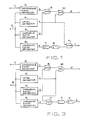
- Fig. 3 illustrates the circuit of a protective relay according to the present invention.
- Signals 1 and 2 mentioned already are supplied to the detectors 3, 4, 5 and 6 which were already mentioned in connection with Fig. 1 and which produce signals b, c, a, and e.
- the signal b is supplied to the first input of the AND gate 9, and the signal a is supplied to the second input which is an inverted logic input of the AND gate 9 which performs AND operation with these signals, and which produces an output which is applied to the first input of the OR gate 10.
- the OR gate 10 performs OR operation with the output of the gate 9 and the signal c of the detector 4, and produces a resulting signal dfor actuating the circuit breaker which is not shown.
- the signal c is supplied to the first input of the AND gate 11 of which the second input is served with the signal e of the detector 6.
- the AND gate 11 performs AND operation with the inverse of signal c and the signal e.
- the resulting signal is applied to the delay circuit 7 which has a delay time Td in operation, and then to the delay circuit 8 which has a delay time Th in restoration.
- an inhibit or lock signal g is produced by the delay circuit to inhibit the operation of the circuit breaker which is not shown.
- the detectors 3 to 6 In operation if the signal 2 is as shown in Fig. 4 like that of Fig. 2, the detectors 3 to 6 produce the signals b, c, a and e of high level respectively after the time to. Therefore, the gates 9 and 11 are blocked by the signals a and c so that the signal g is not generated. However, the signal c of the detector 4 causes the gate 10 to produce the actuating or protective signal d.
- the detector 6 produces the signal e of high level.
- the signal g is not produced.
- the detector 4 drops the signal c to low level and the detector 5 produces the signal a of high level. Therefore, the signal d is not produced from the gate 10 and the gate 11 opens since the signal c assumes a low level.
- the signal e assumes a low level.
- the time duration t 2 -t is shorter than the delay time Td of the delay circuit 7. Therefore, the delay circuit 7 is not allowed to produce output of high level. That is, the signal g is not yet supplied. In order to produce the signal g, there is required the condition that the gate 11 must be kept open for more than the delay time Td of the delay circuit 7.
Landscapes
- Engineering & Computer Science (AREA)
- Power Engineering (AREA)
- Emergency Protection Circuit Devices (AREA)
- Protection Of Transformers (AREA)
Claims (1)
- Schutzrelais zur Erzeugung von Signalen zum Schützen eines Objektes in einem Starkstromnetz abhängig von einem Differentialsignal (2); und einem Unterdrückungssignal (1), die von elektrischen Strömen abgeleitet werden, die an zwei getrennten Punkten des Objektes gemessen werden;mit einem ersten Detektor (3), der ein Signal mit einem ersten Zustand (b) erzeugt, wenn das Differentialsignal (2) um mehr als ein vorbestimmtes Verhältnis größer als das Ünterdrückungssignal (1) ist;mit einem zweiten Detektor (4), der ein Signal mit einem zweiten Zustand (c) erzeugt, wenn der Pegel des Differentialsignals (2) größer als ein vorbestimmter Wert ist;mit einem dritten (5) und einem vierten Detektor (6), die ein Signal mit einem dritten Zustand (a) bzw. ein Signal mit einem vierten Zustand (e) erzeugen, wenn die zweite harmonische Komponente in dem Differentialsignal (2) um mehr als ein vorbestimmtens Verhältnis größer als die Grundkomponente in dem Differentialsignal (2) ist;mit einer logischen Schaltung, die ein erstes UND-Gatter (9) enthält, dem das Signal mit dem ersten Zustand (b) zugeführt wird und das öffnet, wenn das Signal mit dem dritten Zustand (a) nicht zugeführt wird, die ein ODER-Gatter (10) enthält, das ein Schutzsignal (d) liefert und eine logische ODER-Funktion mit dem Ausgangssignal des ersten UND-Gatters (9) und dem Signal mit dem zweiten Zustand (c) durchführt, und ein zweites UND-Gatter (11) enthält, das eine logische UND-Funktion mit dem invertierten Wert des Signals mit dem zweiten Zustand (c) und dem Signal mit dem vierten Zustand (e) durchführt, um ein Sperrsignal zur Unterdrückung der Funktion des Schutzsignals (d) zu erzeugen;
gekennzeichnet durch eine Zeitgeberschaltung (7, 8), die mit dem Ausgang des zweiten UND-Gatters (11) verbunden ist und das Sperrsignal (g) erzeugt, wenn das Ausgangssignal des zweiten UND-Gatters (11) für länger als eine vorbestimmte Zeit markiert ist (Fig. 3).
Priority Applications (2)
| Application Number | Priority Date | Filing Date | Title |
|---|---|---|---|
| DE8585102567T DE3277670D1 (en) | 1981-12-29 | 1982-12-24 | Protective relay for a power system |
| DE8585102628T DE3279527D1 (en) | 1981-12-29 | 1982-12-24 | Protective relay for a power system |
Applications Claiming Priority (10)
| Application Number | Priority Date | Filing Date | Title |
|---|---|---|---|
| JP212415/81 | 1981-12-29 | ||
| JP56212415A JPS58116016A (ja) | 1981-12-29 | 1981-12-29 | 差動継電器 |
| JP57035393A JPS58154320A (ja) | 1982-03-05 | 1982-03-05 | 比率差動継電器 |
| JP35392/82 | 1982-03-05 | ||
| JP57035391A JPS58154318A (ja) | 1982-03-05 | 1982-03-05 | 保護継電器 |
| JP35391/82 | 1982-03-05 | ||
| JP35383/82 | 1982-03-05 | ||
| JP57035392A JPS58154319A (ja) | 1982-03-05 | 1982-03-05 | 保護継電器 |
| JP35393/82 | 1982-03-05 | ||
| JP57035383A JPS58154317A (ja) | 1982-03-05 | 1982-03-05 | 保護継電器 |
Related Child Applications (2)
| Application Number | Title | Priority Date | Filing Date |
|---|---|---|---|
| EP85102567.6 Division-Into | 1985-03-07 | ||
| EP85102628.6 Division-Into | 1985-03-08 |
Publications (2)
| Publication Number | Publication Date |
|---|---|
| EP0083097A1 EP0083097A1 (de) | 1983-07-06 |
| EP0083097B1 true EP0083097B1 (de) | 1986-04-09 |
Family
ID=27521690
Family Applications (3)
| Application Number | Title | Priority Date | Filing Date |
|---|---|---|---|
| EP85102567A Expired EP0161403B1 (de) | 1981-12-29 | 1982-12-24 | Schutzrelais für Starkstromnetze |
| EP82112011A Expired EP0083097B1 (de) | 1981-12-29 | 1982-12-24 | Schutzrelais für Starkstromnetze |
| EP85102628A Expired EP0161407B1 (de) | 1981-12-29 | 1982-12-24 | Schutzrelais für Starkstromnetze |
Family Applications Before (1)
| Application Number | Title | Priority Date | Filing Date |
|---|---|---|---|
| EP85102567A Expired EP0161403B1 (de) | 1981-12-29 | 1982-12-24 | Schutzrelais für Starkstromnetze |
Family Applications After (1)
| Application Number | Title | Priority Date | Filing Date |
|---|---|---|---|
| EP85102628A Expired EP0161407B1 (de) | 1981-12-29 | 1982-12-24 | Schutzrelais für Starkstromnetze |
Country Status (5)
| Country | Link |
|---|---|
| US (1) | US4513344A (de) |
| EP (3) | EP0161403B1 (de) |
| AU (1) | AU557935B2 (de) |
| CA (1) | CA1193707A (de) |
| DE (1) | DE3270515D1 (de) |
Families Citing this family (6)
| Publication number | Priority date | Publication date | Assignee | Title |
|---|---|---|---|---|
| AU560683B2 (en) * | 1982-06-23 | 1987-04-16 | Mitsubishi Denki Kabushiki Kaisha | Protective relay with second harmonic suppression |
| JPS6110911A (ja) * | 1984-06-27 | 1986-01-18 | 三菱電機株式会社 | 変圧器保護継電器 |
| US4903163A (en) * | 1989-05-09 | 1990-02-20 | The United States Of America As Represented By The Secretary Of The Interior | Directional harmonic overcurrent relay device |
| JP2676704B2 (ja) * | 1989-08-30 | 1997-11-17 | 三菱電機株式会社 | 差動保護継電装置 |
| US5172329A (en) * | 1990-06-14 | 1992-12-15 | Rahman Azizur M | Microprocessor-based digital protective relay for power transformers |
| RU2222248C1 (ru) | 2002-08-30 | 2004-01-27 | Общество с ограниченной ответственностью "Ю.Т.М." | Стеллажная конструкция |
Family Cites Families (2)
| Publication number | Priority date | Publication date | Assignee | Title |
|---|---|---|---|---|
| DE2451353C2 (de) * | 1974-10-29 | 1976-08-19 | Siemens AG, 1000 Berlin und 8000 München | Schutzschaltungsanordnung für einen Hochspannungskondensatorblock |
| JPS55101019A (en) * | 1979-01-29 | 1980-08-01 | Kaoru Yamazaki | Platform balance |
-
1982
- 1982-12-24 EP EP85102567A patent/EP0161403B1/de not_active Expired
- 1982-12-24 DE DE8282112011T patent/DE3270515D1/de not_active Expired
- 1982-12-24 EP EP82112011A patent/EP0083097B1/de not_active Expired
- 1982-12-24 EP EP85102628A patent/EP0161407B1/de not_active Expired
- 1982-12-24 AU AU91866/82A patent/AU557935B2/en not_active Ceased
- 1982-12-28 US US06/454,066 patent/US4513344A/en not_active Expired - Lifetime
- 1982-12-29 CA CA000418671A patent/CA1193707A/en not_active Expired
Also Published As
| Publication number | Publication date |
|---|---|
| EP0161407A1 (de) | 1985-11-21 |
| AU9186682A (en) | 1983-07-07 |
| EP0161403B1 (de) | 1987-11-11 |
| DE3270515D1 (en) | 1986-05-15 |
| EP0161403A1 (de) | 1985-11-21 |
| EP0083097A1 (de) | 1983-07-06 |
| CA1193707A (en) | 1985-09-17 |
| US4513344A (en) | 1985-04-23 |
| AU557935B2 (en) | 1987-01-15 |
| EP0161407B1 (de) | 1989-03-08 |
Similar Documents
| Publication | Publication Date | Title |
|---|---|---|
| EP0083097B1 (de) | Schutzrelais für Starkstromnetze | |
| US4477854A (en) | Portective relay with second harmonic suppression | |
| US5793594A (en) | Predictive control circuit and method for circuit interrupter | |
| US5157575A (en) | Circuit breaker failure relay system for power transmission line systems | |
| GB1254131A (en) | Improvements in static network protective relay | |
| US4661877A (en) | Transformer protective relay | |
| US3976920A (en) | Filtering arrangement for relay protection devices | |
| EP0087700A1 (de) | System zum Erfassen einer vorbestimmten Phasenverschiebung zwischen zwei in einem elektrischen Energie-System erfassten elektrischen Grössen | |
| JPH0121687B2 (de) | ||
| JPS5854572B2 (ja) | 搬送保護継電装置 | |
| SU1157607A1 (ru) | Устройство дл токовой защиты от короткого замыкани и перегрузки | |
| JPH04212A (ja) | 地絡検出装置 | |
| JPH0113302B2 (de) | ||
| SU1171975A1 (ru) | Усилитель с адаптивной широтно-импульсной модул цией | |
| RU1802895C (ru) | Устройство дл дифференциальной токовой защиты с торможением | |
| JPS6366138B2 (de) | ||
| JPS58154317A (ja) | 保護継電器 | |
| SU1749967A1 (ru) | Устройство дл защиты от замыкани на землю обмотки статора генератора | |
| JPH03245724A (ja) | 保護継電器 | |
| JP3120563B2 (ja) | 再閉路方式 | |
| JP2556927B2 (ja) | 変圧器保護用比率差動継電器 | |
| JP2001177977A (ja) | ディジタル形保護継電装置 | |
| JPS58154318A (ja) | 保護継電器 | |
| JPS63213409A (ja) | 保護継電装置 | |
| JPH09247845A (ja) | 比率差動継電器 |
Legal Events
| Date | Code | Title | Description |
|---|---|---|---|
| PUAI | Public reference made under article 153(3) epc to a published international application that has entered the european phase |
Free format text: ORIGINAL CODE: 0009012 |
|
| AK | Designated contracting states |
Designated state(s): DE GB SE |
|
| 17P | Request for examination filed |
Effective date: 19831102 |
|
| GRAA | (expected) grant |
Free format text: ORIGINAL CODE: 0009210 |
|
| AK | Designated contracting states |
Kind code of ref document: B1 Designated state(s): DE GB SE |
|
| REF | Corresponds to: |
Ref document number: 3270515 Country of ref document: DE Date of ref document: 19860515 |
|
| PLBE | No opposition filed within time limit |
Free format text: ORIGINAL CODE: 0009261 |
|
| STAA | Information on the status of an ep patent application or granted ep patent |
Free format text: STATUS: NO OPPOSITION FILED WITHIN TIME LIMIT |
|
| 26N | No opposition filed | ||
| PGFP | Annual fee paid to national office [announced via postgrant information from national office to epo] |
Ref country code: SE Payment date: 19921214 Year of fee payment: 11 Ref country code: GB Payment date: 19921214 Year of fee payment: 11 |
|
| PGFP | Annual fee paid to national office [announced via postgrant information from national office to epo] |
Ref country code: DE Payment date: 19930115 Year of fee payment: 11 |
|
| PG25 | Lapsed in a contracting state [announced via postgrant information from national office to epo] |
Ref country code: GB Effective date: 19931224 |
|
| PG25 | Lapsed in a contracting state [announced via postgrant information from national office to epo] |
Ref country code: SE Effective date: 19931225 |
|
| GBPC | Gb: european patent ceased through non-payment of renewal fee |
Effective date: 19931224 |
|
| PG25 | Lapsed in a contracting state [announced via postgrant information from national office to epo] |
Ref country code: DE Effective date: 19940901 |
|
| EUG | Se: european patent has lapsed |
Ref document number: 82112011.0 Effective date: 19940710 |