EP0083122A2 - Buse à réaction et procédé pour atomiser et mélanger des matériaux réactifs liquides - Google Patents
Buse à réaction et procédé pour atomiser et mélanger des matériaux réactifs liquides Download PDFInfo
- Publication number
- EP0083122A2 EP0083122A2 EP82201562A EP82201562A EP0083122A2 EP 0083122 A2 EP0083122 A2 EP 0083122A2 EP 82201562 A EP82201562 A EP 82201562A EP 82201562 A EP82201562 A EP 82201562A EP 0083122 A2 EP0083122 A2 EP 0083122A2
- Authority
- EP
- European Patent Office
- Prior art keywords
- mixing chamber
- discharge orifice
- nozzle
- fluid
- mixing
- Prior art date
- Legal status (The legal status is an assumption and is not a legal conclusion. Google has not performed a legal analysis and makes no representation as to the accuracy of the status listed.)
- Withdrawn
Links
Images
Classifications
-
- B—PERFORMING OPERATIONS; TRANSPORTING
- B01—PHYSICAL OR CHEMICAL PROCESSES OR APPARATUS IN GENERAL
- B01J—CHEMICAL OR PHYSICAL PROCESSES, e.g. CATALYSIS OR COLLOID CHEMISTRY; THEIR RELEVANT APPARATUS
- B01J19/00—Chemical, physical or physico-chemical processes in general; Their relevant apparatus
- B01J19/26—Nozzle-type reactors, i.e. the distribution of the initial reactants within the reactor is effected by their introduction or injection through nozzles
-
- B—PERFORMING OPERATIONS; TRANSPORTING
- B01—PHYSICAL OR CHEMICAL PROCESSES OR APPARATUS IN GENERAL
- B01F—MIXING, e.g. DISSOLVING, EMULSIFYING OR DISPERSING
- B01F25/00—Flow mixers; Mixers for falling materials, e.g. solid particles
- B01F25/30—Injector mixers
- B01F25/31—Injector mixers in conduits or tubes through which the main component flows
- B01F25/311—Injector mixers in conduits or tubes through which the main component flows for mixing more than two components; Devices specially adapted for generating foam
-
- B—PERFORMING OPERATIONS; TRANSPORTING
- B05—SPRAYING OR ATOMISING IN GENERAL; APPLYING FLUENT MATERIALS TO SURFACES, IN GENERAL
- B05B—SPRAYING APPARATUS; ATOMISING APPARATUS; NOZZLES
- B05B7/00—Spraying apparatus for discharge of liquids or other fluent materials from two or more sources, e.g. of liquid and air, of powder and gas
- B05B7/02—Spray pistols; Apparatus for discharge
- B05B7/04—Spray pistols; Apparatus for discharge with arrangements for mixing liquids or other fluent materials before discharge
-
- B—PERFORMING OPERATIONS; TRANSPORTING
- B01—PHYSICAL OR CHEMICAL PROCESSES OR APPARATUS IN GENERAL
- B01J—CHEMICAL OR PHYSICAL PROCESSES, e.g. CATALYSIS OR COLLOID CHEMISTRY; THEIR RELEVANT APPARATUS
- B01J2219/00—Chemical, physical or physico-chemical processes in general; Their relevant apparatus
- B01J2219/00049—Controlling or regulating processes
- B01J2219/00162—Controlling or regulating processes controlling the pressure
-
- B—PERFORMING OPERATIONS; TRANSPORTING
- B01—PHYSICAL OR CHEMICAL PROCESSES OR APPARATUS IN GENERAL
- B01J—CHEMICAL OR PHYSICAL PROCESSES, e.g. CATALYSIS OR COLLOID CHEMISTRY; THEIR RELEVANT APPARATUS
- B01J2219/00—Chemical, physical or physico-chemical processes in general; Their relevant apparatus
- B01J2219/00049—Controlling or regulating processes
- B01J2219/00164—Controlling or regulating processes controlling the flow
Definitions
- the present inventicn relates to nozzles having an internal mixing chamber and to a method of atomizing and mixing fluid reactants.
- the present invention relates to a nozzle in which an acid can be_continuously neutralized by a base to form a powdery or highly viscous product.
- Nozzles have been designed to accomplish a variety of mixing and atomization tasks with a large variety of fluids and gases.
- the mixing and/or atomization in conventional nozzles is usually accomplished by a forceful uniting of the liquids and gases either internally in a mixing chamber or externally by directing the liquids into each other's pathway.
- the nozzle is usually designed to facilitate the forceful joining of the fluids in order to induce a sudden high turbulence.
- U.S. Patent 3,764,069 issued to P. W. Runstadler, Jr. on October 9, 1973 discloses a method and apparatus for atomizing and spraying liquids.
- the liquid to be sprayed is supplied under a pressure of from 2-7 atmospheres (gauge) through liquid passage 43 and is caused to flov- in a thin film through annular flow passage 68.
- Streams of gas at a slightly higher pressure are impinged against the liquid film such that the air-to-liquid mass ratio is from 0.1 to 1.6 and such that the gas is sheared and broken up into microbubbles which are entrained in the liquid .to form a froth.
- the mixture is then directed through section 89 and through passageway 75 where the pressure decreases gradually so that the bubbles tend to expand slightly, thereby tending to make the froth mixture become more homogeneous.
- the mixture is then discharged through nozzle orifice 78 whereupon the air bubbles explode, rupturing the liquid film and causing the liquid to disintegrate into finely atomized drops.
- U.S. Patent 3,719,325 issued to A. Cerva et al. on March 6, 1973 discloses a nozzle for a pneumatic-hydraulic head for cleaning of molds for pressure casting of metal and depositing a layer of separating material on the mold surface.
- the nozzle comprises a nozzle head 1 having a central passageway 7, an annular passageway 9 and a chamber 10, a nozzle body 2 centrally located in chamber 10 such that there is a narrow annular passageway between the inner wall of chamber 10 and the outer wall of body 2 and having a central passageway 4 that connects with passageway 7, and hood 6 having a swirl chamber 12 and discharge orifice 8.
- Pressurized air is directed through passageway 9 and chamber 10 into spiral-shaped mixing channel 11 that is formed between part of the inner wall of hood 6 and part of the outer wall of body 2.
- the liquid separating material is directed through passageways 7 and 4 and then via transfer channel 5 into mixing channel 11 where it is thoroughly mixed with the air.
- the mixture is then swirled through chamber 12, which causes the separating material to be atomized, and the mixture is then discharged through orifice 8.
- U.S. Patent 1,995,934 issued to W. B. Mangold on March 26, 1935 discloses a gas burner having several concentric channels for feeding several different fluids.
- a central passageway 10 is for air only.
- the surrounding shorter annular passageway 24 is for gas and it mixes internally with air from a third passageway 14 which surrounds passageway 24.
- the mixing of the gas from passageway 24 and air from passageway 14 is further facilitated by double conical screen 28.
- Two additional annular passageways for air which surround passageway 15, direct additional streams of air to the burner exit where the unmixed air mixes with the air and gas mixture exiting from passageway 15.
- U.S. Patent 3,717,306 issued to J. R. Hushon et al. discloses a nozzle for spraying foaming materials.
- the nozzle comprises two concentric nozzle members.
- One material 18 flows through the central nozzle via the concentric channel 12, tangentially into the central annular space 13 which causes it to swirl as it flows through outlet end 10.
- the second material 16 flows through the annular chamber 15, and into space 28 via the tangentially disposed openings 29 which causes it to swirl as it empties, along with the first material, into space 30 where the materials are mixed and reacted to form the foam product.
- a further method for mixing and 'atomizing involves externally mixing the several materials.
- U.S. Patent 3,929,291 issued to G. Ladisch on December 30, 1975 discloses a spray mixing nozzle for reacting acid and base.
- the nozzle comprises a central pressurized gas channel 1, at least two surrounding annular channels 2 and 3 for acid and base and an outer annular channel for pressurized gas.
- the discharge outlet of the outer annular channel tapers conically and discharges the pressurized gas in a converging direction to thereby force the acid and base against the central air discharge and forcefully mix and atomize the acid and base so that they will react.
- the ratio of the throughflow diameters for the pressure gas in the central pressure gas channel and in the outer annular gas channel is preferably in a ratio of from 1:3 to 1:10 -
- the nozzle also includes a water spray nozzle 12 that directs a stream of water against the spray mixing nozzle to prevent a buildup of a crust that can frequently form when spraying highly concentrated acids with concentrated alkali solutions.
- Canadian patent No. 880,212 which issued to O. Pfrengle on April 22, 1970, discloses a process for reacting a basic liquid phase with an acidic liquid phase and an air pressure mixing nozzle for carrying out the similar neutralization process.
- the nozzle is similar to the above-described Ladisch patent and comprises two concentric canals or ducts surrounding a central bore.
- the acidic liquid and the basic liquid are passed through the central bore and the inner of the two concentric canals.
- Compressed air between 1 and 4 atmospheres, gauge is passed through the outer canal.
- the discharge exits from the two concentric canals are generally conically tapered so that the liquids and gas will impinge on one another.
- the liquids are atomized by the air pressure and are substantially mixed immediately after leaving the nozzle and any unmixed portion is mixed within a distance beyond the nozzle of from 300 to 800 centimeters. Upon mixing, the acid and base react to form a highly viscous product.
- an object of this invention is to provide a method and apparatus for atomizing and mixing liquids and/or gases internally in the apparatus.
- a further object of this invention is to provide a new method and apparatus for effecting and controlling a chemical reaction between the liquids and/or gases that have been mixed and atomized, internally in the apparatus to form a powdery or highly viscous product.
- a still further object of the invention is to provide a process for effecting a chemical reaction and for atomizing and mixing several liquids and/or gases that is both efficient and uses a minimum of energy.
- this invention provides for a nozzle reactor comprising a spray nozzle having a distal end with a discharge orifice therein and an internal mixing chamber of generally cylindrical form with its axis extending in the direction of fluid movement therethrough.
- the mixing chamber which is in communication and axially aligned with said discharge orifice, has an axially extending upper section with a cross sectional area substantially greater than that of the discharge orifice and a lower section having a generally conically shaped wall therein which provides the transition from the upper section to said discharge orifice.
- a plurality of concentric, axially aligned channels terminate at an end of said mixing chamber remote from said discharge orifice.
- the channels include a central channel and at least one intermediate channel of annular section, each of which is adapted to be connected to a source of fluid reactant.
- An outermost channel of annular section is adapted to be connected to a source of pressurized gas.
- the side wall of said upper section of said mixing chamber is generally aligned with the outer wall of said outermost channel.
- the invention also provides a method for atomizing and mixing fluid reactants which comprises transporting separately streams of at least two fluid reactants along concentric paths at velocities of less than 3 meters per second and a stream of pressurized gas at a velocity of at least
- the fluid reactants and gas are discharged axially into a generally cylindrically shaped mixing chamber and flow in a generally axial direction within said mixing chamber to atomize and entrain the fluid reactants in the pressurized gas stream to form an atomized fluid.
- Turbulence is induced in the atomized fluid at a point in the mixing chamber in the immediate vicinity of an axially aligned discharge orifice to substantially homogeniously mix the reactants within the atomized fluid, causing them to react at that point and in the discharge orifice and issue from the discharge orifice as a spray of product.
- the conventional nozzle having means for internal mixing is usually designed to maximize turbulence at the point where the several materials (i.e., liquids or gases) are to meet.
- the object is to achieve an homogeneous mixture of the several materials:
- the apparatus such as nozzles, that have been designed for mixing have therefore included a number of means to achieve high turbulence, such as swirling the materials while they are being mixed, joining the materials at right angles to each other, driving the materials across or through barriers to effect a breakup of the streams of materials, etc.
- the high turbulence is induced well within the mixing chamber area of the nozzle.
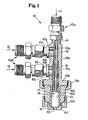
- the apparatus shown in Figure 1 and 2, can be used in the process of the present invention to internally mix materials that combine to form highly viscous products.
- the apparatus comprises, in Figure 1, a nozzle 10 having a nozzle body 10a which is elongated and has an axial bore therethrough. Near one end of the body 10a, an annular flange 10b projects outwardly and has its exterior surface threaded and adapted to engage the interior thread on retainer ring 10c, which clamps chamber extension cap 10d in position against the lower side of flange 10b and telescoped over the lower end of the body 10a, with the axial bores of each aligned.
- a cylindrical liner 10d' constructed of polytetrafluoroethylene or other material having non-stick properties, is telescoped within the bore of extension cap 10d, abutting the depending cylindrical lower end of nozzle body 10a.
- the lower end of the liner 10d' is tapered to match the conical lower surface of cap 10d.
- the lower end of cap 10d is exteriorly threaded and engages the interior thread of retainer ring 10e by means of which orifice member 10f is held in position against the lower end of cap 10d and of liner 10d'. This presses the liner 10d' against the lower end of nozzle body 10a.
- bosses lOg and 10h On the upper side of the body 10a bosses lOg and 10h have threaded studs 10i and 10j, respectively, threaded into or press-fit into through-bores interconnecting with the axial bore of the body 10a.
- Axial passageways 10k and 10L through studs 10i and 10j, respectively, are placed into communication with a source of fluid reactant 12 and a source of pressurized gas 13, respectively, by means of appropriate connector assemblies 10m.
- exterior threads permit mounting connector assembly 10n thereon, placing the axial bore of the body 10a in communication with a source of fluid reactant 11.
- the axial bore of the body 10a is machined to have four different diameters, the largest being at the bottom and diminishing in size as the upper end of the body 10a is approached.
- the varying diameters of the axial bore of body 10a are located and sized, as shown, to permit the cantilever- ing therein by any appropriate means of two concentric tubes 10p and 10q.
- the apparatus described results in a nozzle 10 having a central channel 14 and two concentric annular channels 15 and 16 surrounding it.
- the two materials e.g. fluid reactants 11 and 12, that are to be combined are directed through the central channel 14 and the inner annular channel 15, respectively, while a pressurized gas 13 is simultaneously directed through the outer annular channel 16.
- the nozzle 10 also includes a small, generally cylindrical mixing chamber 17, into which the two fluid reactants 11 and 12 and the pressurized gas 13 are directed, and a discharge orifice 20 located at the distal end of the nozzle.
- the two fluid reactants 11 and 12 and the pressurized gas 13 are all directed axially into the mixing chamber in order to minimize the amount of turbulence, and thereby control the mixing that occurs at the initial meeting point, in the upper section 18 of mixing chamber 17.
- the nozzle 10 is designed to initially atomize the two fluid reactants 11 and 12 before substantial mixing occurs.
- the pressurized air 13 enters the mixing chamber 17. at a high velocity relative to the two fluid reactants 11, 12 and acts to strip the fluid streams, breaking the fluids into fine particle sizes.
- This atomization takes place in the upper section 18 of the mixing chamber 17 and is substantially completed, such that the fluid reactants 11 and 12 are both broken down into relatively small particle sizes, before the atomized fluids 11 and 12 and the gas 13 reach the lower section 19 of the mixing chamber near the discharge orifice 20.
- the diameter of the discharge orifice 20 is sized to force a sudden, violent mixing of the atomized fluids 11 and 12 and the air 13.
- the mixing that occurs is sufficiently close to the discharge orifice 20 to ensure that the mixing fluids will be discharged rather quickly after they are combined. This is very important in the case of the mixing of materials that combine to produce highly viscous products since the viscous product will not have time to completely form before it is driven from the mixing chamber 17 and into the discharge orifice 20 by the high velocity pressurized air.
- the diameter of the discharge orifice 20 needs to be sized to produce a pressure drop of at least 2 atmospheres and - preferably greater than 3 atmospheres in order to produce sufficient turbulence for a thorough mixing to occur and for the chemical reaction between the already atomized liquids 11 and 12 to be substantially completed.
- the desired particle size may be different and therefore the desired pressure drop, which correlates to the desired particle size, can be readily determined by one of ordinary skill in the art.
- the central channel 14 is 2.2 mm diameter
- the inner annular channel 15 has a 3.2 mm inner diameter
- the outer annular channel 16 has a 6.4 mm inner diameter and a 6.9 mm outer diameter.
- the mixing chamber 17 includes a generally cylindrical upper section 18 where the atomization occurs and a relatively short lower section 19 having a conically tapered lower wall that lies at an included angle with the side wall of the mixing chamber that is preferably between 90° and 165°, and that converges to the centrally located orifice 20.
- the upper section 18 of mixing chamber 17 has a 6.9 mm diameter and is 16.5 mm long and the lower section 19 has an entry diameter of 6.9 mm that tapers symmetrically inwardly at an included angle of 143 0 to an exit diameter of 2.3 mm.
- the discharge orifice 20 is cylindrical in shape and is 2.3 mm in diameter and 5.7 mm in length.
- the walls of the upper section 18 could also be tapered inwardly as long as the turbulence that is induced is not sufficient to cause an early formation of the highly viscous or powdery resulting product.
- the upper section 18 was preferably substantially cylindrical.
- the lower section 19 of the mixing chamber 17 should still have the sharply converging walls and the relatively narrow discharge orifice 20 in order to create the necessary turbulence for rapid mixing of the acid and base. Additionally, it has been found that it is preferable to align the outer annular channel 16 for the pressurized gas 13 to the side or inner wall 21 of the mixing chamber 17 such that the gas 13 provides a constant cleaning action along the walls 21 to minimize the possibility of a buildup of either the fluids 11 and 12 or of the resulting product of their reaction along the wall. Hence the outer diameter of the outer annular channel 16 is substantially similar to the diameter of upper section 18 of mixing chamber 17.
- the process for atomizing and mixing the materials to be reacted begins with the atomization of the materials.
- the materials to be combined such as the acidic liquid and the basic liquid described in Example 1, below, are directed in stoichiometric rates into the upper section 18 of the mixing chamber 17 via the central channel 14 and the intermediate annular channel 15 at relatively low speeds of less than 3.0 meters per second, preferably less than 1.5 meters per second, and at a pressure of 2 atmospheres.
- 2 atmospheres preferably at least 3 atmospheres, is simultaneously directed into the upper section 18 of the mixing chamber 17 via the outer annular channel 16 at a .relatively high rate of speed of at least 15 meters per second, preferably greater than 30 meters per second.
- the differential in the speeds between pressurized air and the two fluid reactants, e.g. the acid and base, must be sufficient to atomize the two fluid-reactants as the three fluids enter the upper section of the mixing chamber 17.
- the acidic liquid and the basic liquid must be at least partially atomized and entrained in the air stream and also distributed substantially homogeneously in the air stream when the mixture reaches the lower section 19 of the mixing chamber 17.
- the lower section 19 of the mixing chamber 17, as indicated, is designed to induce a sudden, high turbulence in the mixture such that the partially atomized acidic liquid and basic liquids are driven together to be substantially completely mixed and to thereby begin reacting and forming the highly viscous paste product.
- the mixture does not have enough time to proceed to a complete reaction since the mixture is being driven into and through the nozzle orifice 20 by the high velocity pressurized air, and the pressure of the incoming fluids.
- the bulk of the reaction therefore occurs within the discharge orifice 20 and preferably is completed when the materials in spray form exit from the discharge orifice 20, although with a pressure drop across the orifice of close to the minimum acceptable 2.0 atmospheres, the reaction may not be completed until a very short distance beyond the nozzle 10. The higher the pressure drop across the orifice 20 the more likely it is that the reaction will be completed before the materials exit from the orifice 20.
- the best results are achieved when the more viscous of the acidic liquid and the basic liquid is directed through the intermediate annular channel 15. This allows the air to act quickly in atomizing the outermost, and more viscous, of the fluid reactants first before atomizing the less viscous fluid.
- the upper section 18 of the mixing chamber 17 into which the three fluids are directed is generally cylindrical in shape.
- mixing chamber 17 preferably has a length-to-diameter ratio of between
- the length of the mixing chamber may have to be designed to minimize residence time of the fluid reactants within the mixing chamber.
- the design for the lower section 19 is principally directed toward developing a high degree of turbulence at that point in the mixing chamber 17 to complete the atomization and to substantially homogeneously mix the materials immediately prior to passage through the discharge orifice 20.
- the orifice is preferably centrally positioned relative to the inner walls of the upper section 18 of the mixing chamber 17. It has been found that where the discharge orifice 20 is centrally located the diameter of the discharge orifice should be sized to produce a pressure drop of at least 2 atmospheres with the preferred pressure drop being at least 3 atmospheres. With this information, a good estimate of the orifice diameter can be obtained by using the "orifice equation", as disclosed in Chapter 5, at page 11 in Perry, R.
- the reaction that occurs in combining the atomized organic acidic liquid with long carbon chains, e.g. alkylaryl sulfonic acid and alkyl sulfuric acid, and the atomized concentrated basic liquid, e.g. 50% sodium hydroxide solution, is a neutralization reaction that produces either a powdery or a highly viscous anionic surfactant paste product, and energy in the form of heat.
- the viscosity of the resulting paste product %ill generally dcpend on the amount of moisture in the final paste product, and the amount of moisture is directly related to the amount of water in the concentrated basic liquid which is usually a solution of a basic material and water.
- the homogeneity of the paste i.e. the absence of unreacted acid or base, is a function of the gas to stock mass ratio, where the stock mass is the combined total mass of the acid and base materials entering the mixing chamber 17.
- a minimum air to stock mass ratio of 0.3 and preferably of 0.4 is needed. This is considerably less than the value of 2.0 that is suggested as required for good atomization for external atomizing nozzles in such texts as K. Master, Spray Drying Handbook, John Wiley & Sons, New York (1979). Also it has been determined that the minimum air to stock mass ratio is independent of the stock flow rates.
- the above-described nozzle 10 is especially useful in combining, i.e. atomizing and mixing, unstable organic acidic liquids, such as organic sulfuric acids, e.g. aklyl sulfuric acid and alkyl exothylated sulfuric acid, with basic liquids such as sodium hydroxide, potassium hydroxide, sodium carbonate and potassium carbonate.
- unstable organic acidic liquids such as organic sulfuric acids, e.g. aklyl sulfuric acid and alkyl exothylated sulfuric acid
- basic liquids such as sodium hydroxide, potassium hydroxide, sodium carbonate and potassium carbonate.
- the prior art method of externally atomizing and mixing acidic and basic materials would work satisfactorily for stable acidic liquids, such as organic sulfonic acids, since there is no time constraint for reacting the stable acidic liquids with a basic liquid.
- Unstable acidic liquids such as the organic sulfuric acids must be substantially neutralized quickly or they will hydrolyze to the acid's starting materials.
- the length and time over which the reaction occurs can be controlled and minimized.
- the unstable acidic liquid can therefore be substantially, com pletely reacted before it begins to hydrolyze.
- special attention must be paid to the process to ensure that there is no localized, unreacted acidic material left in the resulting product, since that unreacted acidic material will hydrolyze and result in reduced yield from the -reaction.
- a stable acidic liquid is being neutralized any unreacted acidic materials will not hydrolyze and can be neutralized at a later point in the process.
- a universal pH indicator can be used in a test in which the indicator is adjusted to a pH of 12 with sodium hydroxide solution and sprayed on a filter paper clamped onto a suitable frame. The filter paper is then quickly carried through the spray of product along a horizontal plane 15 inches below the reactor nozzle. A change of color in spots indicates the presence of unneutralized acid particles.
- an acidic material such as a mixture of alkylaryl sulfonic acid and sulfuric acid
- a basic material such as a sodium hydroxide solution
- sodium sulfate (Na 2 SO 4 ) is one of the chemical products of the fluid reactants
- the basic material is supplied in a solution with water, and the concentration of the basic material in the solution will directly affect the level of moisture in the final anionic surfactant paste product.
- NazSO 4 sodium sulfate
- the paste moisture was in the range of 15-22% by weight (due to the solubility of the basic material, e.g. sodium hydroxide, the practical achievable lower limit of paste moisture is approximately 15%) there was no clogging; between the range of 22-32% the clogging potential increased with increasing paste moisture, and above approximately 32% paste moisture the clogging potential decreased.
- one easily applied and inexpensive solution to the clogging problem is to periodically purge the nozzle with water.
- the water can be added through the caustic feed line when clogging is sensed by a loss of air flow rate.
- the water flow can continue for a predetermi'ned period sufficient to dissolve and carry away the sodium sulfate.
- This solution is particularly adapted to solve the specific clogging problem associated with the use of the nozzle of the present invention in the preferred application of reacting an acid and a base that produces sodium sulfate.
- Other applications of the nozzle and other fluid reactants may produce different problems unique to the materials being combined.
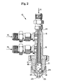
- FIG. 2 An alternative embodiment of the present nozzle invention, shown in Figure 2, is identical to the embodiment of Figure 1 but in addition it includes a multi-orifice, wide- angle spray cap 25 provided with central discharge passageway 22, and a standard vane 24, available from Spraying Systems Company of 26250 Euclid Avenue, Cleveland, Ohio 44132, as catalog number 27, which is placed adjacent the lower section 19 of the mixing chamber 17.
- the passageways 23 are symmetrically arranged in a conical pattern about the axis of the nozzle 10 as, for example, six passageways 23 equally spaced at 60° intervals.
- Each of the passageways 23 is skewed -with respecf to the other and to the axis of the nozzle 10 but as a whole the passageways 23 have the combined effect of an axially aligned discharge orifice.
- the total discharge cross-sectional area of the passageways 23 in the cap is designed to be approximately equal to the cross-sectional area of the single central discharge passageway 22. Dividing the spray in this manner reduces the downward momentum of the paste particles, and, more importantly, provides a wider spray angle.
- the vane 24 is employed to further reduce the downward momentum of the paste particles and to increase the turbulent mixing of the air and the reactants in the lower section 19 of the mixing chamber 17 to thereby slightly reduce the amount of pressurized air that is required to produce the homogeneous paste.
- the reactor nozzle was fed with the following materials (all percentages are by weight):
- the materials were fed continuously to the nozzle and upon exiting the discharge orifice 22 the materials had combined to produce a white, highly viscous paste product having a bulk density of 1.0 gm/cc and a pH of a 1% solution of 11.
- the paste was composed of 21% sodium alkyl sulfate, 17% sodium alkyl ethoxyl sulfate, 17% sodium alkylaryl sulfonate, 27% sodium sulfate and the remaining 18% was water.
- This product has utility as an ingredient for detergent compositions and can, for example, be directed to impinge upon a moving powder substrate for agglomeration purposes.
- the nozzle was operated continuously for 4 hours and showed no sign of clogging. In addition, there was no evidence of any buildup along the walls of either the mixing chamber or the discharge orifice.
- the reactor nozzle was fed with the following materials (all percentages are by-weight):
- the materials were fed continuously to the nozzle and upon exiting the discharge orifice 22 the materials had combined to produce a white, voluminous powder having a bulk density of 0.2 gm/cc and a pH of a 1% solution of
- the product was composed of 54% sodium alkylaryl sulfonate, 29% sodium sulfate and the remaining 17% was water and has utility as an ingredient for detergent compositions.
- the nozzle was operated continuously for more than 2 hours without any sign of clogging and there was no evidence of any buildup along the walls of either the mixing chamber or the discharge orifice. This result conforms with the graph of Figure 3 since a paste moisture of 17% is within the area designated A in which there was no clogging.
- the reactor nozzle was fed with the following materials (all percentages are by weight):
- the materials were fed continuously to the nozzle and upon exiting the discharge orifice 22 the materials had combined to produce a white, viscous paste having a bulk density of 1.0 gm/cc and a pH of a 1% solution of 11.2.
- the product was composed of 36% sodium alkylaryl sulfonate, 19% sodium sulfate and the remaining. 45% was water and has utility as an ingredient for detergent compositions.
- the nozzle began to experience a buildup of sodium sulfate along the walls of the discharge orifice rather quickly and the nozzle began to clog in approximately 30 minutes. This result conformed to the graph of Figure 3 for a paste moisture level of 45%. It was determined that the presence of a larger amount of water (over that present in the Example 2) and the subsequent increase in the moisture level of the paste product had caused a smaller amount of sodium sulfate to precipate out. At this level of precipitation, the sodium sulfate tended to cling to and build up along the walls of the discharge orifice and eventually clog the orifice. This clogging problem was corrected by purging the nozzle with 5 kg/hr of water for 30 sec. The sodium sulfate (Na 2 SO 4 ) dissolved and the nozzle returned to normal operation. To provide for a continuous operation the nozzle can be fed with water for 30 seconds at 30 minute intervals.
- the materials were fed continuously to the nozzle and upon exiting the discharge orifice 22 the materials had combined to produce a white foamy paste.
- the foaminess of the paste was due to the presence of C0 2 in the paste.
- the C0 2 quickly escaped into the air, dissipating the foamy texture of the paste.
- the paste had a bulk density of approximately 1.0 gm/cc and a pH of 3 in a 1% solution. Since a pH of 3 was still slightly acidic the paste needed to be subjected to a post treating step.
- the paste was quickly trimmed to a pH of 7 or above by mixing it with a 25% sodium hydroxide solution.
- the product was composed of 15% sodium alkyl _ sulfate, 12% sodium alkyl ethoxyl sulfate, 12% sodium alkyaryl sulfonate, 20% sodium sulfate and the remaining 41% was water and has utility as an ingredient for detergent compositions.
- the nozzle was operated for one hour and showed no sign of clogging and there was no evidence of any buildup along the walls of either the mixing chamber or the discharge orifice.
Landscapes
- Chemical & Material Sciences (AREA)
- Chemical Kinetics & Catalysis (AREA)
- Organic Chemistry (AREA)
- Nozzles (AREA)
Applications Claiming Priority (2)
| Application Number | Priority Date | Filing Date | Title |
|---|---|---|---|
| US06/334,275 US4462543A (en) | 1981-12-24 | 1981-12-24 | Nozzle |
| US334275 | 2002-12-31 |
Publications (2)
| Publication Number | Publication Date |
|---|---|
| EP0083122A2 true EP0083122A2 (fr) | 1983-07-06 |
| EP0083122A3 EP0083122A3 (fr) | 1984-10-03 |
Family
ID=23306446
Family Applications (1)
| Application Number | Title | Priority Date | Filing Date |
|---|---|---|---|
| EP82201562A Withdrawn EP0083122A3 (fr) | 1981-12-24 | 1982-12-09 | Buse à réaction et procédé pour atomiser et mélanger des matériaux réactifs liquides |
Country Status (3)
| Country | Link |
|---|---|
| US (1) | US4462543A (fr) |
| EP (1) | EP0083122A3 (fr) |
| ES (1) | ES518502A0 (fr) |
Cited By (9)
| Publication number | Priority date | Publication date | Assignee | Title |
|---|---|---|---|---|
| EP0272183A1 (fr) * | 1986-12-18 | 1988-06-22 | Soferti | Fabrication de phosphates d'ammonium contenant du sulfate d'ammonium |
| FR2613639A1 (fr) * | 1987-04-10 | 1988-10-14 | Reclus Edouard | Dispositif pour pulser et pulveriser, avec des gaz, des produits ou des melanges |
| US5189207A (en) * | 1987-12-07 | 1993-02-23 | Henkel Kommanditgesellschaft Auf Aktien | Process for the production of solid or paste-form products |
| WO1994018303A1 (fr) * | 1993-02-11 | 1994-08-18 | Henkel Kommanditgesellschaft Auf Aktien | Procede de production d'agents tensio-actifs granules |
| US5739097A (en) * | 1993-02-11 | 1998-04-14 | Henkel Kommanditgesellschaft Auf Aktien | Process for the production of surfactant granules |
| GB2351459A (en) * | 1999-05-21 | 2001-01-03 | Sec Dep Of The Home Dept | Component mixing and dispensing nozzle |
| WO2015036514A1 (fr) * | 2013-09-13 | 2015-03-19 | N.V. Nutricia | Ensemble buse d'atomisation de mélange interne, ainsi que procédé et produit associés |
| EP2883601A1 (fr) * | 2013-12-16 | 2015-06-17 | China Petrochemical Development Corporation, Taipei (Taiwan) | Dispositif de mélange de fluides |
| WO2024057209A1 (fr) * | 2022-09-15 | 2024-03-21 | Pfizer Inc. | Dispositif à flux coaxial pour préparation de nanoparticules et équipement de fabrication comprenant un tel dispositif |
Families Citing this family (20)
| Publication number | Priority date | Publication date | Assignee | Title |
|---|---|---|---|---|
| US5484107A (en) * | 1994-05-13 | 1996-01-16 | The Babcock & Wilcox Company | Three-fluid atomizer |
| US6386463B1 (en) * | 1996-05-13 | 2002-05-14 | Universidad De Sevilla | Fuel injection nozzle and method of use |
| JP3333699B2 (ja) * | 1996-11-22 | 2002-10-15 | 仲道 山崎 | 連続水熱反応における原料粒子噴霧方法および装置 |
| EP1037713B1 (fr) * | 1997-12-17 | 2002-07-10 | Universidad de Sevilla | Procede de production de gouttelettes creuses |
| AU784815B2 (en) * | 1997-12-17 | 2006-06-29 | Universidad De Sevilla | Device and method for creating aerosols for drug delivery |
| US6271275B1 (en) | 1998-08-17 | 2001-08-07 | Sealed Air Corp. (Us) | Method and apparatus for producing polyurethane foam |
| US20030039728A1 (en) * | 2001-08-21 | 2003-02-27 | Herrick James Peter | Device and method for on-demand dispensing of spoonable or drinkable food products having visual appearance of multi-components |
| US6969012B2 (en) | 2002-01-24 | 2005-11-29 | Kangas Martti Y O | Low pressure atomizer for difficult to disperse solutions |
| RU2236899C1 (ru) * | 2003-08-05 | 2004-09-27 | Федеральное государственное унитарное предприятие "Государственный научно-исследовательский институт химии и технологии элементоорганических соединений" | Реактор для проведения химических процессов |
| US7165733B2 (en) * | 2003-09-02 | 2007-01-23 | Karin M. Bolland | Sanitary spray nozzle |
| US7201815B2 (en) * | 2003-09-02 | 2007-04-10 | H.B. Fuller Licensing & Financing Inc. | Paper laminates manufactured using foamed adhesive systems |
| FR2859650B1 (fr) * | 2003-09-12 | 2006-02-24 | Gloster Sante Europ | Appareil de brumisation d'une composition liquide |
| US20050121827A1 (en) * | 2003-12-09 | 2005-06-09 | Lear Corporation | Method of heating in-mold coating composition |
| US20050274821A1 (en) * | 2004-06-11 | 2005-12-15 | Lear Corporation | Heated spray applicator |
| US7717059B2 (en) * | 2005-06-15 | 2010-05-18 | Spraying Systems Co. | Liquid adhesive dispensing system |
| US20060283980A1 (en) * | 2005-06-20 | 2006-12-21 | Wang Muh R | Atomizer system integrated with micro-mixing mechanism |
| US8973522B2 (en) * | 2011-03-14 | 2015-03-10 | Axalta Coating Systems Ip Co., Llc | Dual feeding spray device and use thereof |
| DE102017001025B4 (de) | 2017-02-03 | 2020-10-08 | Rs Rittel Gmbh | Verbrennungsanlage und Verfahren zur Abgasbehandlung |
| US12263499B2 (en) | 2018-08-03 | 2025-04-01 | Rs Rittel Gmbh | Nozzle lance, combustion plant and method for exhaust gas treatment |
| DE102022113593A1 (de) * | 2022-05-30 | 2023-11-30 | Westnetz Gmbh | Kompakte Mischungsvorrichtung zur Mischung von Fluiden |
Family Cites Families (17)
| Publication number | Priority date | Publication date | Assignee | Title |
|---|---|---|---|---|
| CA880212A (en) * | 1971-09-07 | Pfrengle Otto | Process for reacting a basic liquid phase with an acidic liquid phase | |
| US1798195A (en) * | 1928-10-09 | 1931-03-31 | Lyle N Dreibelbis | Soldering torch |
| US1995934A (en) * | 1933-09-18 | 1935-03-26 | Trust Company | Gas burner |
| US2760821A (en) * | 1954-04-05 | 1956-08-28 | Alfred L Kenworthy | Compound spray nozzles |
| US3010658A (en) * | 1959-11-06 | 1961-11-28 | Electro Chemical Engineering & | Spray gun |
| DE1542062A1 (de) * | 1966-04-07 | 1970-04-09 | Budenheim Rud A Oetker Chemie | Verfahren zur Herstellung von festen Aufsprueh- und Spruehmischprodukten |
| US3563459A (en) * | 1966-12-19 | 1971-02-16 | Robertson Co H H | Dispersion method |
| US3561677A (en) * | 1967-07-07 | 1971-02-09 | Gyromat Corp | Electrostatic air-liquid atomizing nozzle for paints and the like |
| US3458138A (en) * | 1967-09-14 | 1969-07-29 | Crompton & Knowles Corp | Spray gun |
| US3561680A (en) * | 1968-09-16 | 1971-02-09 | Respond Inc | Spray head assembly |
| CS148180B1 (fr) * | 1970-08-14 | 1973-02-22 | ||
| US3717306A (en) * | 1971-03-10 | 1973-02-20 | Hushon R | Nozzle for spraying foaming materials |
| US3764069A (en) * | 1971-07-30 | 1973-10-09 | Nordson Corp | Method and apparatus for spraying |
| BE790131A (fr) * | 1971-10-14 | 1973-04-16 | Basf Ag | Procede et dispositif de melange de liquides |
| US3929291A (en) * | 1973-05-24 | 1975-12-30 | Pfrengle Otto | Spray mixing nozzle |
| DE2517715C2 (de) * | 1975-04-22 | 1977-02-10 | Hans Behr | Verfahren und einrichtung zum mischen und/oder dispergieren und abstrahlen der komponenten eines fliessfaehigen materials zum beschichten von oberflaechen |
| US4255125A (en) * | 1978-12-15 | 1981-03-10 | Exxon Research & Engineering Co. | Mixing apparatus and the uses thereof |
-
1981
- 1981-12-24 US US06/334,275 patent/US4462543A/en not_active Expired - Fee Related
-
1982
- 1982-12-09 EP EP82201562A patent/EP0083122A3/fr not_active Withdrawn
- 1982-12-23 ES ES518502A patent/ES518502A0/es active Granted
Cited By (12)
| Publication number | Priority date | Publication date | Assignee | Title |
|---|---|---|---|---|
| EP0272183A1 (fr) * | 1986-12-18 | 1988-06-22 | Soferti | Fabrication de phosphates d'ammonium contenant du sulfate d'ammonium |
| EP0272974A3 (en) * | 1986-12-18 | 1989-03-15 | Cdf Chimie Azote Et Fertilizants S.A. | Tubular reactor |
| FR2613639A1 (fr) * | 1987-04-10 | 1988-10-14 | Reclus Edouard | Dispositif pour pulser et pulveriser, avec des gaz, des produits ou des melanges |
| US5189207A (en) * | 1987-12-07 | 1993-02-23 | Henkel Kommanditgesellschaft Auf Aktien | Process for the production of solid or paste-form products |
| WO1994018303A1 (fr) * | 1993-02-11 | 1994-08-18 | Henkel Kommanditgesellschaft Auf Aktien | Procede de production d'agents tensio-actifs granules |
| US5739097A (en) * | 1993-02-11 | 1998-04-14 | Henkel Kommanditgesellschaft Auf Aktien | Process for the production of surfactant granules |
| GB2351459A (en) * | 1999-05-21 | 2001-01-03 | Sec Dep Of The Home Dept | Component mixing and dispensing nozzle |
| GB2351459B (en) * | 1999-05-21 | 2003-04-16 | Sec Dep Of The Home Dept | Improvements in and relating to the application of materials |
| WO2015036514A1 (fr) * | 2013-09-13 | 2015-03-19 | N.V. Nutricia | Ensemble buse d'atomisation de mélange interne, ainsi que procédé et produit associés |
| CN105612005A (zh) * | 2013-09-13 | 2016-05-25 | N.V.努特里奇亚 | 内部混合雾化喷射喷嘴组件、过程及产品 |
| EP2883601A1 (fr) * | 2013-12-16 | 2015-06-17 | China Petrochemical Development Corporation, Taipei (Taiwan) | Dispositif de mélange de fluides |
| WO2024057209A1 (fr) * | 2022-09-15 | 2024-03-21 | Pfizer Inc. | Dispositif à flux coaxial pour préparation de nanoparticules et équipement de fabrication comprenant un tel dispositif |
Also Published As
| Publication number | Publication date |
|---|---|
| EP0083122A3 (fr) | 1984-10-03 |
| ES8404200A1 (es) | 1984-05-01 |
| ES518502A0 (es) | 1984-05-01 |
| US4462543A (en) | 1984-07-31 |
Similar Documents
| Publication | Publication Date | Title |
|---|---|---|
| US4462543A (en) | Nozzle | |
| US4086663A (en) | Mixing apparatus and method | |
| US4191480A (en) | Continuous flow static mixer for mixing powder and/or suspension materials with liquid materials | |
| EP0477845B1 (fr) | Dispersion de gaz dans un liquide en ligne | |
| US4224295A (en) | Process for the production of finely divided silicic acid by spray drying | |
| CA1100481A (fr) | Traduction non-disponible | |
| JP5108935B2 (ja) | ポリウレタンの層を有する成形品を製造する方法および装置 | |
| US4022379A (en) | Process for reacting acid and base | |
| EP0057720B1 (fr) | Atomisation de gaz variable | |
| CA1137076A (fr) | Systeme melangeur par vaporisation de liquides a reaction chimique reciproque | |
| US20180229150A1 (en) | External mixing pressurized two-fluid nozzle and a spray drying method | |
| US4377344A (en) | Apparatus for bringing liquids in contact | |
| CN1972754B (zh) | 喷雾装置和用于流化床粒化的方法 | |
| CA2170599A1 (fr) | Procede pour l'obtention de percarbonate de sodium granulaire | |
| CA2825400A1 (fr) | Buse a deux fluides sous pression a melange externe et procede de sechage par pulverisation | |
| JPH11510426A (ja) | 流動層式噴霧造粒によりグラニュールを製造する方法および装置 | |
| CA2497865A1 (fr) | Procede et dispositif pour appliquer des liquides dans un ecoulement solide de dispositif a lit fluidise | |
| EP0860201B1 (fr) | Procédé pour réactions par collision à haute vitesse | |
| CA2315684A1 (fr) | Dispositif permettant de melanger puis de pulveriser des liquides | |
| CA1089486A (fr) | Appareil et methode de sulfonation | |
| US4533571A (en) | Method and apparatus for uniformly coating a substrate with a powder | |
| KR930006759B1 (ko) | 저압 분무제트장치 | |
| PL143671B1 (en) | Process for generating gaseous mixture of ammonia and isocyanic acid and apparatus therefor | |
| JPS5922579B2 (ja) | 液体を吹付けるための噴霧方法および装置 | |
| JPH04504819A (ja) | ミキサー |
Legal Events
| Date | Code | Title | Description |
|---|---|---|---|
| PUAI | Public reference made under article 153(3) epc to a published international application that has entered the european phase |
Free format text: ORIGINAL CODE: 0009012 |
|
| AK | Designated contracting states |
Designated state(s): BE DE FR GB IT NL |
|
| PUAL | Search report despatched |
Free format text: ORIGINAL CODE: 0009013 |
|
| AK | Designated contracting states |
Designated state(s): BE DE FR GB IT NL |
|
| 17P | Request for examination filed |
Effective date: 19850322 |
|
| STAA | Information on the status of an ep patent application or granted ep patent |
Free format text: STATUS: THE APPLICATION HAS BEEN WITHDRAWN |
|
| 18W | Application withdrawn |
Withdrawal date: 19860303 |
|
| RIN1 | Information on inventor provided before grant (corrected) |
Inventor name: YAM, BENNY SIN-HOI |