EP0083149A2 - Capteur de pluie - Google Patents
Capteur de pluie Download PDFInfo
- Publication number
- EP0083149A2 EP0083149A2 EP82305135A EP82305135A EP0083149A2 EP 0083149 A2 EP0083149 A2 EP 0083149A2 EP 82305135 A EP82305135 A EP 82305135A EP 82305135 A EP82305135 A EP 82305135A EP 0083149 A2 EP0083149 A2 EP 0083149A2
- Authority
- EP
- European Patent Office
- Prior art keywords
- conductor
- rain sensor
- carrier plate
- heating
- resistant
- Prior art date
- Legal status (The legal status is an assumption and is not a legal conclusion. Google has not performed a legal analysis and makes no representation as to the accuracy of the status listed.)
- Withdrawn
Links
Images
Classifications
-
- G—PHYSICS
- G01—MEASURING; TESTING
- G01W—METEOROLOGY
- G01W1/00—Meteorology
Definitions
- the invention relates to a rain sensor having an insulating carrier plate and a plurality of conductor paths disposed on the carrier plate which are combined into two groups of electrodes which are electrically connected between one another but electrically separated from one another with close interlacing.
- Rain sensors are used, in particular, for control and regulating purposes, for example for the control of ventilators in buildings and should give a reliable signal of precipitation occurring. Since they are exposed to atmospheric influences for this purpose, they are subject to corrosion in continuous service. In particular, however, they can only be used if they give an appropriate signal on onset of precipitation, even under difficult conditions, and do not fail, for example due to icing up or give false signals in the case of dew.
- a rain sensor of the kind indicated at the beginning which has already been used in practice is constructed essentially in the manner of a "printed" circuit board, common in the electronic field, in that a carrier plate of glass-fibre reinforced plastics material carries comb-shaped conductors. Such a plate is disposed on the top of a housing and heated from below so that a reliable signal can be achieved even in the case of ice, snow and dew. For this purpose, the plate is connected to a separate heating element.
- connection to a heating element is expensive in equipment and unreliable, and in addition, the metal conductor paths are liable to disturbance as a result of atmospheric influences.
- Destructive influences result on the conductor paths in long-term operation, both in the sense of destruction of the conductors caused by corrosion and in the form of short-circuits between conductors which are usually etched, so that high reliability for the typical field of use of devices reacting automatically to atmospheric influences is not adequately met.
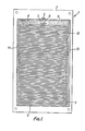
- the rain sensor plate illustrated in Figure 1 and designated as a whole by 1 consists of a carrier plate 2 of highly heat resistant and acid-resistant plastics material which is resistant to ultra violet light.
- the dimensions of the plate are about 100 x 170 mm, holes for screw mounting being machined in the corners.
- the plate is occupied by a dense pattern of narrow conductor paths which extend substantially parallel to one another and which in their main alignment, extend parallel to the narrow sides of the carrier plate 2.
- These conductor paths are constructed coherently with one another, however, so that altogether only two conductor-path groups, separated from one another, result as electrodes, namely a heating electrode 3 and a counter electrode 4.
- the heating electrode has two connection points 5 and 6, disposed in the region of widened soldering surfaces or soldering lugs, and the counter electrode 4 has one connection point 7 in the region of a conductor path which is widened as a whole. All three connection points 5, 6, 7 lie close together near the middle of one of the two narrow sides of the carrier plate 2.
- the conductor paths of the heating electrode 3 are constructed continuously in meandering form, in that they lead from a first conductor path 8 contacting the connection point 6 winding to the opposite side of the carrier plate 2 with a last conductor path 9 and from there return (along a narrow side of the carrier plate 2) with a connecting return conductor path 10 running round the outside of the connection point 5.
- a loop is provided which, with a flow of current in the loop, enables Joule's heat losses to be produced and so the plate to be heated:
- the conductor paths are formed from plastics material which is capable of conducting electricity so that they are extremely resistant to the weather and in addition, with a total resistance of 70 ohms for example present favourable connection values for the current supply of the heating means.
- the paths for the conductors are machined in the carrier plate 2 so that the conductors lie flush with the surface of the plate to form a plane surface termination, as a result of which, inter alia, dirt is prevented from settling on the plate and bridges caused by corrosion are prevented from forming from one conductor path to another. This benefits the operational reliability and durability of the rain sensor.
- the smooth-surfaced plate thus formed merely has to be appropriately connected up in order to obtain the desired heating between the connection points 5 and 6 and the monitoring of precipitation between one of the two connection points and the connection point 7 of the counter electrode.
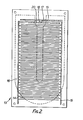
- Figure 2 shows a rain sensor plate 13, the surface of which is designed with the basic structure of conventional rain sensor plates in mind, that is to say with two comb-like electrodes 14, 15 interengaging in opposite alignment.
- the material of the plate and the conductor paths is preferably selected as in the embodiment described above and in particular is constructed to form a plane surface termination.
- This rain sensor plate 13 also has a heating conductor 16 which is integrally connected to the rain sensor plate 13 but is disposed on the under-side of the plate.
- the outline of the conductor path forming the heating conductor 16 is represented by a broken line and illustrates a simple horseshoeshaped conductor path loop with a width which occupies nearly half the transverse extent of the rain sensor plate 13.
- the heating conductor can be designed independently of the electrode structure with regard to material, path and dimensions.
- the heating conductor lies on the under-side of the.plate, which is protected from the weather.
- it is also possible to select a less weather-resistant material for the heating conductor so that there is greater freedom in form than in the embodiment shown in Figure 1 for the design of such a plate.
- the comb electrodes 14, 15 on the upper side of the plate are contacted by conductors which run from below through holes 17, 18 and are soldered to end portions 19, 20 of the comb electroces 14, 15 which are widened out like soldering lugs. In this region, the heating conductor path 16 is taken back to the outside at the under side in order to eliminate erroneous contacts.
- the carrier plate 2 in each case may be comprised of a hydroscopic phenolharz-hardpaper- plastics mixture manufactured by RUF of Kunststoff, Federal Republic of Germany, under the code LB 942/80.
- Electrically conductive plastics materials are now available from a number of manufacturers. Such electrically conductive plastics materials may be metal filled plastics. Typically finely divided silver, gold, copper or carbon graphite are used as the filler and such fillers may be dispersed in amounts up to 80% by weight in resin/ hardener systems to provide material suitable to form plastics conductors for use in the present invention.
Landscapes
- Environmental & Geological Engineering (AREA)
- Engineering & Computer Science (AREA)
- Life Sciences & Earth Sciences (AREA)
- Atmospheric Sciences (AREA)
- Biodiversity & Conservation Biology (AREA)
- Ecology (AREA)
- Environmental Sciences (AREA)
- Investigating Or Analyzing Materials By The Use Of Electric Means (AREA)
Applications Claiming Priority (2)
| Application Number | Priority Date | Filing Date | Title |
|---|---|---|---|
| DE19813138642 DE3138642A1 (de) | 1981-09-29 | 1981-09-29 | Regensensor |
| DE3138642 | 1981-09-29 |
Publications (2)
| Publication Number | Publication Date |
|---|---|
| EP0083149A2 true EP0083149A2 (fr) | 1983-07-06 |
| EP0083149A3 EP0083149A3 (fr) | 1985-01-23 |
Family
ID=6142876
Family Applications (1)
| Application Number | Title | Priority Date | Filing Date |
|---|---|---|---|
| EP82305135A Withdrawn EP0083149A3 (fr) | 1981-09-29 | 1982-09-29 | Capteur de pluie |
Country Status (2)
| Country | Link |
|---|---|
| EP (1) | EP0083149A3 (fr) |
| DE (1) | DE3138642A1 (fr) |
Cited By (1)
| Publication number | Priority date | Publication date | Assignee | Title |
|---|---|---|---|---|
| EP1970884A2 (fr) | 2000-09-04 | 2008-09-17 | Semiconductor Energy Laboratory Co., Ltd. | Procédé d'afficheur à électroluminescence et afficheur à électroluminescence |
Families Citing this family (3)
| Publication number | Priority date | Publication date | Assignee | Title |
|---|---|---|---|---|
| DE4342328A1 (de) * | 1993-12-11 | 1995-06-14 | Dynamit Nobel Ag | Sensorik für Munition, insbesondere für eine Flächenverteidigungsmine, Munition mit einer derartigen Sensorik und Verfahren zum Betreiben eines Zielerfassungssensors für Munition |
| DE10238168B4 (de) * | 2002-02-14 | 2006-10-26 | Peter Schwarz | Wischfeld unabhängiges, sensorgesteuertes Scheibenwischer System für Fahrzeuge mit Sichtfenster |
| DE102005023242A1 (de) * | 2005-05-20 | 2006-12-14 | Daimlerchrysler Ag | Feuchtigkeitserfassungsvorrichtung für einen Abgassensor einer Brennkraftmaschine |
Family Cites Families (6)
| Publication number | Priority date | Publication date | Assignee | Title |
|---|---|---|---|---|
| US2543384A (en) * | 1948-03-29 | 1951-02-27 | Honeywell Regulator Co | Hygroscopic control device |
| US3046537A (en) * | 1959-09-18 | 1962-07-24 | Hazeltine Research Inc | Indicator for ice and like substances |
| FR1504908A (fr) * | 1966-12-06 | 1967-12-08 | Solvay | Appareil perfectionné pour la détection continue de l'eau dans les liquides organiques |
| US3500059A (en) * | 1967-04-14 | 1970-03-10 | Colt Ventilation & Heating Ltd | Rain detecting device |
| US3705375A (en) * | 1971-07-07 | 1972-12-05 | Phys Chem Research Corp | Electrode for electric humidity sensor |
| US4127763A (en) * | 1975-04-17 | 1978-11-28 | Saint-Gobain Industries | Heated window with a moisture sensor having a high impedance |
-
1981
- 1981-09-29 DE DE19813138642 patent/DE3138642A1/de not_active Withdrawn
-
1982
- 1982-09-29 EP EP82305135A patent/EP0083149A3/fr not_active Withdrawn
Cited By (1)
| Publication number | Priority date | Publication date | Assignee | Title |
|---|---|---|---|---|
| EP1970884A2 (fr) | 2000-09-04 | 2008-09-17 | Semiconductor Energy Laboratory Co., Ltd. | Procédé d'afficheur à électroluminescence et afficheur à électroluminescence |
Also Published As
| Publication number | Publication date |
|---|---|
| DE3138642A1 (de) | 1983-04-14 |
| EP0083149A3 (fr) | 1985-01-23 |
Similar Documents
| Publication | Publication Date | Title |
|---|---|---|
| US6401533B1 (en) | Level indicator | |
| US5798640A (en) | Passive magnetic position sensor | |
| US6070337A (en) | Passive magnetic position sensor | |
| EP0168211A1 (fr) | Dispositif pour détecter le niveau d'un liquide dans un réservoir | |
| US3311790A (en) | Micromodule connector and assembly | |
| JP2002518682A (ja) | 電圧測定装置 | |
| JPS60169719A (ja) | 物理量検出装置 | |
| US4625075A (en) | Patterned conductive ink touch panel | |
| KR950702738A (ko) | 전기적 장치(electrical devices) | |
| JPH02115723A (ja) | 液面レベル検出装置 | |
| US5057811A (en) | Electrothermal sensor | |
| US6392528B1 (en) | Circuit protection devices | |
| SU1003396A1 (ru) | Электрический соединитель | |
| US7541911B2 (en) | Resistance plate and liquid level detection apparatus provided with said resistance plate | |
| EP0201993A2 (fr) | Boîtier pour des dispositifs protecteurs de circuit à base d'éléments PTC | |
| EP0293735B1 (fr) | Conducteur électrique flexible continu capable de fonctionner comme un interrupteur électrique | |
| US8305179B2 (en) | Oil immersed electrical apparatus | |
| EP0083149A2 (fr) | Capteur de pluie | |
| US4645912A (en) | Pipeline heated by a diagonal feeding, band-form, electrical heat-generating apparatus | |
| US6761073B2 (en) | Strain detector having water-protective layer | |
| DE69611690T2 (de) | Stromfühler | |
| KR930013891A (ko) | 시이트재료를 가열하기 위한 히터 및 그 저항조절방법 | |
| JPH06294821A (ja) | 電流測定用分流器素子及びそれを用いる接続測定モジュール | |
| US4033657A (en) | Buss barr | |
| JP4224704B2 (ja) | 腐食度センサー、その製造方法、及び測定システム |
Legal Events
| Date | Code | Title | Description |
|---|---|---|---|
| PUAI | Public reference made under article 153(3) epc to a published international application that has entered the european phase |
Free format text: ORIGINAL CODE: 0009012 |
|
| AK | Designated contracting states |
Designated state(s): AT BE CH DE FR GB LI LU NL SE |
|
| PUAL | Search report despatched |
Free format text: ORIGINAL CODE: 0009013 |
|
| AK | Designated contracting states |
Designated state(s): AT BE CH DE FR GB LI LU NL SE |
|
| 17P | Request for examination filed |
Effective date: 19850716 |
|
| 17Q | First examination report despatched |
Effective date: 19861205 |
|
| STAA | Information on the status of an ep patent application or granted ep patent |
Free format text: STATUS: THE APPLICATION IS DEEMED TO BE WITHDRAWN |
|
| 18D | Application deemed to be withdrawn |
Effective date: 19870818 |
|
| RIN1 | Information on inventor provided before grant (corrected) |
Inventor name: SCHUSTER, HERM CHRISTIAN |