EP0083214A2 - Méthode et dispositif de contrôle de la dispersion d'un canon à haute cadence de tir - Google Patents
Méthode et dispositif de contrôle de la dispersion d'un canon à haute cadence de tir Download PDFInfo
- Publication number
- EP0083214A2 EP0083214A2 EP82306898A EP82306898A EP0083214A2 EP 0083214 A2 EP0083214 A2 EP 0083214A2 EP 82306898 A EP82306898 A EP 82306898A EP 82306898 A EP82306898 A EP 82306898A EP 0083214 A2 EP0083214 A2 EP 0083214A2
- Authority
- EP
- European Patent Office
- Prior art keywords
- target
- gun
- signals
- dispersion
- pattern
- Prior art date
- Legal status (The legal status is an assumption and is not a legal conclusion. Google has not performed a legal analysis and makes no representation as to the accuracy of the status listed.)
- Granted
Links
- 239000006185 dispersion Substances 0.000 title claims abstract description 34
- 238000000034 method Methods 0.000 title claims description 7
- 238000006073 displacement reaction Methods 0.000 claims description 8
- 230000004044 response Effects 0.000 claims description 4
- 238000010304 firing Methods 0.000 description 14
- 230000001133 acceleration Effects 0.000 description 8
- 230000006870 function Effects 0.000 description 7
- 230000007246 mechanism Effects 0.000 description 7
- 230000012010 growth Effects 0.000 description 5
- 230000008569 process Effects 0.000 description 5
- 125000004122 cyclic group Chemical group 0.000 description 3
- 230000007773 growth pattern Effects 0.000 description 3
- NIOPZPCMRQGZCE-WEVVVXLNSA-N 2,4-dinitro-6-(octan-2-yl)phenyl (E)-but-2-enoate Chemical compound CCCCCCC(C)C1=CC([N+]([O-])=O)=CC([N+]([O-])=O)=C1OC(=O)\C=C\C NIOPZPCMRQGZCE-WEVVVXLNSA-N 0.000 description 2
- 230000008859 change Effects 0.000 description 2
- 238000010586 diagram Methods 0.000 description 2
- 230000000694 effects Effects 0.000 description 2
- 238000005070 sampling Methods 0.000 description 2
- 108010076504 Protein Sorting Signals Proteins 0.000 description 1
- 238000013459 approach Methods 0.000 description 1
- 230000015556 catabolic process Effects 0.000 description 1
- 238000006731 degradation reaction Methods 0.000 description 1
- 230000001419 dependent effect Effects 0.000 description 1
- 238000013461 design Methods 0.000 description 1
- 238000001514 detection method Methods 0.000 description 1
- 230000005484 gravity Effects 0.000 description 1
- 238000005259 measurement Methods 0.000 description 1
- 230000010355 oscillation Effects 0.000 description 1
- 230000009897 systematic effect Effects 0.000 description 1
- 238000012360 testing method Methods 0.000 description 1
Images


Classifications
-
- F—MECHANICAL ENGINEERING; LIGHTING; HEATING; WEAPONS; BLASTING
- F41—WEAPONS
- F41G—WEAPON SIGHTS; AIMING
- F41G5/00—Elevating or traversing control systems for guns
- F41G5/08—Ground-based tracking-systems for aerial targets
-
- F—MECHANICAL ENGINEERING; LIGHTING; HEATING; WEAPONS; BLASTING
- F41—WEAPONS
- F41G—WEAPON SIGHTS; AIMING
- F41G3/00—Aiming or laying means
- F41G3/04—Aiming or laying means for dispersing fire from a battery ; for controlling spread of shots; for coordinating fire from spaced weapons
Definitions
- This invention relates to a mechanism for controlling the dispersion of flexible, high rate of fire, gun systems.
- a flexible gun system as distinguished from a fixed, forward firing gun system, is one which is continuously directed during target engagement for movement in both the vertical and horizontal planes.
- Dispersion control is the continuous adjustment of the size, density, shape and orientation relative to the target of the ballistic pattern during the tracking and/or firing interval.
- Conventional flexible gun system performance is largely influenced by the nature of the tracking and gun-order errors which are stochastically (statistically) non-stationary because of glint, projectile time of flight, etc., and by inherent range-dependent biases such as dynamic servo lag due to target angular acceleration.
- Dispersion control enhances this performance by essentially "matching" these systematic errors and inherent system biases with appropriate values of random or ballistic dispersion. This process thereby ensures that when a large number of projectiles is placed rapidly in the vicinity of the target, hits will result in the small target subarea which is vulnerable to the striking projectiles.
- the ballistic pattern is defined by the rapid and continuous sequence of projectiles directed at the target.
- the projectiles do not generally follow each other on exactly the same path, and, as a consequence, a dispersed pattern is built up.
- the statistical characteristics of the resulting pattern generally involve three aspects. First, given target detection and assignment, there is the process involving certain random elements of bringing the gun to bear on target and keeping it on target during the engagement. From this process, the requisite gun orders are generated. Because the errors in tracking are both auto- and cross-correlated, so too are the gun orders generated. Superimposed on the tracking and gun-order generation process is the second aspect, viz., ballistic dispersion.
- This process also involves several random elements, but in a different manner from the first aspect.
- This random or ballistic dispersion varies from projectile to projectile, i.e., it is uncorrelated. Since the first aspect is superimposed on this aspect, the tracking and gun-order auto- and cross-correlations are induced on the sequentially-ordered projectiles as they are fired.
- the third aspect arises because many of the target engagement parameters -- individual projectile hit probabilities, target vulnerability, auto- and cross-correlations, projectile times-of-flight, etc. -- can and do change markedly during the engagement. These essentially Lexian effects must be accounted for since they can change at a rate equal to or greater than the gun cyclic rate of fire.
- Exemplary prior art is set out at length in U.S. Patent 4,244,272, supra, and is hereby incorporated by reference.
- the prior art mechanisms apply only to multi-barrel cjuns.
- no attempt has been made to develop an attendant logic for controlling these mechanisms i.e., based on the engagement conditions to control the parameters of size, shape, density, and orientation of the ballistic pattern being progressively built up in the region of the target during the firing interval.
- These parameters collectively influence whether or not hits are obtained on the target and, more importantly, whether or not the target is damaged to some acceptable state.
- a feature of this invention is the provision of a dispersion control which continually displaces the aimpoint of the gun system about its nominal aimpoint in a pattern which is determined by the future slant range and the desired ballistic pattern for the specific target.
- the invention encompasses the continual displacement in a prescribed manner of the aimpoint of the gun system about its nominal aimpoint. This is accomplished by superimposing pattern control signals on the conventional gun order signals which control the gun aiming servo system.
- the pattern control signals may conveniently be two coded harmonic signals generated from an azimuth frequency signal and an azimuth phase signal, and an elevation frequency signal and an elevation phase signal. These signals are in turn a function of the slant range to the target, the desired projectile pattern size, shape, and density at the target, and the engagement kinematics.
- the specified size, shape, and density of this ballistic pattern is directly related to the auto- and cross-correlated components of the tracking and gun-order errors generated during the engagement and the target vulnerable area presented towards the gun system.
- these signals are a function of the slant range to the target and the projected area of the target, on a plane normal to the line of fire as identified by the fire control system or the gunner.
- This projected area defines the desired ballistic pattern in two dimensions for the vulnerable area of the specific target, but does not necessarily envelop the entire target.
- the projected area on the normal plane in turn is a function of the target shape, the velocity vector of the target and the component of the acceleration vector of the target which is normal to the velocity vector.
- the specified size, shape and density of the ballistic pattern is directly related to the auto-correlated and cross-correlated components of the tracking and gun-order errors generated during the engagement, and the target vulnerable area normal to the mean trajectory of the projectiles.
- the gun system may have a single barrel or a rotating barrel cluster. While a pattern may be generated by any two signals, simple Lissajous patterns, i.e., stationary patterns, can be generated essentially from combinations of two simple harmonic signals or oscillations orthogonal to one another and of differing frequencies.
- the desired displacement H i of the i th projectile from its corresponding generated gun-order coordinate as predicted is given by where H 0 is the amplitude, ( ⁇ ) is the phase angle, (f) is the frequency, and (t) is time.
- H 0 is the amplitude
- ⁇ is the phase angle
- f is the frequency
- t is time.
- the instantaneous velocity (v) associated with this displacement in one coordinate is given by and the instantaneous acceleration (a) of this displacement in one coordinate is given by
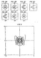
- Various ballistic patterns of fixed size can be generated by use of two of these signals, by varying the frequencies (pattern shape and density) and phase angles (pattern shape and orientation relative to the target). Such patterns would be effective against targets at a fixed range.
- FIGS. 1A through 1G the shape of the pattern, generated by two sinewave signals, one each in the X- and Y-coordinates, at the target is shown in mils for a target at 4000 feet and having a velocity of zero feet per second, using a gun system having a firing rate of 3000 shots per minute in a one second burst.
- the phase angle (X) is zero degrees.
- the phase angle (Y) varies from zero degrees in FIG. lA to 180 degrees in FIG 1G by 30 degree increments.
- FIGS. 2A through 2G the shape of the pattern, generated by two sinewave signals, one each in the X- and Y-coordinates, at the target is shown in mils for a target at 4000 feet and having a velocity of zero feet per second, using a gun system having a firing rate of 3000 shots per minute in a one second burst.
- the frequency ratio is freq (Y): freq (X) 1 hertz: 2 hertz.
- the phase angle (Y) is 45 degrees.
- the phase angle (X) varies from zero degrees in FIG. 2A to 180 degrees in FIG. 2G by 30 degree increments.
- FIGS. 3A to 3G the shape of the pattern, generated by two sinewave signals, one each in the X- and Y-coordinates, at the target is shown in mils for a target at 4000 feet and having a velocity of zero feet per second, using a gun system having a firing rate of 3000 shots per minute in a one second burst.
- the phase angle (Y) is zero degrees.
- the phase angle (X) varies from zero degrees in FIG. 3A to 180 degrees in FIG. 3G by 30 degree increments.
- Equation (1) For a single coordinate the quantity: where R is the future slant range between gun and target, V a is the target velocity, and ⁇ B0 is the inherent dispersion associated with the gun system.
- R the future slant range between gun and target
- V a the target velocity
- ⁇ B0 the inherent dispersion associated with the gun system.
- Equations (5) through (7) as well as Equations (1) through (3) must be digitized to take into account the gun cyclic rate of fire, the firing interval, the inherent ballistic dispersion, and the parameters of the harmonic signals.
- ( ⁇ ) as the reciprocal of the cyclic rate of fire in seconds and write and Then indexing on the rounds to be fired during the interval, Equations (5) through (7) respectively can be rewritten as and
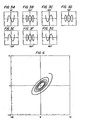
- FIG. 4 the shape of the pattern, generated by two sinewave signals, one each in the X- and Y-coordinates, at the target is shown in mils for a target initially at 4000 feet and having a velocity of 500 feet per second directly towards the gun system, using a gun system having a firing rate of 3000 shots per minute in a six second burst.
- the phase angle (Y) is zero degrees.
- the phase angle (X) thirty degrees.
- FIG. 5 the shape of the pattern, generated by two sinewave signals, one each in the X- and Y-coordinates, at the target is shown in mils for a target initially at 4000 feet having a velocity of 500 feet per second directly towards the gun system, using a gun system having a firing rate of 3000 shots per minute in a six second burst.
- the phase angle (Y) is zero degrees.
- the phase angle (X) is thirty degrees.
- FIG. 6 the shape of the pattern, generated by two sinewave signals, one each in the X- and Y-coordinates, at the target is shown in mils for a target initially at 4000 feet having a velocity of 500 feet per second directly towards the gun system, using a gun system having a firing rate of 3000 shots per minute in a six second burst.
- the phase angle (Y) is zero degrees.
- the phase angle (X) is forty-five degrees.
- the flexible gun system is firing at an aircraft target.
- the assumed desired pattern size at the target is 50 square feet when the front of the target is presented, 200 square feet when the side of the target is presented, 300 square feet when the bottom of the target is presented.
- the surface of the target ellipsoid can be characterized by the expression where X T is along an axis aligned with the target velocity vector (assumed to be out the nose of the aircraft); Y T is along an axis aligned with the target acceleration normal to the velocity vector (assumed to be out the top of the aircraft); and Z T is along an axis normal to X T and Y T (assumed to be out the right wing of the aircraft).
- a S ⁇ ab, which is the side area of 200 square feet
- a B ⁇ ac, which is the bottom area of 300 square feet
- a F ⁇ bc, which is the frontal area of 50 square feet.
- b 3.257 feet
- c is 4.886 feet
- a 19.546 feet.
- the target ellipsoid when viewed along the gun line, describes an ellipse which is the desired pattern size and shape at the target.
- the pattern size and shape relative to the flexible gun system gun line can be calculated from the target information estimated by the fire control computer in establishing the target's future position (where the projectiles fired by the gun are intended to intercept the target).
- the X T axis of the previously described target will be coincident with the gun line with the exception of adjustments made in the gun line for projectile drop due to gravity and deflection due to wind.
- the desired pattern is thus an ellipse having a major axis of 4.886 feet parallel to the horizon and a minor axis of 3.257 feet. Both of these axes are perpendicular to the gun line.
- the desired elliptical pattern can be generated at the target.
- the desired pattern is established as described in U.S. Patent 4,244,272, supra, and the application of Equation (1).
- phase angle ( E in Equation (1)) in azimuth ( ⁇ a ) and elevation ($ e ) will, in this example, differ by 90 degrees.
- the amplitude (H 0 in Equation (1)) at a range of 1500 feet will be in azimuth 4.886/1500 radians or 3.28 mils and in elevation 3.257/1500 radians or 2.17 mils.
- the flexible gun system performance characteristics place design constraints on the dispersion control system, viz., the system bandwidth, gun-order response, available power, and the system acceleration capabilities.
- the frequencies of the dispersion control sinusoidal signals approach the gun system bandwidth, there is a corresponding degradation of the system in generating the desired pattern, resulting in an attenuation of the signal amplitudes and a system-induced shift in the signal phase.
- These effects can be minimized by essentially increasing the apparent bandwidth of the flexible gun system in response to signal inputs. This is done by providing both a signal for the desired angular position and a signal for the desired angular rate to the system's servo amplifiers.
- the rate signal improves the response time of the system and provides the requisite bandwidth, while the position signal is needed primarily to eliminate errors that could increase with time if orly a rate signal is available.
- the average power to the gun system is proportional to the square of the amplitude of the sinusoidal signal and the cube of the frequency of this signal.
- the corresponding acceleration required increases linearly with the amplitude of a sinusoid and will also increase as a function of the square of the frequency.
- the limiting factor of flexible gun systems is the limit on servo motor current in keeping the gun on target. Given a well-designed system having negligible friction, a motor current limit can be expressed as an upper bound on acceleration. Thus, the limits on achievable dispersion can be expressed as a function of the amplitude and frequency of the dispersion signals.
- FIG. 7 A block diagram of the dispersion control system is shown in FIG. 7.
- the basic ballistic pattern shape is determined by the frequency and phase selected for the signals to be generated in the two principal axes, i.e., azimuth and elevation.
- the azimuth frequency (w a ) and phase (*a ) and the elevation frequency (w e ) and phase ( ⁇ e ) are inputs to a microprocessor 10.
- These four data are provided by the fire control system or by the gunner and, as previously mentioned, are a function of the slant range to the target, and the target projection on the plane normal to the line of fire.
- the basic data used to construct a sinusoidal signal and its associated derivative for each selectable frequency are stored within the microprocessor.
- the microprocessor examines the control inputs and calculates the addresses in its memory from which the sinusoid signals and derivatives must start.
- the microprocessor then cycles through the complete range of addresses as determined by the selected frequency and sequentially outputs the data from each address. This results in a quantized sinusoidal output for azimuth position and rate and elevation position and rate.
- These signals are equivalent to those obtained by sampling continuous sinusoids and quantizing the resultant to the data word length of the microprocessor.
- a sampling rate of 180 samples per second and a word length of eight bits are exemplary.
- the signals at 11, 12, 13, and 14 are eight-bit digital signals that are converted to analog voltage signals by the digital-to-analog converters, D/A, at 15, 16, 17, and 18. These D/A converters have a multiplying capability; the sinusoidal signals are multiplied by an analog signal (A a for azimuth and A e for elevation) scaled to the desired size of ballistic dispersion pattern.
- the signals at the outputs of the digital-to-analog converters are those signals corresponding to the angular position and rate in both azimuth and elevation which provide the desired pattern. These signals are applied to the control system electronics of the flexible gun system.
- the azimuth and elevation dispersion position signals, e and ⁇ , respectively, are summed by amplifiers 19 and 20 with the corresponding electrical signals for the fire control gun orders and gun position feedback signals 21 and 22 within the control system electronics.
- the outputs 21 and 22 of amplifiers 19 and 20 are thus the difference between the desired angular position of the gun and the actual position of the gun 23 and 24.
- the electronic signals 23 and 24 are obtained from potentiometers or electronic resolvers 25 and 26 whose mechanical input shaft is coupled through gears to the gun mount.
- the azimuth and elevation dispersion rate signals, and respectively, are summed by amplifiers 27 and 28 with the corresponding rate feed forward gun orders from the fire control, the tachometer (rate) feedback signals 29 and 30, and electronically filtered position error signals 31 and 32 within the control system electronics.
- the electrical signals 29 and 30 are the electrical output of tachometers 33 and 34 coupled through gears to the gun mount.
- the electrical signals 35 and 36 obtained from the outputs of amplifiers 27 and 28, respectively, are filtered and amplified by additional control system electronics 37 and 38 to produce electrical power for driving the flexible gun system motors and gun mechanical positioning mechanism 39 and 40.
- the angular rates at which the gun changes position in azimuth and elevation 41 and 42 are measured by tachometers 33 and 34.
- the angular positions of the gun in azimuth and elevation 43 and 44 which are the integral overtime of the gun angular rates, are measured by potentiometers or resolvers 25 and 26.
- the azimuth and elevation angular positions 43 and 44, respectively, of the gun follow both the gun orders generated by the sum of the fire control and dispersion control signals.
- the sequential aimpoints or gun lines generated move about the positions determined by the fire control gun orders in a path determined by the amplitude, frequency, and phase of the dispersion control sinusoidal signals.
Landscapes
- Engineering & Computer Science (AREA)
- General Engineering & Computer Science (AREA)
- Aiming, Guidance, Guns With A Light Source, Armor, Camouflage, And Targets (AREA)
Applications Claiming Priority (2)
| Application Number | Priority Date | Filing Date | Title |
|---|---|---|---|
| US06/335,436 US4464975A (en) | 1981-12-29 | 1981-12-29 | Control of dispersion of gun systems |
| US335436 | 1981-12-29 |
Publications (3)
| Publication Number | Publication Date |
|---|---|
| EP0083214A2 true EP0083214A2 (fr) | 1983-07-06 |
| EP0083214A3 EP0083214A3 (en) | 1984-08-22 |
| EP0083214B1 EP0083214B1 (fr) | 1989-05-31 |
Family
ID=23311763
Family Applications (1)
| Application Number | Title | Priority Date | Filing Date |
|---|---|---|---|
| EP82306898A Expired EP0083214B1 (fr) | 1981-12-29 | 1982-12-23 | Méthode et dispositif de contrôle de la dispersion d'un canon à haute cadence de tir |
Country Status (3)
| Country | Link |
|---|---|
| US (1) | US4464975A (fr) |
| EP (1) | EP0083214B1 (fr) |
| DE (1) | DE3279728D1 (fr) |
Cited By (1)
| Publication number | Priority date | Publication date | Assignee | Title |
|---|---|---|---|---|
| FR2569832A1 (fr) * | 1984-09-04 | 1986-03-07 | Bofors Ab | Procede d'optimisation de la couverture assuree par des armes antiaeriennes |
Families Citing this family (15)
| Publication number | Priority date | Publication date | Assignee | Title |
|---|---|---|---|---|
| US4757722A (en) * | 1986-10-27 | 1988-07-19 | Glover Marvin J | Motion conversion apparatus |
| RU2177595C2 (ru) * | 1996-11-12 | 2001-12-27 | Акционерное общество закрытого типа Научно-технический комплекс "Автоматизация и механизация технологий" | Способ поражения малоразмерных целей несколькими орудиями |
| US6014922A (en) * | 1997-12-11 | 2000-01-18 | Trw Inc. | Short range/intermediate range laser defense against chemical and biological weapons |
| RU2149339C1 (ru) * | 1999-01-22 | 2000-05-20 | Открытое акционерное общество "Специальное конструкторское бюро машиностроения" | Способ подавления танкоопасных целей, укрыто расположенных на неизвестных дальностях, автоматическим оружием боевой машины |
| RU2165581C2 (ru) * | 1999-06-07 | 2001-04-20 | Государственное унитарное предприятие "Конструкторское бюро приборостроения" | Устройство управления наводкой |
| US20040237762A1 (en) * | 1999-11-03 | 2004-12-02 | Metal Storm Limited | Set defence means |
| DK1329683T3 (da) * | 2002-01-16 | 2005-12-12 | Contraves Ag | Fremgangsmåde og apparat til kompensering af skydefejl og system-computer til våbensystem |
| RU2249779C1 (ru) * | 2003-10-13 | 2005-04-10 | Родионов Павел Владимирович | Способ стрельбы из автоматического стрелкового оружия |
| US7334466B1 (en) * | 2005-01-04 | 2008-02-26 | The United States Of America As Represented By The Secretary Of The Army | Method and apparatus for predicting and evaluating projectile performance |
| US8286872B2 (en) * | 2009-08-10 | 2012-10-16 | Kongsberg Defence & Aerospace As | Remote weapon system |
| US20110031312A1 (en) * | 2009-08-10 | 2011-02-10 | Kongsberg Defence & Aerospace As | Remote weapon system |
| ITTO20110853A1 (it) * | 2011-09-23 | 2013-03-24 | Oto Melara Spa | Postazione armata a controllo remoto, in particolare per aeromobili, come velivoli ad ala fissa |
| DE102014019199A1 (de) | 2014-12-19 | 2016-06-23 | Diehl Bgt Defence Gmbh & Co. Kg | Maschinenwaffe |
| DE102015120030A1 (de) * | 2015-09-17 | 2017-03-23 | Rheinmetall Defence Electronics Gmbh | Fernbedienbare Waffenstation und Verfahren zum Betreiben einer fernbedienbaren Waffenstation |
| DE102015119847A1 (de) * | 2015-09-18 | 2017-03-23 | Rheinmetall Defence Electronics Gmbh | Fernbedienbare Waffenstation und Verfahren zum Betreiben einer fernbedienbaren Waffenstation |
Family Cites Families (4)
| Publication number | Priority date | Publication date | Assignee | Title |
|---|---|---|---|---|
| DE684706C (de) * | 1934-07-10 | 1939-12-04 | Gustloff Werke | Von Hand einstellbare Tiefen- und Breitenstreuvorrichtung fuer M.G. -Lafetten |
| ZA72674B (en) * | 1971-02-17 | 1972-10-25 | Thomson Csf | System for aiming projectiles at close range |
| US3848509A (en) * | 1972-10-31 | 1974-11-19 | Us Navy | Closed-loop gun control system |
| US4244272A (en) * | 1978-10-10 | 1981-01-13 | General Electric Company | Dispersion-controlled multibarrel gun system |
-
1981
- 1981-12-29 US US06/335,436 patent/US4464975A/en not_active Expired - Lifetime
-
1982
- 1982-12-23 DE DE8282306898T patent/DE3279728D1/de not_active Expired
- 1982-12-23 EP EP82306898A patent/EP0083214B1/fr not_active Expired
Cited By (1)
| Publication number | Priority date | Publication date | Assignee | Title |
|---|---|---|---|---|
| FR2569832A1 (fr) * | 1984-09-04 | 1986-03-07 | Bofors Ab | Procede d'optimisation de la couverture assuree par des armes antiaeriennes |
Also Published As
| Publication number | Publication date |
|---|---|
| US4464975A (en) | 1984-08-14 |
| DE3279728D1 (en) | 1989-07-06 |
| EP0083214A3 (en) | 1984-08-22 |
| EP0083214B1 (fr) | 1989-05-31 |
Similar Documents
| Publication | Publication Date | Title |
|---|---|---|
| EP0083214B1 (fr) | Méthode et dispositif de contrôle de la dispersion d'un canon à haute cadence de tir | |
| US4004729A (en) | Automated fire control apparatus | |
| US4347996A (en) | Spin-stabilized projectile and guidance system therefor | |
| US3995792A (en) | Laser missile guidance system | |
| CA1183589A (fr) | Methode et materiel de controle de la visee et du tir sur cible reelle | |
| US4020324A (en) | Weapon delivery system | |
| US3882496A (en) | Non-destructive weapon system evaluation apparatus and method for using same | |
| US4020407A (en) | Control system for tracking a moving target | |
| US4244272A (en) | Dispersion-controlled multibarrel gun system | |
| US3900175A (en) | Guidance system for an anti-aircraft missile | |
| US4038521A (en) | Aiming device for firing on movable targets | |
| GB2251834A (en) | Guided missiles and like devices | |
| US4898340A (en) | Apparatus and method for controlling a cannon-launched projectile | |
| JP4846102B2 (ja) | 装置間の照準誤差を補正するための方法及び装置 | |
| RU2219483C2 (ru) | Способ стрельбы управляемым снарядом и система наведения управляемого снаряда | |
| EP1264154B1 (fr) | Technique de commande balistique de tir et dispositif pour projectile tournant ou stabilise par ailettes | |
| GB2095799A (en) | An aiming device for use in firing at moving targets | |
| EP0418062B1 (fr) | Viseur calculant la direction | |
| US3371887A (en) | Apparatus and method for guiding a first travelling body relative to a second travelling body | |
| CN211977703U (zh) | 一种武器火炮控制系统 | |
| RU2818701C1 (ru) | Способ управления полетом реактивных снарядов и система для его осуществления | |
| RU2814323C1 (ru) | Способ управления полетом реактивных снарядов и система для его осуществления | |
| KR810001061B1 (ko) | 자동사격관제장치 | |
| GB2030686A (en) | Weapon training systems | |
| US2782988A (en) | Computing gun sight |
Legal Events
| Date | Code | Title | Description |
|---|---|---|---|
| PUAI | Public reference made under article 153(3) epc to a published international application that has entered the european phase |
Free format text: ORIGINAL CODE: 0009012 |
|
| AK | Designated contracting states |
Designated state(s): CH DE FR GB IT LI |
|
| PUAL | Search report despatched |
Free format text: ORIGINAL CODE: 0009013 |
|
| AK | Designated contracting states |
Designated state(s): CH DE FR GB IT LI |
|
| 17P | Request for examination filed |
Effective date: 19850102 |
|
| 17Q | First examination report despatched |
Effective date: 19860718 |
|
| R17C | First examination report despatched (corrected) |
Effective date: 19870611 |
|
| GRAA | (expected) grant |
Free format text: ORIGINAL CODE: 0009210 |
|
| AK | Designated contracting states |
Kind code of ref document: B1 Designated state(s): CH DE FR GB IT LI |
|
| REF | Corresponds to: |
Ref document number: 3279728 Country of ref document: DE Date of ref document: 19890706 |
|
| ET | Fr: translation filed | ||
| ITF | It: translation for a ep patent filed | ||
| PLBE | No opposition filed within time limit |
Free format text: ORIGINAL CODE: 0009261 |
|
| STAA | Information on the status of an ep patent application or granted ep patent |
Free format text: STATUS: NO OPPOSITION FILED WITHIN TIME LIMIT |
|
| 26N | No opposition filed | ||
| ITTA | It: last paid annual fee | ||
| PGFP | Annual fee paid to national office [announced via postgrant information from national office to epo] |
Ref country code: FR Payment date: 19941112 Year of fee payment: 13 |
|
| PGFP | Annual fee paid to national office [announced via postgrant information from national office to epo] |
Ref country code: CH Payment date: 19941114 Year of fee payment: 13 |
|
| PGFP | Annual fee paid to national office [announced via postgrant information from national office to epo] |
Ref country code: DE Payment date: 19941125 Year of fee payment: 13 |
|
| PGFP | Annual fee paid to national office [announced via postgrant information from national office to epo] |
Ref country code: GB Payment date: 19941129 Year of fee payment: 13 |
|
| PG25 | Lapsed in a contracting state [announced via postgrant information from national office to epo] |
Ref country code: GB Effective date: 19951223 |
|
| PG25 | Lapsed in a contracting state [announced via postgrant information from national office to epo] |
Ref country code: LI Effective date: 19951231 Ref country code: CH Effective date: 19951231 |
|
| GBPC | Gb: european patent ceased through non-payment of renewal fee |
Effective date: 19951223 |
|
| REG | Reference to a national code |
Ref country code: CH Ref legal event code: PL |
|
| PG25 | Lapsed in a contracting state [announced via postgrant information from national office to epo] |
Ref country code: FR Effective date: 19960830 |
|
| PG25 | Lapsed in a contracting state [announced via postgrant information from national office to epo] |
Ref country code: DE Effective date: 19960903 |
|
| REG | Reference to a national code |
Ref country code: FR Ref legal event code: ST |