EP0083251B1 - Tube de sortie de fil d'une unité de filature à bout libéré - Google Patents
Tube de sortie de fil d'une unité de filature à bout libéré Download PDFInfo
- Publication number
- EP0083251B1 EP0083251B1 EP82307010A EP82307010A EP0083251B1 EP 0083251 B1 EP0083251 B1 EP 0083251B1 EP 82307010 A EP82307010 A EP 82307010A EP 82307010 A EP82307010 A EP 82307010A EP 0083251 B1 EP0083251 B1 EP 0083251B1
- Authority
- EP
- European Patent Office
- Prior art keywords
- yarn
- tube
- draw
- twist
- inlet
- Prior art date
- Legal status (The legal status is an assumption and is not a legal conclusion. Google has not performed a legal analysis and makes no representation as to the accuracy of the status listed.)
- Expired
Links
- 238000007383 open-end spinning Methods 0.000 title claims description 9
- 238000009987 spinning Methods 0.000 description 17
- 230000005540 biological transmission Effects 0.000 description 12
- 239000000835 fiber Substances 0.000 description 7
- 238000004804 winding Methods 0.000 description 4
- 229920000742 Cotton Polymers 0.000 description 2
- 230000000694 effects Effects 0.000 description 1
- 229920000728 polyester Polymers 0.000 description 1
- 238000011144 upstream manufacturing Methods 0.000 description 1
Images


Classifications
-
- D—TEXTILES; PAPER
- D01—NATURAL OR MAN-MADE THREADS OR FIBRES; SPINNING
- D01H—SPINNING OR TWISTING
- D01H4/00—Open-end spinning machines or arrangements for imparting twist to independently moving fibres separated from slivers; Piecing arrangements therefor; Covering endless core threads with fibres by open-end spinning techniques
- D01H4/04—Open-end spinning machines or arrangements for imparting twist to independently moving fibres separated from slivers; Piecing arrangements therefor; Covering endless core threads with fibres by open-end spinning techniques imparting twist by contact of fibres with a running surface
- D01H4/08—Rotor spinning, i.e. the running surface being provided by a rotor
- D01H4/10—Rotors
-
- D—TEXTILES; PAPER
- D01—NATURAL OR MAN-MADE THREADS OR FIBRES; SPINNING
- D01H—SPINNING OR TWISTING
- D01H4/00—Open-end spinning machines or arrangements for imparting twist to independently moving fibres separated from slivers; Piecing arrangements therefor; Covering endless core threads with fibres by open-end spinning techniques
- D01H4/40—Removing running yarn from the yarn forming region, e.g. using tubes
Definitions
- This invention relates to a yarn draw off tube for an open-end spinning unit.
- the yarn draw off tube for an open-end spinning unit which can satisfactorily transmit a twist to the root portion of a yarn during the spinning operation and which can produce a soft twist yarn having few fluffs and a good evenness.
- the yarn draw off tube according to the present invention has a yarn inlet eccentric from the center axis of the tube at a specific distance as well as deviating in a specific direction relative to the yarn outlet.
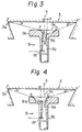
- an open-end spinning unit 1 comprises a spinning rotor 3 rotatably supported on a stationary part by a bearing 5 and driven by a belt 7 and a yarn draw off tube 9 fixedly secured to an outer wall of a housing 11 so as to confront the spinning rotor 3.
- the housing 11 is provided therein with a feed roller 13 for introducing a sliver S into the housing, a presser 15 urged onto the surface of the feed roller 13, a combing roller 17 for opening the sliver S to individual fibers, and a fiber-transporting duct 19 for conveying the individual fibers, along with an airstream, into the spinning rotor 3.
- the yarn draw off tube 9, illustrated in Fig. 2 consists of a disc portion 9a and a tube portion 9b extending from the center of the disc portion 9a.
- the disc portion 9a has a circular yarn inlet 9c eccentric from an axis X of the tube portion 9b.
- the tube portion 9b has a guide channel 9g extending through its body along the axis X.
- the guide channel 9g widens towards the bottom of the tube portion 9b and is connected to the yarn inlet 9c through an aperture 9d at the top of the tube portion 9b.
- On a side wall of the guide channel 9g is provided a yarn outlet 9f. In this connection, the center of the yarn inlet 9c deviates opposite to the yarn outlet 9f relative to the axis X (refer to Fig. 3).
- Fig. 3 shows the yarn paths as chain lines extending from a fiber-collecting surface 3a of the spinning rotor 3 to the yarn outlet 9f of the yarn draw off tube 9 through the yarn inlet 9c.
- One twist is imparted to a yarn portion existing between point F or F' on the fiber-collecting surface 3a and point A in the outlet 9f by one revolution of the rotor 3 about the axis X.
- the twisting occurs at first at point A, farthest from the rotor along the axis X, and the twist is transmitted sequentially upstream along the yarn and finally reaches point F or F'. If the yarn contacts the surface of other objects in the midportion of the yarn path, the twist transmission is more or less disturbed.
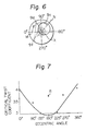
- the eccentric angle 8 shown in Fig. 6 is an angle between the axis M of the yarn outlet 9f (the axis M corresponds to a 0°-180° line) and the diameter N of the yarn inlet 9c passing through the axis X of the tube portion 9b.
- the eccentric angle is measured in a clockwise direction from the axis M.
- the yarn draw off tube shown in Fig. 3 has an eccentric angle of 180°, that is the yarn inlet 9c deviates in a direction opposite to that of the yarn outlet 9f relative to the axis X, as is shown in Fig. 5a.
- the mean yarn path passes through points A, B, E, and F of Fig. 3, where A is a point at the yarn outlet 9f, B and C are points on the bottom edge of the yarn inlet 9c; and D and E are points on the top edge of the yarn outlet 9c. Since the yarn contacts the surface of the yarn draw off tube 9 at AB and BE, and, further, since the tangential angle a at E relatively small, a twist cannot be smoothly transmitted from A to F. Rather, it accumulates mainly in the portion between A and B.
- the mean yarn path passes through the points A, C, D and F' of Fig. 3. Since the surface-contact of the yarn is less than that in the area from 270° to 90° and the tangential angle ⁇ at D is relatively large, a twist can be easily transmitted from A to F'. Thus, in the latter area, the accumulated twist in the preceding area and the newly generated twist are simultaneously discharged toward F'. In other words, in the case of the yarn draw off tube of Fig. 5a, the twist is discharged and transmitted smoothly within a half path per one rotation of the spinning rotor.
- the yarn inlet 9c deviates in the same direction as the yarn outlet 9f relative to the axis X, as shown in Fig. 5b.
- the yarn contacts the surface of the guide channel 9g at AB, and, as a result, a twist cannot be transmitted from A to F.
- the yarn contacts the wall of the yarn inlet 9c at CD, resulting in a poor twist transmission.
- the twist imparted to the yarn portion at A cannot ascend smoothly toward F or F' in one rotation and instead accumulates in the yarn portion between A and B until the torque of the yarn portion overcomes the frictional resistance of the yarn path.
- the twist distribution along the produced yarn becomes uneven, resulting in yarn breakage and yarn of poor quality.
- Table 1 The above-mentioned analysis is summarized in Table 1.
- O and X represent good twist transmission and poor twist transmission, respectively.
- the yarn draw off tube having a yarn inlet deviating just opposite to the yarn outlet i.e., a yarn inlet having an eccentric angle of 180°, has the widest area for good twist transmission during each revolution of the spinning rotor.
- the eccentric radius e of the yarn inlet 9c also has an effect on twist transmission (refer to Fig. 3).
- the present inventors performed an experiment in an attempt to discover the optimum range of the eccentric radius e. Five runs were carried out in the experiment, in which a 32'° (cotton counts) yarn was spun from a sliver composed of 30% polyester staple fibers having a fineness of 1.3 denier and a length of 35 mm and 70% of cotton by means of five spinning units, each of which had the yarn draw off tube shown in Fig. 5a. All of the tubes were the same size except for the eccentric radius e.
- the other test conditions were as follows:
- the resultant yarns were measured with regard to:
- the eccentricity e/d is preferably within a range of from 1/3 to 1.
- the inventors performed another spinning experiment to confirm the results shown in Table 1 and to determine the preferred range of the eccentric angle.
- the experimental conditions were as follows:
- the results are represented by dots in the graph of Fig. 7.
- the dot R represents, for the purpose of comparison, a value of a conventional yarn draw off tube having a non-eccentric yarn inlet.
- ⁇ c is the smallest at an eccentric angle of 180° and increases as it becomes more distant from this point.
- the preferable range of the eccentric angle is from 135° to 225°.
- the spinnability of an open-end spinning unit is improved remarkably, and a yarn excellent in strength, as well as in appearance, can be obtained.
Landscapes
- Engineering & Computer Science (AREA)
- Mechanical Engineering (AREA)
- Textile Engineering (AREA)
- Spinning Or Twisting Of Yarns (AREA)
Claims (4)
Applications Claiming Priority (2)
| Application Number | Priority Date | Filing Date | Title |
|---|---|---|---|
| JP214821/81 | 1981-12-29 | ||
| JP56214821A JPS58120825A (ja) | 1981-12-29 | 1981-12-29 | オ−プンエンド精紡機の糸引出装置 |
Publications (3)
| Publication Number | Publication Date |
|---|---|
| EP0083251A2 EP0083251A2 (fr) | 1983-07-06 |
| EP0083251A3 EP0083251A3 (en) | 1984-08-01 |
| EP0083251B1 true EP0083251B1 (fr) | 1986-05-28 |
Family
ID=16662078
Family Applications (1)
| Application Number | Title | Priority Date | Filing Date |
|---|---|---|---|
| EP82307010A Expired EP0083251B1 (fr) | 1981-12-29 | 1982-12-30 | Tube de sortie de fil d'une unité de filature à bout libéré |
Country Status (5)
| Country | Link |
|---|---|
| US (1) | US4481766A (fr) |
| EP (1) | EP0083251B1 (fr) |
| JP (1) | JPS58120825A (fr) |
| KR (1) | KR850000724B1 (fr) |
| DE (1) | DE3271485D1 (fr) |
Families Citing this family (8)
| Publication number | Priority date | Publication date | Assignee | Title |
|---|---|---|---|---|
| CH672800A5 (fr) * | 1986-03-19 | 1989-12-29 | Schlafhorst & Co W | |
| DE3634567A1 (de) * | 1986-04-04 | 1987-10-08 | Joachim Prof Dr Luenenschloss | Verfahren und vorrichtung zum abziehen des garns aus der fasersammelrille des rotors einer offenend-rotor-spinnvorrichtung |
| DE3640217A1 (de) * | 1986-11-25 | 1988-05-26 | Fritz Stahlecker | Oe-rotorspinnmaschine |
| DE3705479A1 (de) * | 1987-02-20 | 1988-09-01 | Schlafhorst & Co W | Verfahren und vorrichtung zum verbessern eines in dem rotor einer offenend-spinnvorrichtung erzeugten garns |
| US5193332A (en) * | 1989-07-04 | 1993-03-16 | Albert Kriegler | Spinning or twisting device with a pipe shaped element capable of being subjected to negative pressure |
| US5437147A (en) * | 1992-08-20 | 1995-08-01 | Burckhardt America, Inc. | Open end spinning device |
| GB2274659A (en) * | 1993-01-29 | 1994-08-03 | Ka King Wu | Rotor for open end spinning |
| CN103343408B (zh) * | 2013-07-05 | 2016-01-20 | 宜宾纬络纺织有限公司 | 转杯纺纱加捻工艺 |
Family Cites Families (10)
| Publication number | Priority date | Publication date | Assignee | Title |
|---|---|---|---|---|
| FR1476970A (fr) * | 1965-12-01 | 1967-04-14 | Vyzk Ustav Bavlnarsky | Dispositif pour la filature continue sans boucle de fibres textiles à l'aide d'une chambre de filature rotative |
| AT264335B (de) * | 1965-12-01 | 1968-08-26 | Vyzk Ustav Bavlnarsky | Spinnkammer-Spinnvorrichtung |
| DE1535014C3 (de) * | 1965-12-07 | 1974-10-03 | Vyzk Ustav Bavlnarsky | Offen-End-Spinnvorrichtung |
| FR1483046A (fr) * | 1965-12-07 | 1967-06-02 | Vyzk Ustav Bavlnarsky | Mécanisme d'extraction du fil d'un dispositif destiné à la filature continue sans anneau de fibres textiles |
| FR1544569A (fr) * | 1966-11-17 | 1968-10-31 | Schubert & Salzer Maschinen | Procédé et dispositif pour le filage d'un ruban de fibres |
| DE2130724C3 (de) * | 1971-06-21 | 1978-06-08 | Skf Kugellagerfabriken Gmbh, 8720 Schweinfurt | Fadenabzugskanal an einer Offenend-Spinnvorrichtung |
| DE2130722B2 (de) * | 1971-06-21 | 1976-04-15 | Skf Kugellagerfabriken Gmbh, 8720 Schweinfurt | Vorrichtung zum offenend-spinnen von textilfasern |
| CS165068B1 (fr) * | 1972-10-16 | 1975-11-28 | ||
| JPS49132329A (fr) * | 1973-04-21 | 1974-12-19 | ||
| JPS5434038Y2 (fr) * | 1973-10-31 | 1979-10-19 |
-
1981
- 1981-12-29 JP JP56214821A patent/JPS58120825A/ja active Granted
-
1982
- 1982-12-21 KR KR8205723A patent/KR850000724B1/ko not_active Expired
- 1982-12-29 US US06/454,181 patent/US4481766A/en not_active Expired - Lifetime
- 1982-12-30 EP EP82307010A patent/EP0083251B1/fr not_active Expired
- 1982-12-30 DE DE8282307010T patent/DE3271485D1/de not_active Expired
Also Published As
| Publication number | Publication date |
|---|---|
| EP0083251A3 (en) | 1984-08-01 |
| JPS58120825A (ja) | 1983-07-18 |
| DE3271485D1 (en) | 1986-07-03 |
| EP0083251A2 (fr) | 1983-07-06 |
| JPS613895B2 (fr) | 1986-02-05 |
| KR840002922A (ko) | 1984-07-21 |
| US4481766A (en) | 1984-11-13 |
| KR850000724B1 (ko) | 1985-05-23 |
Similar Documents
| Publication | Publication Date | Title |
|---|---|---|
| EP0031250B1 (fr) | Fil composite | |
| US4845932A (en) | Method of and apparatus for spinning yarn | |
| CA1092452A (fr) | File multicomposant, sa methode et son materiel de fabrication | |
| EP0083251B1 (fr) | Tube de sortie de fil d'une unité de filature à bout libéré | |
| US4241571A (en) | Apparatus for open-end or round-about spinning of a thread | |
| US3965661A (en) | Thread drawoff tube for an open-end spinning unit | |
| US4302926A (en) | Multi-component yarn and method of apparatus for its manufacture | |
| EP0057876B1 (fr) | Dispositif de torsion et de filature par voie pneumatique | |
| US4068456A (en) | Open-end spinning device | |
| GB2151265A (en) | Drafting method and apparatus in spinning machine | |
| US4642981A (en) | Rotor with yarn guide for open-end spinning | |
| US5675965A (en) | Navel member for open end spinning device | |
| EP0301581B1 (fr) | Unité de filage d'un métier à filer à bout libre | |
| US4479348A (en) | Apparatus for spinning fasciated yarn | |
| CN1035143A (zh) | 一种用于自由端纺纱的方法及装置 | |
| US4476672A (en) | Air nozzle for fasciated yarn spinning | |
| US3786622A (en) | Yarn spinning method and apparatus therefor | |
| US3696604A (en) | Centrifugal spinning device | |
| US4593522A (en) | Method and apparatus for producing spun yarn | |
| RU2057824C1 (ru) | Полуфабрикат для прядильного производства, способ его получения и устройство для его осуществления | |
| JPS6018338B2 (ja) | ノズル | |
| GB2041019A (en) | Open End Spinning of Composite Yarn | |
| JPS607730B2 (ja) | ロ−タ式オ−プンエンド精紡機 | |
| JPS6235033Y2 (fr) | ||
| US4938018A (en) | Friction spinning machine |
Legal Events
| Date | Code | Title | Description |
|---|---|---|---|
| PUAI | Public reference made under article 153(3) epc to a published international application that has entered the european phase |
Free format text: ORIGINAL CODE: 0009012 |
|
| AK | Designated contracting states |
Designated state(s): CH DE GB LI |
|
| PUAL | Search report despatched |
Free format text: ORIGINAL CODE: 0009013 |
|
| AK | Designated contracting states |
Designated state(s): CH DE GB LI |
|
| 17P | Request for examination filed |
Effective date: 19840910 |
|
| GRAA | (expected) grant |
Free format text: ORIGINAL CODE: 0009210 |
|
| AK | Designated contracting states |
Kind code of ref document: B1 Designated state(s): CH DE GB LI |
|
| REF | Corresponds to: |
Ref document number: 3271485 Country of ref document: DE Date of ref document: 19860703 |
|
| PLBE | No opposition filed within time limit |
Free format text: ORIGINAL CODE: 0009261 |
|
| STAA | Information on the status of an ep patent application or granted ep patent |
Free format text: STATUS: NO OPPOSITION FILED WITHIN TIME LIMIT |
|
| 26N | No opposition filed | ||
| PGFP | Annual fee paid to national office [announced via postgrant information from national office to epo] |
Ref country code: GB Payment date: 19891130 Year of fee payment: 8 |
|
| PG25 | Lapsed in a contracting state [announced via postgrant information from national office to epo] |
Ref country code: GB Effective date: 19901230 |
|
| GBPC | Gb: european patent ceased through non-payment of renewal fee | ||
| PGFP | Annual fee paid to national office [announced via postgrant information from national office to epo] |
Ref country code: CH Payment date: 19961224 Year of fee payment: 15 |
|
| PGFP | Annual fee paid to national office [announced via postgrant information from national office to epo] |
Ref country code: DE Payment date: 19970124 Year of fee payment: 15 |
|
| PG25 | Lapsed in a contracting state [announced via postgrant information from national office to epo] |
Ref country code: LI Free format text: LAPSE BECAUSE OF NON-PAYMENT OF DUE FEES Effective date: 19971231 Ref country code: CH Free format text: LAPSE BECAUSE OF NON-PAYMENT OF DUE FEES Effective date: 19971231 |
|
| REG | Reference to a national code |
Ref country code: CH Ref legal event code: PL |
|
| PG25 | Lapsed in a contracting state [announced via postgrant information from national office to epo] |
Ref country code: DE Free format text: LAPSE BECAUSE OF NON-PAYMENT OF DUE FEES Effective date: 19980901 |