EP0083330A2 - Accumulateur acide de plomb à connexion en fond de bac - Google Patents
Accumulateur acide de plomb à connexion en fond de bac Download PDFInfo
- Publication number
- EP0083330A2 EP0083330A2 EP82850265A EP82850265A EP0083330A2 EP 0083330 A2 EP0083330 A2 EP 0083330A2 EP 82850265 A EP82850265 A EP 82850265A EP 82850265 A EP82850265 A EP 82850265A EP 0083330 A2 EP0083330 A2 EP 0083330A2
- Authority
- EP
- European Patent Office
- Prior art keywords
- cell
- cells
- connection
- cover
- partition wall
- Prior art date
- Legal status (The legal status is an assumption and is not a legal conclusion. Google has not performed a legal analysis and makes no representation as to the accuracy of the status listed.)
- Granted
Links
Images

Classifications
-
- H—ELECTRICITY
- H01—ELECTRIC ELEMENTS
- H01M—PROCESSES OR MEANS, e.g. BATTERIES, FOR THE DIRECT CONVERSION OF CHEMICAL ENERGY INTO ELECTRICAL ENERGY
- H01M10/00—Secondary cells; Manufacture thereof
- H01M10/06—Lead-acid accumulators
- H01M10/12—Construction or manufacture
-
- H—ELECTRICITY
- H01—ELECTRIC ELEMENTS
- H01M—PROCESSES OR MEANS, e.g. BATTERIES, FOR THE DIRECT CONVERSION OF CHEMICAL ENERGY INTO ELECTRICAL ENERGY
- H01M10/00—Secondary cells; Manufacture thereof
- H01M10/06—Lead-acid accumulators
- H01M10/12—Construction or manufacture
- H01M10/16—Suspending or supporting electrodes or groups of electrodes in the case
-
- H—ELECTRICITY
- H01—ELECTRIC ELEMENTS
- H01M—PROCESSES OR MEANS, e.g. BATTERIES, FOR THE DIRECT CONVERSION OF CHEMICAL ENERGY INTO ELECTRICAL ENERGY
- H01M50/00—Constructional details or processes of manufacture of the non-active parts of electrochemical cells other than fuel cells, e.g. hybrid cells
- H01M50/50—Current conducting connections for cells or batteries
- H01M50/528—Fixed electrical connections, i.e. not intended for disconnection
- H01M50/529—Intercell connections through partitions, e.g. in a battery casing
-
- Y—GENERAL TAGGING OF NEW TECHNOLOGICAL DEVELOPMENTS; GENERAL TAGGING OF CROSS-SECTIONAL TECHNOLOGIES SPANNING OVER SEVERAL SECTIONS OF THE IPC; TECHNICAL SUBJECTS COVERED BY FORMER USPC CROSS-REFERENCE ART COLLECTIONS [XRACs] AND DIGESTS
- Y02—TECHNOLOGIES OR APPLICATIONS FOR MITIGATION OR ADAPTATION AGAINST CLIMATE CHANGE
- Y02E—REDUCTION OF GREENHOUSE GAS [GHG] EMISSIONS, RELATED TO ENERGY GENERATION, TRANSMISSION OR DISTRIBUTION
- Y02E60/00—Enabling technologies; Technologies with a potential or indirect contribution to GHG emissions mitigation
- Y02E60/10—Energy storage using batteries
-
- Y—GENERAL TAGGING OF NEW TECHNOLOGICAL DEVELOPMENTS; GENERAL TAGGING OF CROSS-SECTIONAL TECHNOLOGIES SPANNING OVER SEVERAL SECTIONS OF THE IPC; TECHNICAL SUBJECTS COVERED BY FORMER USPC CROSS-REFERENCE ART COLLECTIONS [XRACs] AND DIGESTS
- Y02—TECHNOLOGIES OR APPLICATIONS FOR MITIGATION OR ADAPTATION AGAINST CLIMATE CHANGE
- Y02P—CLIMATE CHANGE MITIGATION TECHNOLOGIES IN THE PRODUCTION OR PROCESSING OF GOODS
- Y02P70/00—Climate change mitigation technologies in the production process for final industrial or consumer products
- Y02P70/50—Manufacturing or production processes characterised by the final manufactured product
Definitions
- the present invention relates to a lead acid accumulator with bottom connection, comprising at least one pair of accumulator cells, each cell being enclosed in a cell vessel which is common to said pair of cells and has a liquid-tight partition wall between the separate cells and a cover with bores for the pole posts, each of said cells containing two groups of electrode plates, one positive and one negative which are connected to corresponding connection straps, one of which is situated above and the other below the electrode plates, the bottom connection strap being common to said pair of cells and passing from one cell to the other through the partition wall.
- Lead acid accumulators with bottom connections of the kind described above are previously known, e.g. through FR-PS 859 040.
- This arrangement offers the advantage that each cell is provided with only one upwardly extending pole post which is passed through,the cover.
- the electrical connection between the cells is located at the bottom, below the electrode plates in such a way that the bottom connection strap will be common to the pair of cells and is consequently positive in one cell and negative in the other. Since soldered connections as well as screw connections may be avoided with such a bottom connection, the transition resistance between the cells will be neglibible. This is of particular importance in accumulators such as are used in submarines and where the cell height is large relative to the bottom area.
- the conductive resistance will be relatively high if the batteries are designed in a conventional manner, i.e. that the cell connection is located at the top of the battery.
- the arrangement with the bottom connection will consequently eliminate the need for the second pole post in the cover which means that the battery will also be much lighter compared to one of conventional design.
- the current distribution in a battery with bottom connection will also be more uniform during charging and discharging sequences, compared to an accumulator of conventional design.
- the more uniform current distribution will also permit more rapid charging and longer life of the electrode plates.
- the object of the present invention is to improve the mechanical properties of the battery, such as the capability of withstanding external shock stresses without jeopardizing the function of the battery or deteriorating its electrical properties. This is particularly important for batteries intended for use on board submarines.
- connection straps in each cell are disposed substantially mutually in parallel and are located in a plane which mainly goes through the centre axes of the connection straps and through the centres of gravity of the electrode plates, and in that the upper connection strap in each cell is connected to the cover by means of one or several pole posts which are substantially located in the plane through the centre axes of the connection straps, and that the lower common connection strap is supported by at least two shock-absorbing elements arranged on either side of the partition wall.
- pole posts are fixed to the cover by means of a mechanical connection which prevents axial displacement in the bores through the cover.
- the invention offers the possibility of utilizing the cover as a schock- absorbing element for the group of electrode plates which is connected to the upper connection strap.
- the cover is preferably made of glass fibre reinforced plastics and the shock-absorbing element of rubber.
- the invention also provides a structure in which the groups of electrode plates will be given a maximum flexible extension for a given external dimension of the accumulator cell without reducing the volume for active material. Since the electrode plates in this structure are symmetrically supported at the bottom of the cell and in a similar way are symmetrically suspended by the upper connection the moment arms will be minimized for the forces affecting the electrode plates when the battery is subject to shocks.
- the long elastic extension for the electrode plate groups will make possible maximum utilization of the electrolyte for absorbing the shock energy when the plate groups move in the liquid relative to the cell vessel.
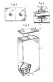
- the lead acid accumulator 1 of the invention comprises two pairs of electrolyte cells 2 and 7 which are enclosed in a cell vessel 4 with a partition wall 5 between the separate cells and with a cover 6 which is provided with springs 7 and 8 (see Fig. 6) for the pole posts 9 and 10 passing through the cover 6 and rigidly connected thereto.
- Each cell comprises at least one positive 11 or 12 and one negative 13 or 14 group of electrodes which are connected to the respective connection straps.
- the positive electrode 11 is connected to the upper connection strap 15, whereas the two negative electrodes 13 are connected to the lower strap 16.
- connection strap 17 In the cell 3 to the left in the Figure, the conditions are the opposite, the two negative electrodes 14 being connected to the upper connection strap 17, and the positive electrode 12 being connected to the connection strap 16 which is common to the two cells.
- the two pole posts 9 and 10 extending through the cover will thus form the output terminals for a positive cell 2 and a negative cell 3, respectively.
- the pole posts are moreover provided with tapered collars 18 and 19, (see Fig. 2) which bear against the interior surface of the cover 6, while the threaded portions 20 and 21, of the posts extend outwardly from the springs 7 and 8 in the cover 6, to which the posts are connected by means of threaded nuts 22 and 23.
- the lower connection strap 16 is supported on rubber members 24 and 25 which support the electrode groups 12 and 13, in each of the cells, while the posts 9 and 10, which are rigidly connected to the cover 6, will suspend the other electrode groups 14 and 11, via the upper connection strap 15 and 17.
- FIGs. 2-5 The arrangement with the different components included in the battery structure according to the invention are more clearly shown on Figs. 2-5.
- Each cell is thus enclosed in a liquid-tight cover 26 and 27, and the lower connection strap 16, which is common to the two cells, is passed through the partition wall 15 and through the two liquid-tight casings 26 and 27 by means of a bushing 28 which is shown in detail on Fig. 5.
- the two connection straps 15, 16 and 17, 16, in the cells 2 and 3 respectively are disposed substantially mutually in parallel, and are located in a plane 29 essentially going through the centre axes 30, 31 of the connection straps and through the centres of gravity 32 of the electrode plates.
- This plane 29 forms a vertical plane through the gravitational line of action of the electrode plates, connection straps and the pole posts when the battery is supported on a horizontal surface.
- the electrode plates will be subject to a maximum moment around their suspension points when exposed to a shock load in the vertical plane this moment being as small as possible.
- the bottom and the cover of the cell vessel will consequently only be exposed to compressive forces and when subject to a shock load the cover 6 and the rubber members 24 and 25 will be deformed in the way indicated with dashed lines on Fig. 3.
- the resilient properties of the cover 6 can be utilized to a maximum, which means that a certain elastic deflection will result in the least possible stress on the cover 6 and on the cell vessel 4.
- the lower connection strap 16 is supported by the rubber members 24 and 25 which are symmetrically located on the bottom of their corresponding cell.
- the cover and the rubber members will consequently cooperate to provide a low frequency suspension with long elastic extension for the electrode groups, and with the effect of the electrolyte these deflection lengths will give the accumulator high inner damping and consequently the ability to absorb shock energy.
- the bottom of the cell vessel could thus be subject to high shock loads without risk of damaging the active portions of the cell.
- the high inner damping will also have the advantage of giving the battery a low rebound amplitude.
- the accumulator does not need to be fixed to the bed, which is usual in the installation of conventional batteries.
- An accumulator according to the invention can consequently be put directly on the support surface without being fixed and the space above the battery can be adapted to the characteristic low rebound amplitude.
- the battery bed will not have to be supplied with special shock-absorbing means. All these characteristics taken together mean that it will be possible to install a greater battery volume in a given space, if the battery is designed according to the invention, compared to the volume which could be installed if the battery is of conventional design.
- Fig. 5 shows in detail the bushing 28 through the partition wall 5 and the two liquid-tight casings 26 and 27 which are provided with tubular, mutually opposing openings 33 and 34 in overlapping relation around the lower connection strap 16.
- Two hose clips 35 and 36 are arranged around the outer tubular opening 34 in order to effectively prevent leakage of electrolyte into the cell vessel between the two liquid-tight casings.
- the bushing 28 in the partition wall 5 is thus flexible, i.e. it lacks a rigid connection with the cell vessel, making it possible for the lower connection strap to move relative the vessel without causing any damage. This is of course of greatest importance when the accumulator is subject to shock loads.
- Fig. 6 shows the cell vessel 4 and the cover 6 with the two bores 7 and 8 for the pole posts 20 and 21.
- the Figure clearly illustrates the central and symmetrical location of one rubber member 25 in the negative cell 3. It also illustrates that the partition wall 5 is provided with a groove 37 from the top of the vessel and down to the bottom 38 thereof, to permit the two interconnected cells 2 and 3 to be lowered into the vessel until they rest against the rubber members 24 and 25.
- the cell vessel is suitably made of glass fiber-reinforced plastics, and the two liquid-tight casings are suitably made of rubber.
Landscapes
- Engineering & Computer Science (AREA)
- Manufacturing & Machinery (AREA)
- Chemical & Material Sciences (AREA)
- Chemical Kinetics & Catalysis (AREA)
- Electrochemistry (AREA)
- General Chemical & Material Sciences (AREA)
- Connection Of Batteries Or Terminals (AREA)
- Lubricants (AREA)
Priority Applications (1)
| Application Number | Priority Date | Filing Date | Title |
|---|---|---|---|
| AT82850265T ATE27667T1 (de) | 1981-12-28 | 1982-12-22 | Bleisaeure akkumulator mit bodenverbindung. |
Applications Claiming Priority (2)
| Application Number | Priority Date | Filing Date | Title |
|---|---|---|---|
| SE8107784A SE445276B (sv) | 1981-12-28 | 1981-12-28 | Blyackumulator med bottenforbindning |
| SE8107784 | 1981-12-28 |
Publications (3)
| Publication Number | Publication Date |
|---|---|
| EP0083330A2 true EP0083330A2 (fr) | 1983-07-06 |
| EP0083330A3 EP0083330A3 (en) | 1984-08-22 |
| EP0083330B1 EP0083330B1 (fr) | 1987-06-03 |
Family
ID=20345374
Family Applications (1)
| Application Number | Title | Priority Date | Filing Date |
|---|---|---|---|
| EP82850265A Expired EP0083330B1 (fr) | 1981-12-28 | 1982-12-22 | Accumulateur acide de plomb à connexion en fond de bac |
Country Status (4)
| Country | Link |
|---|---|
| EP (1) | EP0083330B1 (fr) |
| AT (1) | ATE27667T1 (fr) |
| DE (1) | DE3276514D1 (fr) |
| SE (1) | SE445276B (fr) |
Cited By (6)
| Publication number | Priority date | Publication date | Assignee | Title |
|---|---|---|---|---|
| WO1999040638A1 (fr) * | 1998-02-04 | 1999-08-12 | Chloride Industrial Batteries Limited | Batterie pourvue de barrettes de connexion superieures et inferieures et de barrettes de connexion verticales supplementaires |
| EP1049185A1 (fr) * | 1999-04-30 | 2000-11-02 | Tai-Her Yang | Structure de connection entre les plaques d'électrodes et le boítier d'une batterie |
| US6555265B1 (en) | 2000-04-06 | 2003-04-29 | Hawker Energy Products, Inc. | Value regulated lead acid battery |
| WO2006133674A3 (fr) * | 2005-06-16 | 2008-03-13 | Exide Gmbh Deutsche | Pontet de connexion destine a une batterie |
| WO2014114576A1 (fr) | 2013-01-25 | 2014-07-31 | Hagemann-Systems Gmbh | Filetage et électrode de batterie ou borne de batterie dotée d'un filetage |
| CN111211359A (zh) * | 2020-01-22 | 2020-05-29 | 江西新威动力能源科技有限公司 | 蓄电池极柱上胶方法及蓄电池极柱上胶机构 |
Families Citing this family (2)
| Publication number | Priority date | Publication date | Assignee | Title |
|---|---|---|---|---|
| DE102004011270A1 (de) * | 2004-03-09 | 2005-09-29 | Deutsche Exide Standby Gmbh | Wartungsfreier Akkumulator und Verfahren zu dessen Herstellung |
| DE102006041326B3 (de) | 2006-09-01 | 2008-01-31 | Varta Automotive Systems Gmbh | Elektrische Speicherbatterie |
Family Cites Families (4)
| Publication number | Priority date | Publication date | Assignee | Title |
|---|---|---|---|---|
| US1506403A (en) * | 1923-03-28 | 1924-08-26 | Frest O Lite Company Inc | Stcrage battery |
| US2180959A (en) * | 1936-01-17 | 1939-11-21 | Prest O Lite Storage Battery C | Storage battery construction |
| FR1392265A (fr) * | 1963-05-20 | 1965-03-12 | Ford France | Accumulateur électrique |
| IT956100B (it) * | 1972-05-31 | 1973-10-10 | Alfa Romeo Spa | Telai per piastre di batterie per autoveicoli |
-
1981
- 1981-12-28 SE SE8107784A patent/SE445276B/sv not_active IP Right Cessation
-
1982
- 1982-12-22 DE DE8282850265T patent/DE3276514D1/de not_active Expired
- 1982-12-22 EP EP82850265A patent/EP0083330B1/fr not_active Expired
- 1982-12-22 AT AT82850265T patent/ATE27667T1/de not_active IP Right Cessation
Cited By (10)
| Publication number | Priority date | Publication date | Assignee | Title |
|---|---|---|---|---|
| WO1999040638A1 (fr) * | 1998-02-04 | 1999-08-12 | Chloride Industrial Batteries Limited | Batterie pourvue de barrettes de connexion superieures et inferieures et de barrettes de connexion verticales supplementaires |
| US6818345B1 (en) | 1998-02-04 | 2004-11-16 | Chloride Industrial Batteries Limited | Battery with top and bottom connecting straps and additional vertical connecting bars |
| EP1049185A1 (fr) * | 1999-04-30 | 2000-11-02 | Tai-Her Yang | Structure de connection entre les plaques d'électrodes et le boítier d'une batterie |
| US6555265B1 (en) | 2000-04-06 | 2003-04-29 | Hawker Energy Products, Inc. | Value regulated lead acid battery |
| US6815118B2 (en) | 2000-04-06 | 2004-11-09 | Hawker Energy Products, Inc. | Valve regulated lead acid battery |
| US7601456B2 (en) | 2000-04-06 | 2009-10-13 | Hawkwer Energy Products, Inc. | Valve regulated lead acid battery |
| WO2006133674A3 (fr) * | 2005-06-16 | 2008-03-13 | Exide Gmbh Deutsche | Pontet de connexion destine a une batterie |
| WO2014114576A1 (fr) | 2013-01-25 | 2014-07-31 | Hagemann-Systems Gmbh | Filetage et électrode de batterie ou borne de batterie dotée d'un filetage |
| DE102013100747A1 (de) | 2013-01-25 | 2014-07-31 | Hagemann-Systems Gmbh | Gewindeausbildung und Batterieelektrode oder Batteriepol mit Gewindeausbildung |
| CN111211359A (zh) * | 2020-01-22 | 2020-05-29 | 江西新威动力能源科技有限公司 | 蓄电池极柱上胶方法及蓄电池极柱上胶机构 |
Also Published As
| Publication number | Publication date |
|---|---|
| EP0083330B1 (fr) | 1987-06-03 |
| SE445276B (sv) | 1986-06-09 |
| ATE27667T1 (de) | 1987-06-15 |
| DE3276514D1 (en) | 1987-07-09 |
| SE8107784L (sv) | 1983-06-29 |
| EP0083330A3 (en) | 1984-08-22 |
Similar Documents
| Publication | Publication Date | Title |
|---|---|---|
| KR100226543B1 (ko) | 축전지 극판 압축 케이지 어셈블리 | |
| EP0083330B1 (fr) | Accumulateur acide de plomb à connexion en fond de bac | |
| KR940020612A (ko) | 납-산 전지 | |
| EP2381507A1 (fr) | Bloc-batteries | |
| US2515204A (en) | Storage battery plate | |
| ATE38743T1 (de) | Montage wenigstens eines zellen- oder batteriestapels. | |
| HK1005198B (en) | High capacity maintenance-free lead accumulator | |
| US5114806A (en) | Perforated retainer for horizontal mount gelled-electrolyte cells | |
| CN219534713U (zh) | 一种抗震胶体储能电池 | |
| US3846174A (en) | Proportioned current battery | |
| US3996065A (en) | Vehicle storage battery cell | |
| US1587951A (en) | Storage battery | |
| US4587181A (en) | Lead acid recombination cells | |
| EP0125904B1 (fr) | Batterie électrochimique | |
| CN114843686A (zh) | 一种适应于低温环境具有抗震动能力的锂电池 | |
| CN114050367A (zh) | 一种针对铅蓄电池的抗震组件 | |
| US2470163A (en) | Plate support for electric accumulators | |
| CN215496918U (zh) | 一种全固态锂离子电池 | |
| RU2011243C1 (ru) | Герметичная свинцово-кислотная аккумуляторная батарея | |
| CN114709537B (zh) | 一种蓄电池用固定支架和防震型铅酸蓄电池 | |
| CN211295182U (zh) | 一种内防护型铅酸蓄电池 | |
| CN217387355U (zh) | 一种电池包壳体、电池包及车辆 | |
| CN211295186U (zh) | 一种外设减震底座的铅酸蓄电池 | |
| CN217361814U (zh) | 一种软包锂电池的串并联固定板 | |
| CN217239625U (zh) | 一种锂电池防护装置 |
Legal Events
| Date | Code | Title | Description |
|---|---|---|---|
| PUAI | Public reference made under article 153(3) epc to a published international application that has entered the european phase |
Free format text: ORIGINAL CODE: 0009012 |
|
| AK | Designated contracting states |
Designated state(s): AT BE CH DE FR GB IT LI NL SE |
|
| PUAL | Search report despatched |
Free format text: ORIGINAL CODE: 0009013 |
|
| AK | Designated contracting states |
Designated state(s): AT BE CH DE FR GB IT LI NL SE |
|
| 17P | Request for examination filed |
Effective date: 19850118 |
|
| ITF | It: translation for a ep patent filed | ||
| RAP1 | Party data changed (applicant data changed or rights of an application transferred) |
Owner name: TUDOR AKTIEBOLAG |
|
| GRAA | (expected) grant |
Free format text: ORIGINAL CODE: 0009210 |
|
| AK | Designated contracting states |
Kind code of ref document: B1 Designated state(s): AT BE CH DE FR GB IT LI NL SE |
|
| REF | Corresponds to: |
Ref document number: 27667 Country of ref document: AT Date of ref document: 19870615 Kind code of ref document: T |
|
| PG25 | Lapsed in a contracting state [announced via postgrant information from national office to epo] |
Ref country code: SE Effective date: 19870630 |
|
| REF | Corresponds to: |
Ref document number: 3276514 Country of ref document: DE Date of ref document: 19870709 |
|
| ET | Fr: translation filed | ||
| PLBE | No opposition filed within time limit |
Free format text: ORIGINAL CODE: 0009261 |
|
| STAA | Information on the status of an ep patent application or granted ep patent |
Free format text: STATUS: NO OPPOSITION FILED WITHIN TIME LIMIT |
|
| 26N | No opposition filed | ||
| PGFP | Annual fee paid to national office [announced via postgrant information from national office to epo] |
Ref country code: CH Payment date: 19921221 Year of fee payment: 11 |
|
| PGFP | Annual fee paid to national office [announced via postgrant information from national office to epo] |
Ref country code: BE Payment date: 19921223 Year of fee payment: 11 |
|
| PGFP | Annual fee paid to national office [announced via postgrant information from national office to epo] |
Ref country code: AT Payment date: 19921230 Year of fee payment: 11 |
|
| PGFP | Annual fee paid to national office [announced via postgrant information from national office to epo] |
Ref country code: NL Payment date: 19921231 Year of fee payment: 11 |
|
| PG25 | Lapsed in a contracting state [announced via postgrant information from national office to epo] |
Ref country code: AT Effective date: 19931222 |
|
| ITTA | It: last paid annual fee | ||
| PG25 | Lapsed in a contracting state [announced via postgrant information from national office to epo] |
Ref country code: LI Effective date: 19931231 Ref country code: CH Effective date: 19931231 Ref country code: BE Effective date: 19931231 |
|
| BERE | Be: lapsed |
Owner name: TUDOR A.G. Effective date: 19931231 |
|
| PG25 | Lapsed in a contracting state [announced via postgrant information from national office to epo] |
Ref country code: NL Effective date: 19940701 |
|
| NLV4 | Nl: lapsed or anulled due to non-payment of the annual fee | ||
| REG | Reference to a national code |
Ref country code: CH Ref legal event code: PL |
|
| PGFP | Annual fee paid to national office [announced via postgrant information from national office to epo] |
Ref country code: GB Payment date: 19941216 Year of fee payment: 13 |
|
| PGFP | Annual fee paid to national office [announced via postgrant information from national office to epo] |
Ref country code: DE Payment date: 19941220 Year of fee payment: 13 |
|
| PGFP | Annual fee paid to national office [announced via postgrant information from national office to epo] |
Ref country code: FR Payment date: 19941222 Year of fee payment: 13 |
|
| PG25 | Lapsed in a contracting state [announced via postgrant information from national office to epo] |
Ref country code: GB Effective date: 19951222 |
|
| GBPC | Gb: european patent ceased through non-payment of renewal fee |
Effective date: 19951222 |
|
| PG25 | Lapsed in a contracting state [announced via postgrant information from national office to epo] |
Ref country code: FR Effective date: 19960830 |
|
| PG25 | Lapsed in a contracting state [announced via postgrant information from national office to epo] |
Ref country code: DE Effective date: 19960903 |
|
| REG | Reference to a national code |
Ref country code: FR Ref legal event code: ST |