EP0083391A2 - Bandage pneumatique pour véhicules - Google Patents
Bandage pneumatique pour véhicules Download PDFInfo
- Publication number
- EP0083391A2 EP0083391A2 EP82108530A EP82108530A EP0083391A2 EP 0083391 A2 EP0083391 A2 EP 0083391A2 EP 82108530 A EP82108530 A EP 82108530A EP 82108530 A EP82108530 A EP 82108530A EP 0083391 A2 EP0083391 A2 EP 0083391A2
- Authority
- EP
- European Patent Office
- Prior art keywords
- tire
- flanks
- rim
- tread
- rim flange
- Prior art date
- Legal status (The legal status is an assumption and is not a legal conclusion. Google has not performed a legal analysis and makes no representation as to the accuracy of the status listed.)
- Withdrawn
Links
- 229920001971 elastomer Polymers 0.000 claims description 8
- 239000005060 rubber Substances 0.000 claims description 8
- 239000003365 glass fiber Substances 0.000 claims description 2
- 229920003986 novolac Polymers 0.000 claims description 2
- 150000001875 compounds Chemical class 0.000 description 4
- 238000002347 injection Methods 0.000 description 4
- 239000007924 injection Substances 0.000 description 4
- 239000004753 textile Substances 0.000 description 4
- 241000446313 Lamella Species 0.000 description 2
- 229910000831 Steel Inorganic materials 0.000 description 2
- 239000000463 material Substances 0.000 description 2
- 229920003052 natural elastomer Polymers 0.000 description 2
- 229920001194 natural rubber Polymers 0.000 description 2
- 230000002787 reinforcement Effects 0.000 description 2
- 239000010959 steel Substances 0.000 description 2
- 244000043261 Hevea brasiliensis Species 0.000 description 1
- 230000006978 adaptation Effects 0.000 description 1
- 230000000694 effects Effects 0.000 description 1
- HQQADJVZYDDRJT-UHFFFAOYSA-N ethene;prop-1-ene Chemical group C=C.CC=C HQQADJVZYDDRJT-UHFFFAOYSA-N 0.000 description 1
- 210000003746 feather Anatomy 0.000 description 1
- 230000001771 impaired effect Effects 0.000 description 1
- 239000002184 metal Substances 0.000 description 1
- 239000000203 mixture Substances 0.000 description 1
- 230000004048 modification Effects 0.000 description 1
- 238000012986 modification Methods 0.000 description 1
- 239000004033 plastic Substances 0.000 description 1
- 229920002857 polybutadiene Polymers 0.000 description 1
- 230000003014 reinforcing effect Effects 0.000 description 1
- 238000007789 sealing Methods 0.000 description 1
- 238000000926 separation method Methods 0.000 description 1
- 229920003048 styrene butadiene rubber Polymers 0.000 description 1
- 239000000725 suspension Substances 0.000 description 1
- 229920003051 synthetic elastomer Polymers 0.000 description 1
- 239000005061 synthetic rubber Substances 0.000 description 1
- 229920001897 terpolymer Polymers 0.000 description 1
- 239000004636 vulcanized rubber Substances 0.000 description 1
Images



Classifications
-
- B—PERFORMING OPERATIONS; TRANSPORTING
- B60—VEHICLES IN GENERAL
- B60C—VEHICLE TYRES; TYRE INFLATION; TYRE CHANGING; CONNECTING VALVES TO INFLATABLE ELASTIC BODIES IN GENERAL; DEVICES OR ARRANGEMENTS RELATED TO TYRES
- B60C17/00—Tyres characterised by means enabling restricted operation in damaged or deflated condition; Accessories therefor
- B60C17/04—Tyres characterised by means enabling restricted operation in damaged or deflated condition; Accessories therefor utilising additional non-inflatable supports which become load-supporting in emergency
- B60C17/06—Tyres characterised by means enabling restricted operation in damaged or deflated condition; Accessories therefor utilising additional non-inflatable supports which become load-supporting in emergency resilient
-
- B—PERFORMING OPERATIONS; TRANSPORTING
- B60—VEHICLES IN GENERAL
- B60B—VEHICLE WHEELS; CASTORS; AXLES FOR WHEELS OR CASTORS; INCREASING WHEEL ADHESION
- B60B21/00—Rims
- B60B21/12—Appurtenances, e.g. lining bands
-
- B—PERFORMING OPERATIONS; TRANSPORTING
- B60—VEHICLES IN GENERAL
- B60C—VEHICLE TYRES; TYRE INFLATION; TYRE CHANGING; CONNECTING VALVES TO INFLATABLE ELASTIC BODIES IN GENERAL; DEVICES OR ARRANGEMENTS RELATED TO TYRES
- B60C17/00—Tyres characterised by means enabling restricted operation in damaged or deflated condition; Accessories therefor
-
- B—PERFORMING OPERATIONS; TRANSPORTING
- B60—VEHICLES IN GENERAL
- B60C—VEHICLE TYRES; TYRE INFLATION; TYRE CHANGING; CONNECTING VALVES TO INFLATABLE ELASTIC BODIES IN GENERAL; DEVICES OR ARRANGEMENTS RELATED TO TYRES
- B60C17/00—Tyres characterised by means enabling restricted operation in damaged or deflated condition; Accessories therefor
- B60C17/009—Tyres characterised by means enabling restricted operation in damaged or deflated condition; Accessories therefor comprising annular protrusions projecting into the tyre cavity
-
- B—PERFORMING OPERATIONS; TRANSPORTING
- B60—VEHICLES IN GENERAL
- B60C—VEHICLE TYRES; TYRE INFLATION; TYRE CHANGING; CONNECTING VALVES TO INFLATABLE ELASTIC BODIES IN GENERAL; DEVICES OR ARRANGEMENTS RELATED TO TYRES
- B60C17/00—Tyres characterised by means enabling restricted operation in damaged or deflated condition; Accessories therefor
- B60C17/04—Tyres characterised by means enabling restricted operation in damaged or deflated condition; Accessories therefor utilising additional non-inflatable supports which become load-supporting in emergency
-
- B—PERFORMING OPERATIONS; TRANSPORTING
- B60—VEHICLES IN GENERAL
- B60C—VEHICLE TYRES; TYRE INFLATION; TYRE CHANGING; CONNECTING VALVES TO INFLATABLE ELASTIC BODIES IN GENERAL; DEVICES OR ARRANGEMENTS RELATED TO TYRES
- B60C3/00—Tyres characterised by the transverse section
-
- Y—GENERAL TAGGING OF NEW TECHNOLOGICAL DEVELOPMENTS; GENERAL TAGGING OF CROSS-SECTIONAL TECHNOLOGIES SPANNING OVER SEVERAL SECTIONS OF THE IPC; TECHNICAL SUBJECTS COVERED BY FORMER USPC CROSS-REFERENCE ART COLLECTIONS [XRACs] AND DIGESTS
- Y10—TECHNICAL SUBJECTS COVERED BY FORMER USPC
- Y10T—TECHNICAL SUBJECTS COVERED BY FORMER US CLASSIFICATION
- Y10T152/00—Resilient tires and wheels
- Y10T152/10—Tires, resilient
- Y10T152/10495—Pneumatic tire or inner tube
- Y10T152/10522—Multiple chamber
- Y10T152/10576—Annular chambers
- Y10T152/10612—Annular chambers with simultaneous inflating means
-
- Y—GENERAL TAGGING OF NEW TECHNOLOGICAL DEVELOPMENTS; GENERAL TAGGING OF CROSS-SECTIONAL TECHNOLOGIES SPANNING OVER SEVERAL SECTIONS OF THE IPC; TECHNICAL SUBJECTS COVERED BY FORMER USPC CROSS-REFERENCE ART COLLECTIONS [XRACs] AND DIGESTS
- Y10—TECHNICAL SUBJECTS COVERED BY FORMER USPC
- Y10T—TECHNICAL SUBJECTS COVERED BY FORMER US CLASSIFICATION
- Y10T152/00—Resilient tires and wheels
- Y10T152/10—Tires, resilient
- Y10T152/10495—Pneumatic tire or inner tube
- Y10T152/10765—Characterized by belt or breaker structure
Definitions
- the invention relates to a tire filled with compressed air for motor vehicles which, due to its special shape and the relatively rigid tire flanks, still has sufficient running properties and stability even when there is air loss.
- the supporting element is the carcass.
- this is a hollow body in the form of a torus made of vulcanized rubber, which contains reinforcing elements (textile or steel cord threads) that can be subjected to tensile stress.
- the hollow body is filled with air under excess pressure, its side walls are under tensile stress.
- the weight of the vehicle counteracts this tension and partially cancels it. If such a tire leaks and loses its internal pressure, then the compressive stress generated by the vehicle weight prevails. The tire loses its shape and is quickly destroyed when it rolls off.
- the tire has a low height / width ratio and the tread has such a radius of curvature that it is only flatly curved outwards.
- the tire flanks are relatively thick and rigid and are adapted to the rim contour. They sit on the rim and are supported on the outside of the rim flange.
- the invention relates to a motor vehicle tire, characterized in that its height / width ratio 0.3-0.5: 1, its tread radius 0.9-1.1 times the tire width and the thickness of the tire flanks at the level of the rim flange Is 12-20% of the tire width.
- the height / width ratio is preferably 0.35-0.45: 1 and particularly preferably 0.4: 1.
- the tread radius is preferably as large as the tire width.
- the thickness of the tire flanks is preferably 14-18% of the tire width.
- the tire flanks are preferably designed so that their inner wall runs radially and is perpendicular to the rim ring, while their outer wall runs obliquely from the rim flange to the tire shoulder and the tire has its greatest section modulus in the region of the rim flange.
- the tire is expediently mounted on a multi-part rim.
- a firm and rigid seat is additionally guaranteed by a circumferential textile cord or wire core in the foot of the tire flanks. Above this core there is also a circumferential groove in the tire shoulders, which facilitates the necessary movements of the upper part of the tire in relation to the rigid tire flanks.
- the inside of the tire top runs in general. parallel to the rim base. Due to the curvature of the tread, the thickness of the upper part increases from the shoulders to the center and is 40-55%, preferably 45-50% of the total tire height in the zenith. There are up to four, preferably two, circumferential tread grooves in the tread, which, like the groove in the tire shoulder, have a depth of 8-12%, preferably 10% of the tire height.
- the upper part of the tire is also reinforced by a circumferential insert made of steel or textile cord, which also prevents undesired expansion due to the centrifugal force at the zenith of the tire during the run.
- Fig. 1 shows a cross section through an inflated tire according to the invention, which is mounted on a multi-part rim (1a, b, c).
- the rim is held together by 4-6 screws (2) distributed over the circumference and has a valve (3) and a sealing ring (4) at the separation point of the rim.
- This and the tight fit of the tire with the upper part (5) and tire flanks (5a) on the rim seal off the cavity filled with compressed air from the outside.
- the foot of the tire flanks is adapted to the contour of the rim and reinforced by a circumferential core (8).
- the inside of the flanks runs vertically, while the outside rests on the rim flange and runs diagonally upwards to the tire shoulder; which has a circumferential groove (7).
- the tire top has a circumferential reinforcement (9) and the circumferential tread grooves (6) in the tread.
- the inside of the upper part runs almost horizontally, parallel to the rim base.
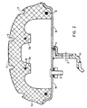
- FIG. 2 Another embodiment is shown in FIG. 2.
- the inside of the upper part (5) is interrupted by recesses, which are each guided up to about half the height of the upper part.
- the inside is given the contour shown in FIG. 2 with the circumferential cams (5b), which are arranged under the profile grooves (6) and, like the flanks (5a), are reinforced by circumferential cores (8).
- the remaining digits in FIG. 2 have the same meaning as in FIG. 1.
- the tire additionally contains a circumferential support ring (10) seated on the rim (1a, b) with a plurality of circumferential holes (10a) for the passage of air.
- the side walls of the support ring lie firmly against the inner wall of the tire flanks (5a).
- the distance between the support ring and the cams (5b) is such that the deflection movements of the upper tire part (5) are not impaired in normal operation.
- the support ring can be made of any suitable material, e.g. made of plastic or metal.
- Fig. 4 shows such a tire with loss of pressure.
- the support cams sit on the support ring (10) so that the tread forms a practically flat surface, while the tire does not change significantly in the flanks.
- the wire core (8) is inserted into the lamella holder (14) in the lower mold part (13). Then the inner parts (26, 28, 27, 21) are inserted into the mold via the transport hook (22). The other wire cores (8) are already applied to the lamella brackets (25) before assembly. After that, go to the top The last wire core (8) is placed on the slat. Following this, the components (17, 19, 16 and 15), actuated by pistons, move downwards. The component (15) is pressed inwards over the cone (20) until the press is closed. The tire is then filled via the injection channel (11). The presses are opened in reverse order, with the plate spring (18) increasing the lifting effect.
- the tires and the inner molded parts are again removed via the transport hook (22).
- the tire is then exposed at a central demolding point, while a second core which has already been assembled is introduced into the mold and the next tire is produced in the sequence described above.
- the tire is heated for 5 to 8 minutes at temperatures of 145-175 ° C.
- the tire does not have to be constructed from several layers of different material as in conventional tires, but can, apart from the circumferential wire or textile reinforcements, be made from a uniform rubber or rubber mixture.
- All natural or synthetic rubbers are suitable, the vulcanizates of which have a Shore hardness of 55 to 90 and a tension value of 100-200 kp / cm 2 at 300% elongation.
- Particularly suitable are: natural rubber, styrene-butadiene rubber, polybutadiene rubber and ethylene Propylene terpolymer rubber.
- tire flanks which may be added by adding e.g. modified novolaks or glass fibers are reinforced and have a greater Shore hardness.
Landscapes
- Engineering & Computer Science (AREA)
- Mechanical Engineering (AREA)
- Tires In General (AREA)
Applications Claiming Priority (2)
| Application Number | Priority Date | Filing Date | Title |
|---|---|---|---|
| DE3138582 | 1981-09-29 | ||
| DE19813138582 DE3138582A1 (de) | 1981-09-29 | 1981-09-29 | Reifen fuer kraftfahrzeuge |
Publications (1)
| Publication Number | Publication Date |
|---|---|
| EP0083391A2 true EP0083391A2 (fr) | 1983-07-13 |
Family
ID=6142835
Family Applications (1)
| Application Number | Title | Priority Date | Filing Date |
|---|---|---|---|
| EP82108530A Withdrawn EP0083391A2 (fr) | 1981-09-29 | 1982-09-16 | Bandage pneumatique pour véhicules |
Country Status (5)
| Country | Link |
|---|---|
| US (1) | US4467852A (fr) |
| EP (1) | EP0083391A2 (fr) |
| JP (1) | JPS5873403A (fr) |
| CA (1) | CA1190129A (fr) |
| DE (1) | DE3138582A1 (fr) |
Cited By (2)
| Publication number | Priority date | Publication date | Assignee | Title |
|---|---|---|---|---|
| EP0192112A3 (fr) * | 1985-02-16 | 1987-12-16 | Bayer Ag | Bandage pneumatique pouvant rouler à l'état dégonflé |
| EP0139507B1 (fr) * | 1983-10-11 | 1989-05-24 | Unisys Corporation | Feuilles d'enregistrement insulaires et leur fabrication |
Families Citing this family (13)
| Publication number | Priority date | Publication date | Assignee | Title |
|---|---|---|---|---|
| DE3345367A1 (de) * | 1983-12-15 | 1985-06-27 | Continental Gummi-Werke Ag, 3000 Hannover | Fahrzeugrad |
| GB8517959D0 (en) * | 1985-07-16 | 1985-08-21 | Sp Tyres Uk Ltd | Motor cycle tyres |
| US4823854A (en) * | 1986-01-27 | 1989-04-25 | Motor Wheel Corporation | Safety tire and rim combination with safety insert |
| US5000241A (en) * | 1989-05-09 | 1991-03-19 | Patecell Theodore C | Unitary bead-lock and run-flat roller support ring for pneumatic tires on two-part wheels |
| US5022450A (en) * | 1989-11-06 | 1991-06-11 | Motor Wheel Corporation | Safety tire and take-apart wheel construction |
| US5499669A (en) * | 1994-07-14 | 1996-03-19 | Deere & Company | Reinforced semi-pneumatic tire |
| US5533793A (en) * | 1995-03-17 | 1996-07-09 | Gleason Corporation | Agricultural tires and wheel assemblies therefore |
| DE19745409C2 (de) * | 1997-10-15 | 2002-06-20 | Continental Ag | Fahrzeugrad mit einem Notlaufstützkörper |
| AU7785200A (en) * | 1999-09-29 | 2001-04-30 | Michelin Recherche Et Technique S.A. | Safety support with noise suppressor for vehicle wheel |
| US6499521B2 (en) | 2000-06-07 | 2002-12-31 | The Goodyear Tire & Rubber Company | Low aspect ratio pneumatic tire without sidewalls |
| US7086438B1 (en) | 2000-08-30 | 2006-08-08 | Vossberg Stephen M | Pneumatic tire having a stabilizing system for under-inflated conditions |
| US7726536B2 (en) * | 2004-04-02 | 2010-06-01 | Black & Decker Inc. | Upper bumper configuration for a power tool |
| CA2902079A1 (fr) * | 2015-08-31 | 2017-02-28 | Tomo Bonac | Pneu coussin |
Family Cites Families (3)
| Publication number | Priority date | Publication date | Assignee | Title |
|---|---|---|---|---|
| US485633A (en) * | 1892-11-08 | Cushion-tire and rim therefor | ||
| FR680856A (fr) * | 1928-09-08 | 1930-05-07 | Bandage en caoutchouc pour roues de véhicules | |
| US2600033A (en) * | 1948-04-13 | 1952-06-10 | Hamlin Metal Products Company | Toy wheel and method of making |
-
1981
- 1981-09-29 DE DE19813138582 patent/DE3138582A1/de not_active Withdrawn
-
1982
- 1982-09-16 EP EP82108530A patent/EP0083391A2/fr not_active Withdrawn
- 1982-09-16 US US06/418,748 patent/US4467852A/en not_active Expired - Fee Related
- 1982-09-24 JP JP57165134A patent/JPS5873403A/ja active Pending
- 1982-09-27 CA CA000412278A patent/CA1190129A/fr not_active Expired
Cited By (2)
| Publication number | Priority date | Publication date | Assignee | Title |
|---|---|---|---|---|
| EP0139507B1 (fr) * | 1983-10-11 | 1989-05-24 | Unisys Corporation | Feuilles d'enregistrement insulaires et leur fabrication |
| EP0192112A3 (fr) * | 1985-02-16 | 1987-12-16 | Bayer Ag | Bandage pneumatique pouvant rouler à l'état dégonflé |
Also Published As
| Publication number | Publication date |
|---|---|
| JPS5873403A (ja) | 1983-05-02 |
| US4467852A (en) | 1984-08-28 |
| CA1190129A (fr) | 1985-07-09 |
| DE3138582A1 (de) | 1983-04-07 |
Similar Documents
| Publication | Publication Date | Title |
|---|---|---|
| EP0083391A2 (fr) | Bandage pneumatique pour véhicules | |
| DE3218315C2 (fr) | ||
| DE69805741T2 (de) | Schwerlast-Radialluftreifen | |
| DE69906103T2 (de) | Scheitelbewehrung für Radialreifen | |
| DE1729756A1 (de) | Verfahren und Vorrichtung zum Herstellen von Luftreifen | |
| DE2237062A1 (de) | Luftreifen fuer fahrzeugraeder | |
| DE2522924A1 (de) | Sicherheitsreifen fuer kraftfahrzeuge und verfahren zu dessen herstellung | |
| DE2449668A1 (de) | Luftreifen | |
| EP0011698A1 (fr) | Anneau de sécurité pour bandages pneumatiques | |
| DE1505016A1 (de) | Verfahren zur Herstellung eines Luftreifens | |
| DE2944345A1 (de) | Gummifederreifen und verfahren zu seiner herstellung | |
| DE3101408A1 (de) | Fahrzeugreifen | |
| DE69107293T2 (de) | Luftreifen. | |
| DE2715105A1 (de) | Aufbau aus pneumatischem reifen und radfelge | |
| DE69812974T2 (de) | Aufbau von Wulstkernen und Wulstfüller | |
| DE2529597A1 (de) | Sicherheitsreifen | |
| DE69004350T3 (de) | Verfahren und Form zum Formen eines Reifens. | |
| DE69617018T2 (de) | Vollreifen und verfahren zur herstellung | |
| EP0173670A2 (fr) | Bandage pneumatique pour véhicule | |
| DE69000684T2 (de) | Radialluftreifen mit verbesserter laufleistung. | |
| DE69933021T2 (de) | Schwerlastgürtelreifen | |
| EP0192112A2 (fr) | Bandage pneumatique pouvant rouler à l'état dégonflé | |
| DE2900717A1 (de) | Verfahren und vorrichtung zum formen und vulkanisieren von reifen ohne entlueftungsvorspruenge | |
| DE102016211332A1 (de) | Verfahren zur Herstellung eines Vollgummireifens und nach dem Verfahren hergestellter Vollgummireifen | |
| DE69309671T2 (de) | Verfahren zur Herstellung von Radialluftreifen |
Legal Events
| Date | Code | Title | Description |
|---|---|---|---|
| PUAI | Public reference made under article 153(3) epc to a published international application that has entered the european phase |
Free format text: ORIGINAL CODE: 0009012 |
|
| 17P | Request for examination filed |
Effective date: 19820916 |
|
| AK | Designated contracting states |
Designated state(s): AT BE DE FR GB IT LU NL SE |
|
| STAA | Information on the status of an ep patent application or granted ep patent |
Free format text: STATUS: THE APPLICATION HAS BEEN WITHDRAWN |
|
| 18W | Application withdrawn |
Withdrawal date: 19840109 |
|
| R18W | Application withdrawn (corrected) |
Effective date: 19840109 |
|
| RIN1 | Information on inventor provided before grant (corrected) |
Inventor name: STUETTGEN, FRIEDEL Inventor name: IPPEN, JAKOB, DR. |