EP0083423B1 - Plasmabildschirmsystem mit Abfragen durch selektive Unterhaltungsspannung - Google Patents
Plasmabildschirmsystem mit Abfragen durch selektive Unterhaltungsspannung Download PDFInfo
- Publication number
- EP0083423B1 EP0083423B1 EP82111310A EP82111310A EP0083423B1 EP 0083423 B1 EP0083423 B1 EP 0083423B1 EP 82111310 A EP82111310 A EP 82111310A EP 82111310 A EP82111310 A EP 82111310A EP 0083423 B1 EP0083423 B1 EP 0083423B1
- Authority
- EP
- European Patent Office
- Prior art keywords
- sustain
- gas panel
- cells
- panel system
- voltage
- Prior art date
- Legal status (The legal status is an assumption and is not a legal conclusion. Google has not performed a legal analysis and makes no representation as to the accuracy of the status listed.)
- Expired
Links
Images



Classifications
-
- G—PHYSICS
- G06—COMPUTING OR CALCULATING; COUNTING
- G06F—ELECTRIC DIGITAL DATA PROCESSING
- G06F3/00—Input arrangements for transferring data to be processed into a form capable of being handled by the computer; Output arrangements for transferring data from processing unit to output unit, e.g. interface arrangements
- G06F3/01—Input arrangements or combined input and output arrangements for interaction between user and computer
- G06F3/03—Arrangements for converting the position or the displacement of a member into a coded form
- G06F3/033—Pointing devices displaced or positioned by the user, e.g. mice, trackballs, pens or joysticks; Accessories therefor
- G06F3/038—Control and interface arrangements therefor, e.g. drivers or device-embedded control circuitry
- G06F3/0386—Control and interface arrangements therefor, e.g. drivers or device-embedded control circuitry for light pen
-
- G—PHYSICS
- G06—COMPUTING OR CALCULATING; COUNTING
- G06F—ELECTRIC DIGITAL DATA PROCESSING
- G06F3/00—Input arrangements for transferring data to be processed into a form capable of being handled by the computer; Output arrangements for transferring data from processing unit to output unit, e.g. interface arrangements
- G06F3/01—Input arrangements or combined input and output arrangements for interaction between user and computer
- G06F3/03—Arrangements for converting the position or the displacement of a member into a coded form
- G06F3/033—Pointing devices displaced or positioned by the user, e.g. mice, trackballs, pens or joysticks; Accessories therefor
Definitions
- This invention relates to optical detection of the contents of a selected pel or group of pels in a gas panel system comprising a gas panel and associated control and readout circuitry.
- the readout can be serial, or by sequential groups of pels, for such purposes as copying, communication, interaction or indication.
- cathode ray tube (CRT) displays wherein each pel is intensified at a unique time in a raster scan
- gas panels frequently use a sustain system that energizes, i.e. "fires", all of the pels making up a display image simultaneously.
- the pels of such gas panels are not differentiable with respect to time.
- one object of this invention is to use the write/erase addressing means to provide a selective sustain signal only used when a readout operation has to occur, using the memory effect of the gas panel system.
- a gas panel display system having an optical readout arrangement comprising a gas panel having X and Y lines, means for applying sustain voltage to the cells, means for selectively addressing a selected cell or cells, and optical detector means for detecting cell ignition in one or more cells, is characterised by means for reducing the voltage level output of the sustain signal application means during the first part of a selective sustain cycle so as to constitute a partial sustain signal having no independent effect, means for generating an extra voltage level corresponding to the amount by which the voltage level output of the sustain signal application means is reduced, and means for combining said partial sustain signal and said extra voltage level selectively in response to said addressing means, so that only the selected addressed cell or cells is or are subjected to the full sustain voltage.
- a gas panel system with X and Y coordinate lines has a selectable "selective sustain" cycle with the first half of the sustain drive partially or wholly missing at the positions of all or a large group of pels so as to constitute, at most, a partial-sustain signal having no independent effect.
- the missing half cycle component is supplied to a particular pel or pels by the addressing circuitry similarly to the write and erase pulses so that the information content at the addressed positions can be read optically.
- Fig. 1 shows an A.C. gas display panel 8 of the general kind described in U.S. Patent 3,976,992.
- X drive circuitry 10 and Y drive circuitry 12 operate respective arrays of conductors in front and. back plate structures of the panel to set up wall charges at X, Y intersections and to sustain those charges in an A.C. manner whereby dots or pels of light care seen at the X, Y points (herein referred to as cells) having such charge storage.
- Control and Timing circuitry 14 provides outputs 16 and 18 which are operable to control sustain drive circuitry 20 to operate the X, Y drivers 10, 12 to supply complementary A.C. voltages to the X, Y array in the usual manner.
- the system of Fig. 1 also includes a usual address inputs 22X, 22Y, and write and erase controls 24, 26.
- a selective sustain control 28 is provided, operable via control line 30 and gate 32 to modify the operation of the sustain drive 20 momentarily to render a sustain cycle effectively inoperative.
- control 14 operates via lines 34, 36 to superimpose supplementary sustain signals which-complement the modified sustain drive signals, at addresses specified via the inputs 22X and 22Y.
- the write and erase signals are those normally used in a gas panel.
- the gate 32 blocks the sustain drive for the X array panel conductors during the first half of the normal sustain cycle signal whereby the potential on those conductors is insufficient for sustain action.
- address data from inputs 22X, 22Y and enable drives on lines 34 and 36 are employed to complement (i.e. boost) a half sustain signal, during the first half of the sustain cycle, applied to the X line(s) of the selected cell(s) and to provide a half sustain signal applied to the Y lines of non-selected cell(s).
- the information stored in the panel will be identical to the initial condition. Some regular sustain cycles should be interspersed between the selective sustain cycles to prevent slow attrition of the stored condition.
- Fig. 2 illustrates this operation.
- an A.C. voltage 38 is applied between the X and Y arrays of conductors in the panel 8, thereby reversing the wall charge at each charged cell of the panel twice each sustain cycle.
- a single such cell 39 is shown undergoing this charge reversal.
- the gas at the cell is ionized and a flash of light 40 is emitted from the cell. Only the cell wall surfaces are shown. Wall constructions for A.C. gas panels are well known; U.S. Patents 4,053,804 and 4,207,488 show examples.
- a half cycle 41 of the sustain voltage 38 is altered so as to become insufficient in itself to ionize the cells. Therefore the cell wall charge remains unreversed and no light is emitted, as indicated at 42.
- the addressing mechanism is utilized to add a supplemental pulse 43 to the altered (half-sustain) pulse 41 so that, together, 41 and 43 are of sufficient amplitude to ionize the gas in the addressed cell so that its charge reverses and a light pulse is emitted, as shown at 44.
- the second half 45 of the altered sustain cycle occurs, the cell charge reverses and a flash of light is emitted again, as indicated at 46.
- the two charge reverse/flash emission occurrences 44 and 46 characterize the operation of the selected cell.
- Optical sensing means samples the light output at time 47 so as to detect the light pulses 48 emitted from the addressed cell only as opposed to light 40 from normal sustain operation before or after the selective sustain cycle.
- the second of the output pulses 48 is redundant. This redundancy can be used to check -proper operation of the panel or as an aid in discriminating against ambient optical noise, if desired.
- the detected light output indicates that the addressed cell was (and is) charged, i.e. it represents a "1" data bit or lighted pel. If no output is detected, then a "0" bit (unlighted pel) status of the cell can be inferred.
- the panel 8 may be considered for detection as divided up into a number of overlapping segments 50, 52, 54, and 56 (approximately quadrants). Four are shown. If needed, crossed polarizers 58, 60 are placed over the front (viewing) and rear sides of the panel, respectively. Each segment is viewed from the back by an optic fibre 62, so that in aggregate the fibres view the entire panel. More or fewer segments and fibres could be used, depending on the viewing angle of each fibre and the depth of the panel housing (not shown). The other ends of the optic fibres are bundled to direct their light through optic filter 64 to photo detector 66. The optic filter 64 is designed to pass primarily a prominent emission line of the gas in the gas panel.
- the cross polarizers 58 and 60 i.e. each comprises two light polarising sheets with their polarising planes at right angles) reduce ambient light incident on the front or back of the panel reaching the optic fibres.
- Photo detector 66 provides an electrical output proportional to the light from the entire panel. This light is a combination of any remaining ambient light which passed through 58, 60 and 64 and panel light which includes any selected pels plus any later recombination light from previous operation. The latter can be reduced by inhibiting all sustain operation for a short time before each selective sustain cycle is commenced.
- a band pass electrical filter 68 operates to distinguish the desired light pulse from ignited pels from the background light, by blocking all but the high slope pulses characteristic of the detected pel light.
- the signal from the band pass filter on line 70 indicates at least one ignited pel when it exceeds a threshold and conditions a gate in block 72 at the time of a sample pulse on line 74.
- This signal appears as an output on line 76 for storage in a buffer 78 or can be taken as a direct output 80 depending on the use to which the interrogation is being put.
- the sample pulse 47 may be long enough to sense both pulses 48, and circuitry (not shown) can be provided to make use of that redundancy.
- the selective sustain action can be applied to all pels in a row (or a column) simultaneously, or to a column-row set defining a portion of the panel.
- an output pulse merely indicates that at least one of the pels contains a logical "1". If successive halving of the group is done on successive cycles, the content of all pels can be resolved. This is especially valuable for maintaining reading speed in a panel containing sparse "1s" (the usual condition).
- an alternate sensing mechanism can be placed in a stylus 82 to provide light pen operation.
- the stylus 82 includes a colour filter similar to optic filter 64 and photo detector such as a photo transistor, and is connected via a flexible cable 84 to a band pass filter and amplifier 68'.
- the photo detector can be incorporated in element 68' and cable 84 can be a fibre optic link, for example.
- a switch 86 selects between the outputs of 68' and 68.
- Either sensing mechanism configuration (62 etc or 82 etc) can be used in conjunction with the buffer 78 to preserve the underlying information stored in the panel 8 for interactive signals generally and particularly to facilitate temporary replacement of data in the panel with, e.g. cursor symbol so that the cursor has freedom to occupy any position.
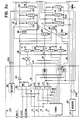
- Figs. 3a and 3b show an example of circuitry suitable for use in implementing the system of Fig. 1.
- Major elements of Fig. 1 are given corresponding reference numbers in Figs. 3a and 3b.
- the X, Y array of conductors in panel 8 are addressed by operation of circuits 10, 12 which are responsive to X and Y address decoders 100, 102 and are enabled for selective sustain operation by drivers 104, 106, via transformers 108, 110.
- This addressing and its enablement is also used for write and erase operations. Write and erase operations of this kind are well known in the prior art and do not form part of the present invention.
- Sustain drive 20 is shown to be implemented by pairs of drivers 112, 114 and 116,118 which in normal sustain operation provide +E and ground levels in alternation, so as to impose the regular sustain waveform 38 of Fig. 2 on busses 120X, 120Y of the X, Y drive circuitries 10, 12.
- bus 120X is at +E and bus 120Y is at ground.
- bus 120X is at ground and bus 120Y is at +E.
- both busses are at +E/2. Voltage levels +E, +E/2 and ground are supplied as shown in Fig. 3a.
- Selective sustain operation is provided by the introduction of gate 32 in the base control of bus driver 112.
- Gate 32 is an AND circuit having one input 16 which in other respects is like the base drive inputs 18 to the other bus drivers.
- the other input 30 to gate 32 is applied through an inverting input thereto.
- an "up" Selective System control signal on lines 28, 30 is operative to inhibit operation of driver 112 so that, when the companion driver 114 is turned off by timing 125, bus 120X rises only to voltage E/2, which is the half sustain level 41 shown in Fig. 2.
- Decoders 110, 102 energize lines 22XD and 22YD in accordance with the addresses supplied from any desired source (not shown), such as a computer, counter, etc.
- the addresses can define a unique pel, or they can be "broadcast" addresses which are decodable at 100, 102 to energize groups of lines 22XD and 22YD to define quadrants or other segments of the panel 8.
- the signals. on lines 22XD are down-level significant and on lines 22YD are up-level significant i.e. respectively down and up for each selected cell.
- the signals on lines 22XD and 22YD are applied as base drives to transistors 120, 122,...124 and 126, 128,...130 and when up clamp respective X panel drive lines 132, 134...136 and Y panel drive lines 138, 140...142 to the respective busses 120X, 120Y by an amount supplied, via the respective collector resistors for those transistors, from the respective secondary windings of transformers 108 and 110.
- those X panel lines which are addressed by a down level on the respective lines 22XD receive the output signal on bus 120X of sustain drive circuit 20 plus an A.C. component from transformer 108.
- This A.C. component from the X transformer 108 supplies the supplemental pulse signal 43 (Fig. 2) when driver 104 is turned on.
- Y panel lines are addressed, in this case by an up level, on respective lines 22YD which clamps the addressed lines to the bus 120Y.
- transformers 108 and 110 not only enable the associated transistors 126, 128...130 and 120, 122...124 with collector voltage; they also provide pulses used as components of the selective sustain signals.
- Tables I and II summarize the operation for normal and selective sustain cycles, respectively:
- non-addressed cells including half-selected cells
- Y line 140 is not selected. This is a half select condition. It will be observed that the voltage difference at such a half select cell is +E/2. This is not sufficient to ignite the cell.
- Figs. 3a and 3b also show schematic representations of input logic for operation of the above described circuitries, and output devices for detecting and utilizing the information read from the panel 8 as aforesaid.
- the addresses received on lines 22X and 22Y can be from any convenient source such as a data processing system (not shown). The same source can supply the Write, Erase and Selective Sustain commands on lines 24, 26 and 28, respectively. Each of these command signals cooperate with timing 125 and AND, OR circuitry as shown to provide the required signals on lines 30, 34 and 36. Timing 125 can be free running, or responsive to the commands, as desired. In either event, the desired timing outputs are selected by AND gates 150, 152, 154, 156 as shown. Appropriate voltage levels are provided as shown to energize analog gates 158,160,162 to provide drive voltage via amplifier 164, as selected by the commands on lines 24, 26, 28.
- AND gate 154 is energized for the first half of the selective sustain cycle, and its output could be used to operate the sense gate 72 by which a detected light pulse can be passed to the output. However, gate 154 is operative only during the first half of a selective sustain cycle. To sense both flashes 44 and 46, a full selective sustain cycle time signal 170 is ANDed at 156 to provide a sense timing signal on line 74 which strobes the sense gate 72. Gate 154 can be used to step the output buffer 78 once each selective sustain cycle, via line 176. The redundant pulse from gate 72 will simply over-write in buffer 78. A serial output 80 will provide a pulse for each detected flash, however, and can be used as an input to error detecting circuitry, not shown, if desired.
- the output at 80 can also be used, by connection to a data processor which provides the input addresses and commands, as a source of information on a real-time basis for executing routines for carrying out a rapid search of the panel 8. This could provide a fast means of skipping over blank lines or shorter segments by multiple pel read out with elimination of areas of all zero readout and successive halving of the size of areas with at least a single "1" bit readout.
- the buffer 78 can serve as a "scratch pad" memory to preserve data which is temporarily traversed on the display as the processor moves a cursor through the data field.
- the mechanics of using a scratch pad buffer are well known; therefore the read out means for buffer 78 are not shown.
- the panel cells need be picture elements, i.e. "pels” in the usual sense. However, the cells, whether or not visible to an observer, should be “visible” to the detection apparatus, such as from the back of the panel, as described.
Landscapes
- Engineering & Computer Science (AREA)
- General Engineering & Computer Science (AREA)
- Theoretical Computer Science (AREA)
- Human Computer Interaction (AREA)
- Physics & Mathematics (AREA)
- General Physics & Mathematics (AREA)
- Control Of Indicators Other Than Cathode Ray Tubes (AREA)
Claims (10)
Applications Claiming Priority (2)
| Application Number | Priority Date | Filing Date | Title |
|---|---|---|---|
| US336526 | 1981-12-31 | ||
| US06/336,526 US4525707A (en) | 1981-12-31 | 1981-12-31 | Gas panel interrogation by selective sustain |
Publications (3)
| Publication Number | Publication Date |
|---|---|
| EP0083423A2 EP0083423A2 (de) | 1983-07-13 |
| EP0083423A3 EP0083423A3 (en) | 1984-06-13 |
| EP0083423B1 true EP0083423B1 (de) | 1987-04-01 |
Family
ID=23316501
Family Applications (1)
| Application Number | Title | Priority Date | Filing Date |
|---|---|---|---|
| EP82111310A Expired EP0083423B1 (de) | 1981-12-31 | 1982-12-07 | Plasmabildschirmsystem mit Abfragen durch selektive Unterhaltungsspannung |
Country Status (4)
| Country | Link |
|---|---|
| US (1) | US4525707A (de) |
| EP (1) | EP0083423B1 (de) |
| JP (1) | JPS58120293A (de) |
| DE (1) | DE3275952D1 (de) |
Family Cites Families (7)
| Publication number | Priority date | Publication date | Assignee | Title |
|---|---|---|---|---|
| US3796997A (en) * | 1972-11-24 | 1974-03-12 | Univ Illinois | Optical read-out/read-in apparatus for plasma display/memory panels |
| US3919591A (en) * | 1973-06-29 | 1975-11-11 | Ibm | Gas panel with improved write-erase and sustain circuits and operations |
| US3887767A (en) * | 1973-10-01 | 1975-06-03 | Owens Illinois Inc | Method of and system for light pen read-out multicelled gaseous discharge display/memory device |
| US3976992A (en) * | 1975-01-03 | 1976-08-24 | Ibm Corporation | Gas display panel with light pen |
| JPS5254336A (en) * | 1975-10-30 | 1977-05-02 | Fujitsu Ltd | Coordinate reading for gas discharge panel |
| JPS5260034A (en) * | 1975-11-12 | 1977-05-18 | Fujitsu Ltd | Reading system of gas discharge panel |
| US4117471A (en) * | 1976-08-18 | 1978-09-26 | International Business Machines Corporation | Light pen detection and tracking with ac plasma display panel |
-
1981
- 1981-12-31 US US06/336,526 patent/US4525707A/en not_active Expired - Lifetime
-
1982
- 1982-12-07 EP EP82111310A patent/EP0083423B1/de not_active Expired
- 1982-12-07 DE DE8282111310T patent/DE3275952D1/de not_active Expired
- 1982-12-09 JP JP57214798A patent/JPS58120293A/ja active Granted
Also Published As
| Publication number | Publication date |
|---|---|
| JPS58120293A (ja) | 1983-07-18 |
| EP0083423A2 (de) | 1983-07-13 |
| DE3275952D1 (en) | 1987-05-07 |
| EP0083423A3 (en) | 1984-06-13 |
| JPH0339318B2 (de) | 1991-06-13 |
| US4525707A (en) | 1985-06-25 |
Similar Documents
| Publication | Publication Date | Title |
|---|---|---|
| US4742344A (en) | Digital display system with refresh memory for storing character and field attribute data | |
| EP0179193B1 (de) | Datenanzeigesystem mit Möglichkeit zum Mischen von Anzeigequellen und mit Benutzung eines Anzeigegerätes vom Speichertyp | |
| KR930002927A (ko) | 변형가능한 디스플레이 메모리 제공방법 및 장치 | |
| US4291305A (en) | Method for generating format lines and character data in an image scanning system | |
| US3958234A (en) | Interactive stylus sensor apparatus for gas panel display | |
| US4208723A (en) | Data point connection circuitry for use in display devices | |
| EP0083423A2 (de) | Plasmabildschirmsystem mit Abfragen durch selektive Unterhaltungsspannung | |
| GB1565076A (en) | Plasma display panels | |
| US3796997A (en) | Optical read-out/read-in apparatus for plasma display/memory panels | |
| US3887767A (en) | Method of and system for light pen read-out multicelled gaseous discharge display/memory device | |
| US3949391A (en) | Plasma panel light pen tracking using adaptive tracking scan | |
| SU970438A1 (ru) | Устройство дл отображени информации | |
| SU951379A1 (ru) | Устройство дл отображени информации | |
| SU1478207A1 (ru) | Устройство дл отображени системы координат на экране электронно-лучевой трубки | |
| SU1352521A1 (ru) | Устройство дл отображени информации | |
| SU1042070A1 (ru) | Устройство дл отображени информации на газоразр дной индикаторной панели | |
| KR100522799B1 (ko) | 플라즈마 디스플레이 패널의 진단 장치 | |
| SU1437852A1 (ru) | Устройство дл отображени информации | |
| SU1411810A1 (ru) | Устройство дл отображени информации | |
| SU938308A1 (ru) | Устройство дл отображени информации на экране электронно-лучевой трубки | |
| JPS5817959B2 (ja) | プラズマ デイスプレイ ノ ザヒヨウヨミダシホウシキ | |
| SU1451761A1 (ru) | Устройство дл отображени информации на экране матричного индикатора | |
| SU1401447A1 (ru) | Устройство дл отображени информации на экране телевизионного индикатора | |
| SU1434423A1 (ru) | Устройство дл отображени информации | |
| SU991477A1 (ru) | Устройство дл обучени |
Legal Events
| Date | Code | Title | Description |
|---|---|---|---|
| PUAI | Public reference made under article 153(3) epc to a published international application that has entered the european phase |
Free format text: ORIGINAL CODE: 0009012 |
|
| AK | Designated contracting states |
Designated state(s): DE FR GB |
|
| 17P | Request for examination filed |
Effective date: 19831021 |
|
| PUAL | Search report despatched |
Free format text: ORIGINAL CODE: 0009013 |
|
| AK | Designated contracting states |
Designated state(s): DE FR GB |
|
| GRAA | (expected) grant |
Free format text: ORIGINAL CODE: 0009210 |
|
| AK | Designated contracting states |
Kind code of ref document: B1 Designated state(s): DE FR GB |
|
| REF | Corresponds to: |
Ref document number: 3275952 Country of ref document: DE Date of ref document: 19870507 |
|
| ET | Fr: translation filed | ||
| PLBE | No opposition filed within time limit |
Free format text: ORIGINAL CODE: 0009261 |
|
| STAA | Information on the status of an ep patent application or granted ep patent |
Free format text: STATUS: NO OPPOSITION FILED WITHIN TIME LIMIT |
|
| 26N | No opposition filed | ||
| PGFP | Annual fee paid to national office [announced via postgrant information from national office to epo] |
Ref country code: GB Payment date: 19921126 Year of fee payment: 11 |
|
| PG25 | Lapsed in a contracting state [announced via postgrant information from national office to epo] |
Ref country code: GB Effective date: 19931207 |
|
| GBPC | Gb: european patent ceased through non-payment of renewal fee |
Effective date: 19931207 |
|
| PGFP | Annual fee paid to national office [announced via postgrant information from national office to epo] |
Ref country code: FR Payment date: 19971210 Year of fee payment: 16 |
|
| PGFP | Annual fee paid to national office [announced via postgrant information from national office to epo] |
Ref country code: DE Payment date: 19971216 Year of fee payment: 16 |
|
| PG25 | Lapsed in a contracting state [announced via postgrant information from national office to epo] |
Ref country code: FR Free format text: LAPSE BECAUSE OF NON-PAYMENT OF DUE FEES Effective date: 19990831 |
|
| REG | Reference to a national code |
Ref country code: FR Ref legal event code: ST |
|
| PG25 | Lapsed in a contracting state [announced via postgrant information from national office to epo] |
Ref country code: DE Free format text: LAPSE BECAUSE OF NON-PAYMENT OF DUE FEES Effective date: 19991001 |