EP0083507A2 - Hydraulische Schlagantriebe mit Ausräumung des Bohrmeissels - Google Patents
Hydraulische Schlagantriebe mit Ausräumung des Bohrmeissels Download PDFInfo
- Publication number
- EP0083507A2 EP0083507A2 EP82307000A EP82307000A EP0083507A2 EP 0083507 A2 EP0083507 A2 EP 0083507A2 EP 82307000 A EP82307000 A EP 82307000A EP 82307000 A EP82307000 A EP 82307000A EP 0083507 A2 EP0083507 A2 EP 0083507A2
- Authority
- EP
- European Patent Office
- Prior art keywords
- piston
- drill bit
- feed tube
- hammer
- bore
- Prior art date
- Legal status (The legal status is an assumption and is not a legal conclusion. Google has not performed a legal analysis and makes no representation as to the accuracy of the status listed.)
- Withdrawn
Links
- 239000012530 fluid Substances 0.000 title claims abstract description 79
- 238000005520 cutting process Methods 0.000 description 11
- 230000000694 effects Effects 0.000 description 4
- 230000000717 retained effect Effects 0.000 description 4
- 238000005553 drilling Methods 0.000 description 3
- 238000012423 maintenance Methods 0.000 description 3
- 238000007789 sealing Methods 0.000 description 3
- 230000005540 biological transmission Effects 0.000 description 1
- 239000000463 material Substances 0.000 description 1
- 239000011435 rock Substances 0.000 description 1
- 125000006850 spacer group Chemical group 0.000 description 1
Images


Classifications
-
- E—FIXED CONSTRUCTIONS
- E21—EARTH OR ROCK DRILLING; MINING
- E21B—EARTH OR ROCK DRILLING; OBTAINING OIL, GAS, WATER, SOLUBLE OR MELTABLE MATERIALS OR A SLURRY OF MINERALS FROM WELLS
- E21B4/00—Drives for drilling, used in the borehole
- E21B4/06—Down-hole impacting means, e.g. hammers
- E21B4/14—Fluid operated hammers
Definitions
- THIS INVENTION relates to down hole fluid operated hammers and drill bits for use with rock drilling to form bore holes and relates to a means of clearing the drill bit of cuttings.
- the drill bit is normally longitudinally slidably engaged in a drill chuck via a splined arrangement.
- the slidable engagement enables the hammer to be deactivated when the drill bit is removed from its contact with the bottom of the bore hole while the splined interconnection permits a torque to be applied to the drill bit by the rotating drill stem.
- a fluid operated hammer comprising a. cylindrical' casing having a bore for slidably receiving a piston, a top sub mounted at one end, a drill bit mounted to the other end by means of a chuck, a feed tube concentrically mounted within the upper end of the bore of the casing and extending downwardly into the casing, said feed tube being connectable to a fluid source through said top sub, a piston slidably mounted within the bore of said casing over said feed tube, at least one aperture provided in the walls of said feed tube, at least one port provided at each end of the piston, each port opening at spaced locations into the bore of the piston to periodically communicate with said aperture as a result of slidable movement of the piston over the feed tube to alternatively drive the piston towards the drill bit to impact thereon and to drive the piston away from the drill bit; a further aperture provided in said feed tube to communicate with the space between said drill bit and said piston when said hammer is in the "blow-down" position and said drill bit
- the communication between said further aperture and said space is via the port provided at the drill bit end of the piston.
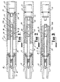
- the first embodiment of Figs. 1, 2 and 3 is a fluid operated hammer which comprises a cylindrical casing 11 having a substantially uncontoured inner face with a top sub 12 mounted at one end and a drill bit 13 mounted at the other end.
- the drill bit is mounted within a drill chuck which is threadably engaged in the other end of the casing such that it is longitudinally slidable for a limited degree within the end of the chuck.
- Such limited slidable movement of the drill bit is facilitated by a bit ring 14 mounted in the inner end of the chuck and which is received within a waisted portion 15 of the innermost end of the drill bit.
- the innermost end of the drill bit 13 which extends beyond the bit ring 14 is formed with an enlarged portion which serves as the anvil 16 for the drill bit 13.
- the mounting of the drill bit in the chuck is via a splined arrangement permitting the limited longitudinal sliding movement of the drill bit in the chuck but ensuring a transmission of torque from the drill stem to the drill bit.
- the splined interconnection is such that the interior of the hammer is sealed from the exterior of the drill bit, however on the drill bit dropping to its lower-most position in the chuck (i.e. its blow-down position) the interior of the hammer above the drill bit is in communication with the exterior of the drill bit through the splined interconnection.
- the top sub 12 is threadably engaged in the one end of the casing 11 and is provided with a fluid inlet port 17 which communicates with a spring loaded check valve 18 located within the top sub to prevent any reverse,fluid flow.
- the bore of the casing 11 supports a feed tube 20 which is concentrically mounted at the one end of the bore of the casing 11 in abutting relation with the inner end of the top sub 12.
- the feed tube 20 extends from the one end of the casing for a portion of the length of the casing.
- the mounting of the feed tube comprises a centralising ring which is accurately, closely and concentrically retained in the one end of the bore. The centralising ring receives the one end of the feed tube and accurately retains the feed tube such that it is concentrically located within the casing 11.
- a flange at the one end of the feed tube overlies the outer axial face of the centralising ring to be located within a suitably shaped recess formed within the top sub 12. Suitable tolerances are provided between the top sub 12 and the flanged end of the feed tube in order that any mis-alignment of the top sub will not effect the alignment of the feed tube 20 within the casing as established by the spacer ring. Suitable resilient sealing and accommodating means in the form of 0-rings are provided in the centralising space between the centralising ring and the flanged of the feed tube and the top sub 12 and the flanged of the feed tube to prevent any loss of fluid from the junctions therebetween and to allow some movement of the feed tube.
- the centralising ring provides a means of supporting and centralising the feed tube concentrically within the bore of the casing 11 and thus the piston 26.
- the free end of the feed tube is provided with a suitably dimensioned choke 23 which permits a controlled continuous flow of fluid down through the drill bit 13.
- the walls of the feed tube are uncontoured and are formed with three sets of apertures.
- One set 24 comprises a single aperture which extends for a considerable portion of the circumference of the feed tube but which has a relatively small dimension in the longitudinal axis of the feed tube.
- the one set may comprise a series of circumferentially spaced apertures in the walls of the feed tube which have a relatively small axial dimension.
- the other set of apertures comprise a pair of longitudinally spaced apertures 25a and 25b located towards the free end of the feed tube from the one set of apertures 24.
- One aperture 25a of the other set of apertures which is located closest to said one set of apertures 24 is greater in size than the other of said apertures 25b and has a greater axial dimension than the other aperture 25b.
- a third set of apertures 40 is located between the first and second sets 24 and 25.
- the hammer further supports within the casing 11 a piston 26 which is longitudinally slidable within said casing 11 and over said feed tube 20.
- Each end of said piston is provided with a port 27 and 29 which communicates via a passage-way 28 or 30 extending respectively from the top sub end and drill bit end to the internal bore of said piston.
- the passage-ways 28 and 30 are formed by obliquely boring a hole from the respective end of said piston to the bore of said piston.
- the end of the piston adjacent the top sub 12 is counterbored to provide an expanded portion 31 in the bore of the piston which extends for a small portion of the length of the bore.
- Fluid pressure is admitted into the space between the piston 26 and the drill bit 13 through the third set of ports 40 and the port 29 in the drill bit end of the piston. However this pressure is vented through the splined interconnection between the drill bit and chuck to prevent the collection of cuttings in the space between the drill bit and chuck during "blow-down". Fluid from the top sub end of the piston escapes to the drill bit via port 27 and the one passage-way 28.
- the one set of apertures Due to the small axial dimension of the one set of apertures if the piston should for some reason be moved from engagement with the anvil a considerable degree of movement of the piston is required for the one set of apertures to communicate with the drill bit end of the piston through the passage-way 30 and port 29.
- the small axial dimension of the one set of apertures ensures that there can be no overlap between the counter-bored portion and the passage-way 28 by the one set of apertures. Therefore, the possibility of back hammer is considerably reduced.
- the one set of apertures 24 can be positioned to communicate fully with the drill bit end of the piston when the piston is raised a small distance from the anvil in order to make use of the reactive rebound of the piston after striking the anvil 16 in returning the piston to its position adjacent the centralising ring 21.
- the pressure producing the thrust on the piston 26 is reduced once the opening of the one passage-way 28 into the bore of the piston 26 passes the one aperture 25a but is further reinforced when the opening of the one passage-way 28 communicates with the other aperture 25b of the other set of apertures 25 during the movement of the piston 26 toward the drill bit.
- the frequency and force of impact of the piston 26 on the drill bit can be varied according to the geological conditions in which the hammer is being used or the pressure of the fluid being used. To effect such variation requires the replacement of the feed tube 20 only.
- the performance characteristics can be optimised to suit the conditions or specifications of the holes being drilled.
- the second embodiment of Figs. 4, 5 and 6 is a fluid operated hammer which comprises a cylindrical casing 111 having a substantially uncontoured inner face with a top sub 112 mounted at one end and a drill bit 113 mounted at the other end in the same manner as the first embodiment and having the same features as the hammer of the first embodiment including the splined interconnection between the chuck 141 and bit which was described in the description of the first embodiment.
- the casing 111 further supports a feed tube 10 which is concentrically mounted at the one end of the casing 111 in abutting relation with the inner end of the sub 112.
- the feed tube 20 extends from the one end of the casing for a portion of the length of the casing.
- the mounting of the feed tube is of the same form as that shown and described in the first embodiment.
- the free end of the feed tube is provided with a suitably dimensioned choke 123 which permits a controlled continuous flow of fluid down through the drill bit 113.
- the walls of the feed tube are uncontoured and are formed with three sets of apertures.
- One set of 124 comprises a single aperture which extends for a considerable portion of the circumference of the feed tube but which has a relatively small dimension in the longitudinal axis of the feed tube.
- the one set may comprise a series of circumferentially spaced apertures in the walls of the feed tube which have a relatively small axial dimension.
- the other set of apertures comprise a pair of longitudinally spaced apertures 125a and 125b located towards the free end of the feed tube from the one set of apertures 124.
- One aperture 125a of the other set of apertures which is located closest to said one set of apertures 124 and is greater in size than the other of said apertures 125b and has a greater axial dimension than the other aperture 125b.
- a third set of apertures 140 is located between the first and second set 124 and 125.
- the happer further supports within the casing 111 a piston 126 which is longitudinally slidable within said casing 111 and over said feed tube 120.
- One end of said piston is provided with a port 127 while another port 129 is located at an intermediate position on the piston.
- Said ports communicate with a passage-way 128 and 130 respectively extending from the respective port to the internal bore of said piston.
- the passage-ways 128 and 130 are formed by obliquely boring a hole from the position of the respective port of said piston to the bore of said piston.
- the end of the piston adjacent the top sub 112 is counterbored to provide an expanded portion 131 in the bore of the piston which extends for a small portion of the length of the bore.
- the circumferential face of the piston 126 between the position of the other port 129 and the other end of the piston which is adjacent the drill bit is machined to reduced diameter and the outer end of that reduced diameter portion 132 is formed with a rib 133.
- the drill bit end of the casing supports a sleeve 134 which extends a small distance beyond the innermost position of the anvil 116 of the drill bit 113.
- the inner most end of the sleeve 134 is formed with a rib 135 dimensioned such that the rib 133 at the other end of the piston 126 sealingly engages with the rib 135 on the sleeve when they are adjacent each other.
- Fluid pressure is admitted into the space between the piston 126 and the drill 113 through the third set of ports 140 and the port 129 in the drill bit end of the piston. However this fluid pressure is vented through the splined interconnection 141 between the drill bit and chuck to prevent the collection of cuttings in the space between the drill bit and chuck during "blow-down". Fluid from the top sub end of the piston escapes to the drill bit via one port 127 and the one passage 128.
- the one set of apertures Due to the small axial dimension of the one set of apertures if the piston should for some reason be moved from engagement with the anvil a fair degree of movement of the piston is required for the one set of apertures to communicate with the drill bit end of the piston through the passage-way 130 and port 129.
- the small axial dimension of the one set of apertures ensures that there can be no overlap between the counter-bored portion and the passage-way 128 by the one set of apertures. Therefore, the possibility of back hammer is considerably reduced.
- the one set of apertures 124 can be positioned to communicate fully with the drill bit end of the piston when the piston is raised a small distance from the anvil in order to make use of the reactive rebound of the piston after striking the anvil 16 in returning the piston to its position adjacent the centralising ring 121.
- the pressure producing the thrust on the piston 126 is reduced once the opening of the one passage-way 128 into the bore of the piston 126 passes the one aperture 125a but is further reinforced when the opening of the one passage-way 128 communicates with the other aperture 125b of the other set of apertures 125 during the movement of the piston 126 toward the drill bit.
- the third embodiment of Figs. 7, 8 and 9 is a fluid operated hammer which comprises a cylindrical casing 211 having a substantially uncontoured inner face with a top sub 212 mounted at one end and a drill bit 213 mounted at the other end in the same manner and having the same features as the hammer of the first embodiment including the splined interconnection 241 between the chuck and bit which is described and shown in the description of the first embodiment.
- the casing 211 further supports a feed tube 220 which is concentrically mounted at the one end of the casing 211 in abutting relation with the inner end of the top sub 212.
- the feed tube 220 extends from the one end of the casing for substantially the full length of the casing 211 such that its free end is received in the bore of the drill bit 213 when the drill bit 213 is in its innermost position in the casing but it is free of the drill bit when the drill bit is in its outer most position within the casing 211.
- the mounting of the feed tube to the top sub 212 is of the same form as that shown and described in relation to the first embodiment.
- the centralising ring 221 may be readily exchanged with other rings of differing thickness in order that the volume of the space between the upper end of the piston 226 and the top sub may be varied.
- the walls of the feed tube are uncontoured and are formed with three sets of apertures.
- One set 224 comprises a single aperture which extends for a considerable portion of the circumference of the feed tube but which has a relatively small dimension in the longitudinal axis of the feed tube.
- the one set may comprise a series of circumferentially spaced apertures in the walls of the feed tube which have a relatively small axial dimension.
- the other set of apertures comprise a pair of longitudinally spaced apertures 225a and 225b located towards the free end of the feed tube from the one set of apertures 224.
- One aperture 225a of the other set of apertures which is located closest to said one set of apertures 224 is greater in size than the other of said apertures 225b and has a greater axial dimension than the other aperture 225b.
- a third set of apertures 240 is located between the first and second set 225 and 224.
- a choke 223 is located in the feed tube between the two sets of apertures 224 and 225 and the further set of apertures 236 to provide a controlled continous flow of fluid down through the dirll bit 213.
- the hammer further supports within the casing 211 a piston 226 which is longitudinally slidable within said casing 211 and over said feed tube 220.
- a piston 226 which is longitudinally slidable within said casing 211 and over said feed tube 220.
- One end of said piston is provided with a port 227 while another port 229 is located at an intermediate position on the piston said ports communicate with a passage-way 228 or 230 respectively extending from the respective port to the internal bore of said piston.
- the passage-ways 228 and 230 are formed by obliquely boring a passage-way from the position of the respective port on the exterior of said piston to the bore of said piston.
- the end of the piston adjacent the top sub 212 is counter-bored to provide an expanded portion 231 in the bore of the piston which extends for a small portion of the length of the bore.
- the circumferential face of the piston 226 between the intermediate position on the other port 229 and the other end of the piston 226 which is adjacent the drill bit is machined to provide a reduced diameter portion wherein the other end portion of that reduced diameter portion 232 is formed with a rib 233.
- the drill bit end of the casing supports a sleeve 234 which extends a small distance beyond the innermost position of the anvil 216 of the drill bit 213.
- the innermost end of the sleeve 234 is formed with a rib 235 dimensioned such that the rib 233 at the other end of the piston 226 sealingly engages with the rib 235 on the sleeve when adjacent each other.
- Fluid pressure is admitted into the space between the piston 126 and the drill bit 113 through the third set of apertures 240 and the post 229 in the drill bit end of the piston. However the pressure is vented through the splined interconnection 241 between the drill bit and chuck to prevent the collection of cuttings in the space between the drill bit and chuck during "blow-down". Fluid from the top sub end of the piston escapes to the drill bit via port 227 and the one passage-way 229 and the further aperture 236 located towards the free end of the feed tube.
- the further aperture 236 is dimensioned such that it permits as much flow as is possible into the drill bit to maximise the use of the fluid when in the "blow-down" position to clear cuttings from the bore hole.
- the one set of apertures Due to the small axial dimension of the one set of apertures if the piston should for some reason be moved from engagement with the anvil a fair degree of movement of the piston is required for the one set of apertures to communicate with the drill bit end of the piston through the passage-way 230 and port 229.
- the small axial dimension of the one set of apertures ensures that there can be no overlap between the counter-bored portion and the passage-way 228 by the one set of apertures. Therefore, the possibility of back hammer is considerably reduced.
- the one set of apertures 224 can be positioned to communicate fully with the drill bit end of the piston when the piston is raised a small distance from the anvil in order to make use of the reactive rebound of the piston after striking the anvil 16 in returning the piston to its position adjacent the centralising ring 221.
- the use of the sleeve 234 in the drill bit end of the casing 211 reduces the volume of the space into which the other port 229 delivers fluid to effect the movement of the piston towards the drill bit. This reduces the volume of fluid required to return the piston to its position adjacent the drill bit.
- the pressure producing the thrust on the piston 226 is reduced once the opening of the one passage-way 228 into the bore of the piston 226 passes the edge of the one aperture 225a but is. further reinforced when the opening of the one passage-way 228 communicates with the other aperture 225b of the other set of apertures 25 during the movement of the piston 26 toward the drill bit.
- the hammer of each embodiment may be used for bore holes disposed at any angle from a work station above and below the horizontal axis.
- the third set of apertures 40, 140 and 240 provide an additional outlet for fluid from the hammer into the bore hole when the hammer is in its "blow-down" mode. Therefore the flow of high pressure fluid into the bore hole is maximised when the hammer moves to the "blow-down” mode and the resultant sudden flow of fluid facilitates clearance of cutting from the bore hole.
- This effect of the third set of apertures is of particular relevance in small hammers where for maximum operational efficiency it is desirable to close off the lower end of the feed tube.
- the third set of apertures serve a similar function as a choke in the "blow-down" mode to augment the fluid flow through the centre of the chuck.
- the third set of apertures facilitate clearance of the splined interconnection between the drill bit and chuck but also further augment the fluid flow from the hammer when in the "blow-down" mode.
Landscapes
- Engineering & Computer Science (AREA)
- Life Sciences & Earth Sciences (AREA)
- Geology (AREA)
- Mining & Mineral Resources (AREA)
- Mechanical Engineering (AREA)
- Physics & Mathematics (AREA)
- Environmental & Geological Engineering (AREA)
- Fluid Mechanics (AREA)
- General Life Sciences & Earth Sciences (AREA)
- Geochemistry & Mineralogy (AREA)
- Earth Drilling (AREA)
Applications Claiming Priority (2)
| Application Number | Priority Date | Filing Date | Title |
|---|---|---|---|
| AUPF215082 | 1982-01-04 | ||
| AU2150/82 | 1982-01-04 |
Publications (2)
| Publication Number | Publication Date |
|---|---|
| EP0083507A2 true EP0083507A2 (de) | 1983-07-13 |
| EP0083507A3 EP0083507A3 (de) | 1983-09-07 |
Family
ID=3769318
Family Applications (1)
| Application Number | Title | Priority Date | Filing Date |
|---|---|---|---|
| EP82307000A Withdrawn EP0083507A3 (de) | 1982-01-04 | 1982-12-30 | Hydraulische Schlagantriebe mit Ausräumung des Bohrmeissels |
Country Status (3)
| Country | Link |
|---|---|
| EP (1) | EP0083507A3 (de) |
| AU (1) | AU9176182A (de) |
| ZA (1) | ZA8327B (de) |
Cited By (2)
| Publication number | Priority date | Publication date | Assignee | Title |
|---|---|---|---|---|
| US4932483A (en) * | 1988-02-16 | 1990-06-12 | Ian G. Rear | Down hole hammer |
| WO1998054433A1 (en) * | 1997-05-26 | 1998-12-03 | Sds Digger Tools Pty. Ltd. | A percussive hammer drill |
Family Cites Families (8)
| Publication number | Priority date | Publication date | Assignee | Title |
|---|---|---|---|---|
| US3944003A (en) * | 1972-04-24 | 1976-03-16 | Bakerdrill, Inc. | Bore hole air hammer |
| US4015670A (en) * | 1974-09-06 | 1977-04-05 | Ian Graeme Rear | Fluid operated hammer |
| US4084647A (en) * | 1976-07-01 | 1978-04-18 | William Lister | Pneumatic percussion hammer |
| GB1552975A (en) * | 1976-12-07 | 1979-09-19 | Atlas Copco Ab | Drills |
| US4446929A (en) * | 1979-06-11 | 1984-05-08 | Dresser Industries, Inc. | Fluid operated rock drill hammer |
| US4312412A (en) * | 1979-08-06 | 1982-01-26 | Dresser Industries, Inc. | Fluid operated rock drill hammer |
| DE3170268D1 (en) * | 1980-07-01 | 1985-06-05 | Greame Rear Ian | Improved fluid operated hammer |
| ZA816261B (en) * | 1980-09-11 | 1982-09-29 | Ian Graeme Rear | Fluid operated hammer |
-
1982
- 1982-01-04 AU AU91761/82A patent/AU9176182A/en not_active Abandoned
- 1982-12-30 EP EP82307000A patent/EP0083507A3/de not_active Withdrawn
-
1983
- 1983-01-04 ZA ZA8327A patent/ZA8327B/xx unknown
Cited By (2)
| Publication number | Priority date | Publication date | Assignee | Title |
|---|---|---|---|---|
| US4932483A (en) * | 1988-02-16 | 1990-06-12 | Ian G. Rear | Down hole hammer |
| WO1998054433A1 (en) * | 1997-05-26 | 1998-12-03 | Sds Digger Tools Pty. Ltd. | A percussive hammer drill |
Also Published As
| Publication number | Publication date |
|---|---|
| EP0083507A3 (de) | 1983-09-07 |
| ZA8327B (en) | 1983-10-26 |
| AU9176182A (en) | 1983-07-14 |
Similar Documents
| Publication | Publication Date | Title |
|---|---|---|
| US3948588A (en) | Swivel for core drilling | |
| US4530408A (en) | Porting system for pneumatic impact hammer | |
| US3527239A (en) | Exhaust tube for down-hole drill | |
| US4312412A (en) | Fluid operated rock drill hammer | |
| EP2032795B1 (de) | Vorrichtung zur kanalisierung von feststoffen und flüssigkeiten innerhalb einer rücklauf-bohrung | |
| US3301009A (en) | Rotary shock absorbing sub unit | |
| US3964551A (en) | Pneumatic impact drilling tool | |
| US4134619A (en) | Subterranean mining | |
| US5131476A (en) | Down hole percussion drill apparatus | |
| SE526252C2 (sv) | Hydraulisk borrsträngsanordning | |
| US2800884A (en) | Positive displacement-type hammer drill | |
| US4133393A (en) | Down-the-hole percussion drills | |
| US5680904A (en) | In-the-hole percussion rock drill | |
| US4015670A (en) | Fluid operated hammer | |
| US4921052A (en) | Downhole recirculating hammer | |
| GB2052608A (en) | Fluid operated rock drill hammer | |
| EP0584330B1 (de) | Umkehrbares meissellager für bohrhammer | |
| US3216512A (en) | Well drilling | |
| US4534422A (en) | Fluid operated hammer | |
| EP0083507A2 (de) | Hydraulische Schlagantriebe mit Ausräumung des Bohrmeissels | |
| US4530407A (en) | Fluid operated hammer | |
| US3712388A (en) | Down-hole air hammer | |
| US4079793A (en) | Exhaust means for percussion tools | |
| US4354560A (en) | Apparatus for drilling enlarged boreholes | |
| US3480088A (en) | Differential pressure tool |
Legal Events
| Date | Code | Title | Description |
|---|---|---|---|
| PUAI | Public reference made under article 153(3) epc to a published international application that has entered the european phase |
Free format text: ORIGINAL CODE: 0009012 |
|
| PUAL | Search report despatched |
Free format text: ORIGINAL CODE: 0009013 |
|
| AK | Designated contracting states |
Designated state(s): DE FR GB SE |
|
| AK | Designated contracting states |
Designated state(s): DE FR GB SE |
|
| 17P | Request for examination filed |
Effective date: 19840227 |
|
| STAA | Information on the status of an ep patent application or granted ep patent |
Free format text: STATUS: THE APPLICATION IS DEEMED TO BE WITHDRAWN |
|
| 18D | Application deemed to be withdrawn |
Effective date: 19850409 |