EP0083508A1 - Kontaktaufbau für einen alternierenden Schaltmechanismus - Google Patents
Kontaktaufbau für einen alternierenden Schaltmechanismus Download PDFInfo
- Publication number
- EP0083508A1 EP0083508A1 EP82307009A EP82307009A EP0083508A1 EP 0083508 A1 EP0083508 A1 EP 0083508A1 EP 82307009 A EP82307009 A EP 82307009A EP 82307009 A EP82307009 A EP 82307009A EP 0083508 A1 EP0083508 A1 EP 0083508A1
- Authority
- EP
- European Patent Office
- Prior art keywords
- cam
- stationary
- plunger
- rotary cam
- plunger member
- Prior art date
- Legal status (The legal status is an assumption and is not a legal conclusion. Google has not performed a legal analysis and makes no representation as to the accuracy of the status listed.)
- Granted
Links
- 230000007246 mechanism Effects 0.000 title claims abstract description 32
- 239000004033 plastic Substances 0.000 claims description 3
- 229920003023 plastic Polymers 0.000 claims description 3
- 230000000994 depressogenic effect Effects 0.000 description 6
- 239000002184 metal Substances 0.000 description 5
- 239000002991 molded plastic Substances 0.000 description 4
- 238000000034 method Methods 0.000 description 3
- 238000000465 moulding Methods 0.000 description 3
- 230000008569 process Effects 0.000 description 3
- 238000005299 abrasion Methods 0.000 description 2
- 230000000881 depressing effect Effects 0.000 description 1
- 239000000428 dust Substances 0.000 description 1
- 238000010292 electrical insulation Methods 0.000 description 1
- 230000004048 modification Effects 0.000 description 1
- 238000012986 modification Methods 0.000 description 1
- 230000002093 peripheral effect Effects 0.000 description 1
- 230000009467 reduction Effects 0.000 description 1
- 230000035939 shock Effects 0.000 description 1
- 239000007787 solid Substances 0.000 description 1
Images



Classifications
-
- H—ELECTRICITY
- H01—ELECTRIC ELEMENTS
- H01H—ELECTRIC SWITCHES; RELAYS; SELECTORS; EMERGENCY PROTECTIVE DEVICES
- H01H13/00—Switches having rectilinearly-movable operating part or parts adapted for pushing or pulling in one direction only, e.g. push-button switch
- H01H13/50—Switches having rectilinearly-movable operating part or parts adapted for pushing or pulling in one direction only, e.g. push-button switch having a single operating member
- H01H13/56—Switches having rectilinearly-movable operating part or parts adapted for pushing or pulling in one direction only, e.g. push-button switch having a single operating member the contact returning to its original state upon the next application of operating force
-
- H—ELECTRICITY
- H01—ELECTRIC ELEMENTS
- H01H—ELECTRIC SWITCHES; RELAYS; SELECTORS; EMERGENCY PROTECTIVE DEVICES
- H01H15/00—Switches having rectilinearly-movable operating part or parts adapted for actuation in opposite directions, e.g. slide switch
- H01H15/02—Details
- H01H15/06—Movable parts; Contacts mounted thereon
- H01H15/10—Operating parts
- H01H15/102—Operating parts comprising cam devices
-
- H—ELECTRICITY
- H01—ELECTRIC ELEMENTS
- H01H—ELECTRIC SWITCHES; RELAYS; SELECTORS; EMERGENCY PROTECTIVE DEVICES
- H01H1/00—Contacts
- H01H1/58—Electric connections to or between contacts; Terminals
- H01H1/5805—Connections to printed circuits
-
- H—ELECTRICITY
- H01—ELECTRIC ELEMENTS
- H01H—ELECTRIC SWITCHES; RELAYS; SELECTORS; EMERGENCY PROTECTIVE DEVICES
- H01H11/00—Apparatus or processes specially adapted for the manufacture of electric switches
- H01H11/0056—Apparatus or processes specially adapted for the manufacture of electric switches comprising a successive blank-stamping, insert-moulding and severing operation
-
- H—ELECTRICITY
- H01—ELECTRIC ELEMENTS
- H01H—ELECTRIC SWITCHES; RELAYS; SELECTORS; EMERGENCY PROTECTIVE DEVICES
- H01H13/00—Switches having rectilinearly-movable operating part or parts adapted for pushing or pulling in one direction only, e.g. push-button switch
- H01H13/02—Details
- H01H13/023—Light-emitting indicators
Definitions
- This invention relates to an alternate mechanism, and more particularly, to an improved alternate mechanism which may be employed in a push-on-and-push-off switch.
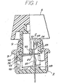
- a base member 1 is an insert-molded plastic member carrying a contact member 2, and includes a springy nail 11 and a light emitting diode (hereinafter, abbreviated as LED) supporter 12 as a single molded unit.
- a cover 3 is mounted on the base member 1 by engagement with the nail 11 so as to support a plunger member 4 for a vertical sliding movement within the cover 3.
- the plunger member 4 is upwardly biased by a reset coil spring 43 within the cover 3.
- the case 3 consists of a lower p6rtion of a square cylindrical shape, and an upper portion of a cylindrical shape through which a head portion of the plunger member 4 projects so as to be mounted by a key button 5, as illustrated in Fig. Z there is disposed a window portion 31 on an upper wall of the square cylindrical portion of the cover 3.
- the window portion 31 is normally closed by a thin plate which is molded together with the cover 3 as a single unit and easy to be broken to form a hole extending through the window portion 31 if desired.
- the LED supporter 12 is disposed to support a LED 6 on a head portion of the supporter 12.
- Fig. 3 should read that the reference numerals 14, 62, 13 and 61 are drawn to the corresponding components depicted in the right-hand of the drawing.
- a pair of terminals 61 of the LED 6 are so guided by grooves 13 that projecting portions 62 of the terminals 61 are engaged with recesses 14 formed in the grooves 13 for temporarily fixing'the LED in a position.
- the temporarily fixed LED 6 is sandwitched between the supporter 12 and an inner wall surface of the cover so as to fix the LED in its position.
- the lead terminals 61 are guided by the grooves 31 so as to extend below the base member 1, so that any additional connection terminals for the LED are not needed to be disposed on the base member 1.
- the lights emitted from the LED 6 through the window 31 are guided by a transparent member 51 buried in the key button 5 to be outwardly radiated therefrom. Since the window portion 31 is closed by the thin plate on molding, it must be broken in advance so as to receive the LED 6.
- the keyboard switch of Fig. 2 is designed for a non-illuminated switch, it has only to be modified in such a manner that the LED 6 is not employed, the key button 5 does not have the transparent member 51 and the thin plate in the window portion 31 is not broken.
- this keyboard switch is convertible with ease between illuminated and non-illuminated switches. Since the window portion 31 in such a non-illuminated switch is closed, any foreign matter, such as external dust or the like, is prevented to enter within the cover 3.
- the window portion 31 may be molded to include a hole extending therethrough.
- the plunger member 4 on its lower opposite side walls includes a pair of stub shafts 42 to be rotatably mounted by a rotary cam 71.
- the rotary cam 71 has a symmetrical configuration with respect to a centre hole 70 pierced by the shaft 42.
- the rotary cam 71 at its periphery are symmetrically provided with a pair of grooves 72 and 74 and a pair of sloping surfaces 73 and 75.
- a first stationary cam 76 having a projection 77 is mounted on a recessed step formed on the base member 1 so as to be fixed by a projection (not shown) formed on an inner wall of the cover 3 as mounted.
- a second stationary cam 32 is formed on an inner side wall surface of the cover 3 as a single molding.
- the shaft 42 is in the position P 1 .
- the cam 71 takes the position shown in two dotted lines 71a where a lower surface of the cam 71 comes in contact with an upper surface of the projection 77 of the stationary cam 76.
- the top end of the projection 77 comes in contact with the groove 74 of the rotary cam 71 and the shaft 42 comes into the position P 3 where the rotary cam 71 takes the angular position rotated by about 10 degrees as shown in the two-dotted lines 71b.
- the rotary cam 71 upwardly moves at the same angular position of about 10 degrees but is stopped by the bottom end 33 of the stationary cam 32 engaged with the upper groove 72 of the cam 71. Then, the shaft 42 locked in the position P 42 and the cam 71 takes the position shown in the two-dotted lines 71c. If the key button 5 is depressed again, the plunger member 4 is depressed downwardly and the lower sloping surface 75 comes in contact with the upper surface 77 of the stationary cam 76 because as the upper groove 72 was engaged with the bottom end 33 in the former operation, the cam 71 has been further rotated in a counterclockwise direction to a certain extent and retains the same angular position.
- the rotary cam 71 Upon further depression applied to the button 5, the rotary cam 71 further rotates counterclockwise because of the slope 75 engaged with the slope 77. Upon releasing the depression to the button 5, the plunger member 4 moves upwardly and the rotary cam 71 further rotates counterclockwise because the upper sloping surface 73 and a side wall of the cam 71 are pushed by the bottom end 33 of the second stationary cam 32, so that the rotary cam 71 returns to its original position where the shaft 42 is in the position P 1 .
- the rotary cam 71 is gradually rotated by the stationary cams 76 and 32, so that there is provided an alternate mechanism a-a push-on-and-push-off mechanism such that it is locked upon a first depression applied to the key button 5 and is unlocked upon a second depression after releasing of the first depression. It should be understood that the rotary cam 71 is tightly supported by the shaft 42 to such an extent that the cam 71 can be rotated only by the cams 76 and 32 and is hard to be rotated by any external mechanical shock to the cam 71.
- the keyboard switch is desired to be of a non- alternate mechanism type or a momentary type having no locking function
- the rotary cam 71 and/or the stationary -cam 76 have only to be omitted.
- the keyboard switch according to this embodiment can be modified from the momentary type to the alternate type.
- the first cam 76 may be molded to further include the second cam 32 so as to be mounted on the base member 1 as a single component.
- the first and second cams 76 and 32 may be modified to be formed on an inner wall surface of the plunger member 4.
- the first and the second cam 76 and 32 may be formed on an inner wall surface of the plunger member 4 and the base member 1, respectively.
- the contact member 2 consists of an arch-shaped stationary blade 21 having a pair of legs 22 and a springy movable blade 25.
- the respective blades 21 and 25 carry respective contacts 23 and 26
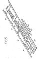
- the contact member 2 may be assembled by the following automated producing processes: In the first step, as illustrated in a section A of Fig. 5, a single metal plate 29 is stamped out to form a hoop-shaped member including the stationary blade 21 having a pair of legs 22 and a terminal 24, and the contact 23 is disposed. In the subsequent step, as illustrated in a section B of Fig. 5, a hoop-shaped member having the movable blade 25 driven to a predetermined position above the hoop-shaped plate 29 from a side direction. In advance, the movable blade 25 is formed by stamping out a metal plate, the contact 26 is disposed on the blade 25 at its free end, and a bent portion 27 is formed.
- a connecting portion of the movable blade 25 is cut off so as to form a component as illustrated in a section C of Fig. 5.
- a connecting portion 28 of the terminal blade 24 is cut off to form a component as illustrated in a section D of Fig. 5.
- such a component is separated one by one so as to form an isolated component shown in Fig. 6.
- the metal plate of Fig. 6 is inserted in a molded plastic member by an insert-molding process so as to form base member 1 as illustrated in Fig. 7.
- a peripheral frame portion of the component of Fig. 7 is cut off so as to constitute the base member 2 shown in Fig. 2.
- the legs 22 of the stationary blade 21 downwardly extend through the base member 1 to form connection terminals, and the terminal blade 24 and the blade 21 are made of a single plate so that they can be thick and solid. Therefore, the keyboard switch is easy to be mounted on a printed circuit board without deforming their connecting terminals viz. bottom ends of the blades 24 and 21. Moreover, since the switching terminal 24 is positioned between a pair of interconnected terminals 22, the keyboard switch is available for a simplified connection pattern on a printed circuit board. That is, according to an associated circuit pattern on the board, either of terminals 22 can be connected to other component on the board.
- the bent portion 27 of the movable blade 25 is pushed by a card 41 formed within the plunger member 4 so that the contacts 23 and 26 are parted each other as illustrated in Fig. 1.
- the card 41 moves downwardly upon depressing the key button 5, the card 41 slides on a surface of the portion 27 downwardly so that the springy blade 25 returns toward a left-hand direction of Fig. 1 to close the contacts 23 and 26.
- the terminals 22 and 24 make a closed circuit.
- the terminal 21 and 24 provides an opened circuit.
- the cover 3 is a molded plastic member having no opening as assembled, so that the assembled keyboard switch is protected from any external foreign matter.
- an alternate mechanism which can have a long mechanical life and provide a high electrical insulation therein because a rotary cam and of stationary cams are plastic mold members with accurate dimension and can be engaged with one another without abrasion.
- the respective components constituting the alternate mechanism are molded in highly accurate dimensions, any misoperation, such as inoperative lock and so forth, is prevented from occurring, and any adjustment on assembling is unnecessary.
- the alternate mechanism can be produced at a reduced cost. If desired, of course, some component of the alternate mechanism may be of metal.
Landscapes
- Push-Button Switches (AREA)
Applications Claiming Priority (4)
| Application Number | Priority Date | Filing Date | Title |
|---|---|---|---|
| JP19681581U JPS58101432U (ja) | 1981-12-29 | 1981-12-29 | キ−ボ−ドスイツチ |
| JP196815/81 | 1981-12-29 | ||
| JP438282A JPS58121517A (ja) | 1982-01-13 | 1982-01-13 | オルタネイト機構 |
| JP4382/82 | 1982-01-13 |
Publications (2)
| Publication Number | Publication Date |
|---|---|
| EP0083508A1 true EP0083508A1 (de) | 1983-07-13 |
| EP0083508B1 EP0083508B1 (de) | 1987-05-06 |
Family
ID=26338132
Family Applications (1)
| Application Number | Title | Priority Date | Filing Date |
|---|---|---|---|
| EP82307009A Expired EP0083508B1 (de) | 1981-12-29 | 1982-12-30 | Kontaktaufbau für einen alternierenden Schaltmechanismus |
Country Status (4)
| Country | Link |
|---|---|
| US (2) | US4495391A (de) |
| EP (1) | EP0083508B1 (de) |
| CA (1) | CA1237751A (de) |
| DE (1) | DE3276279D1 (de) |
Cited By (4)
| Publication number | Priority date | Publication date | Assignee | Title |
|---|---|---|---|---|
| EP0163414A1 (de) * | 1984-04-25 | 1985-12-04 | Minnesota Mining And Manufacturing Company | Fassung zum Testen von integrierten Schaltkreisen |
| CN101707164B (zh) * | 2009-09-22 | 2012-06-27 | 厦门宏发电声股份有限公司 | 一种电磁继电器的接触系统 |
| WO2014154439A1 (de) * | 2013-03-28 | 2014-10-02 | Zf Friedrichshafen Ag | Tastenmodul für eine taste einer tastatur und verfahren zum herstellen eines tastenmoduls für eine taste einer tastatur |
| DE102017106283A1 (de) | 2017-03-23 | 2018-09-27 | Cherry Gmbh | Tastenmodul für eine Tastatur und Verfahren zum Herstellen eines Tastenmoduls für eine Tastatur |
Families Citing this family (16)
| Publication number | Priority date | Publication date | Assignee | Title |
|---|---|---|---|---|
| CA1270876A (en) * | 1984-03-22 | 1990-06-26 | Sueaki Honda | Push-button lever contact switch |
| EP0188215B1 (de) * | 1985-01-08 | 1992-08-05 | Omron Tateisi Electronics Co. | Drucktastenschalter |
| DE3716288A1 (de) * | 1987-01-15 | 1988-07-28 | Itw Ateco Gmbh | Schliessvorrichtung fuer eine einen hohlraum abschliessende klappe oder dergleichen |
| US4755641A (en) * | 1987-04-20 | 1988-07-05 | Switchcraft, Inc. | Pawl controlled switch |
| US4771141A (en) * | 1987-07-31 | 1988-09-13 | Zanxx, Inc. | Push-push electrical switch |
| US5043545A (en) * | 1988-06-02 | 1991-08-27 | Omron Tateisi Electronics Co. | Microswitch |
| US4996401A (en) * | 1989-06-29 | 1991-02-26 | Prince Corporation | Switch |
| US5145059A (en) * | 1989-06-29 | 1992-09-08 | Prince Corporation | Switch |
| ITTO20020008U1 (it) * | 2002-01-18 | 2003-07-18 | Urmet Domus Spa | ,,contattore a pulsante per l'attivazione di segnali di chiamata in pulsantiere,, |
| US20070024588A1 (en) * | 2005-07-26 | 2007-02-01 | Yin Memphis Z | Keyboard lighting device |
| US7375300B2 (en) * | 2005-09-08 | 2008-05-20 | Illinois Tool Works Inc. | Switch assembly |
| DE102005053792B4 (de) * | 2005-11-09 | 2009-02-19 | Diehl Ako Stiftung & Co. Kg | Kapazitiver Berührungsschalter |
| DE202006011803U1 (de) * | 2006-08-01 | 2006-09-28 | Cherry Gmbh | Tastenknopf |
| JP5857988B2 (ja) * | 2013-03-08 | 2016-02-10 | オムロン株式会社 | スイッチ |
| TWI703600B (zh) * | 2016-10-14 | 2020-09-01 | 美商伊利諾工具工程公司 | 用於閂鎖之裝置與方法以及包括此閂鎖裝置之切換系統 |
| FR3058550B1 (fr) * | 2016-11-08 | 2021-02-12 | Schneider Electric Ind Sas | Dispositif de signalisation visuelle pour organe de commande et/ou de visualisation |
Citations (3)
| Publication number | Priority date | Publication date | Assignee | Title |
|---|---|---|---|---|
| US3691333A (en) * | 1971-03-19 | 1972-09-12 | Illinois Tool Works | Alternate action mechanism |
| US3770923A (en) * | 1972-01-14 | 1973-11-06 | Cherry Electrical Prod | Alternate-action switch actuator with pawl stop plate also providing a guide for stroke-control means |
| DE2816185A1 (de) * | 1978-04-14 | 1979-10-18 | Kostal Fa Leopold | Rasteinrichtung fuer einen drucktastenschalter |
Family Cites Families (16)
| Publication number | Priority date | Publication date | Assignee | Title |
|---|---|---|---|---|
| US1352889A (en) * | 1919-04-29 | 1920-09-14 | Galileo Gallo | Switch |
| US2749415A (en) * | 1952-12-04 | 1956-06-05 | James E Davis | Switch operating mechanism |
| US2890387A (en) * | 1955-01-18 | 1959-06-09 | Sylvania Electric Prod | Automobile headlight control system |
| DE1665615B1 (de) * | 1966-04-25 | 1971-12-16 | Siemens Ag | Wahlweise zusammensetzbare Steckfassung |
| GB1171082A (en) * | 1968-03-22 | 1969-11-19 | Frederick Preston Willcox | Electrical Switches Device. |
| US3619532A (en) * | 1969-09-17 | 1971-11-09 | Electrohome Ltd | Self-aligning contact for switch |
| DE2031025A1 (de) * | 1970-06-23 | 1971-12-30 | Siemens Ag | Kontaktfedersatz |
| US3715545A (en) * | 1971-06-18 | 1973-02-06 | Cherry Electrical Prod | Momentary push button switch with improved non-conductive cam for normally retaining movable leaf spring contacts in a non-operative position |
| DE2145584A1 (de) * | 1971-09-13 | 1973-03-22 | Philips Patentverwaltung | Verfahren zum herstellen eines kontaktschalters mit mehreren parallel zueinander angeordneten kontaktfedern |
| DE2212180A1 (de) * | 1972-03-14 | 1973-09-20 | Westfael Kupfer & Messing | Elektrischer schalter |
| US4096368A (en) * | 1976-07-08 | 1978-06-20 | Cutler-Hammer, Inc. | Pushbutton switch |
| JPS5726266Y2 (de) * | 1976-07-15 | 1982-06-08 | ||
| SE402654B (sv) * | 1976-12-21 | 1978-07-10 | Ericsson Telefon Ab L M | Tryckknappsomkopplare for anvendning vid pa ett kretskort anordnade stromkretsar |
| DE2848567C2 (de) * | 1977-12-30 | 1985-08-29 | Alps Electric Co., Ltd., Tokio/Tokyo | Druckknopfschalter mit einem verstellbaren Schalthebel |
| GB2080029B (en) * | 1980-07-08 | 1984-04-18 | Philips Electronic Associated | Push button switch |
| US4361743A (en) * | 1981-03-06 | 1982-11-30 | Stackpole Components Company | Lost motion keyswitch |
-
1982
- 1982-12-29 CA CA000418672A patent/CA1237751A/en not_active Expired
- 1982-12-29 US US06/454,270 patent/US4495391A/en not_active Expired - Fee Related
- 1982-12-30 EP EP82307009A patent/EP0083508B1/de not_active Expired
- 1982-12-30 DE DE8282307009T patent/DE3276279D1/de not_active Expired
-
1984
- 1984-07-16 US US06/631,199 patent/US4647742A/en not_active Expired - Fee Related
Patent Citations (3)
| Publication number | Priority date | Publication date | Assignee | Title |
|---|---|---|---|---|
| US3691333A (en) * | 1971-03-19 | 1972-09-12 | Illinois Tool Works | Alternate action mechanism |
| US3770923A (en) * | 1972-01-14 | 1973-11-06 | Cherry Electrical Prod | Alternate-action switch actuator with pawl stop plate also providing a guide for stroke-control means |
| DE2816185A1 (de) * | 1978-04-14 | 1979-10-18 | Kostal Fa Leopold | Rasteinrichtung fuer einen drucktastenschalter |
Non-Patent Citations (1)
| Title |
|---|
| I.B.M. Technical Disclosure Bulletin, vol. 19, no. 4, September 1976, pages 1371-1372, NEW YORK (USA); * |
Cited By (7)
| Publication number | Priority date | Publication date | Assignee | Title |
|---|---|---|---|---|
| EP0163414A1 (de) * | 1984-04-25 | 1985-12-04 | Minnesota Mining And Manufacturing Company | Fassung zum Testen von integrierten Schaltkreisen |
| CN101707164B (zh) * | 2009-09-22 | 2012-06-27 | 厦门宏发电声股份有限公司 | 一种电磁继电器的接触系统 |
| WO2014154439A1 (de) * | 2013-03-28 | 2014-10-02 | Zf Friedrichshafen Ag | Tastenmodul für eine taste einer tastatur und verfahren zum herstellen eines tastenmoduls für eine taste einer tastatur |
| AU2014243387B2 (en) * | 2013-03-28 | 2016-09-15 | Cherry Gmbh | Key module for a keyboard key and method for producing a key module for a keyboard key |
| US9728350B2 (en) | 2013-03-28 | 2017-08-08 | Cherry Gmbh | Illuminated key module |
| RU2645756C2 (ru) * | 2013-03-28 | 2018-02-28 | Черри ГмбХ | Модуль клавиши для клавиши клавиатуры и способ изготовления модуля клавиши для клавиши клавиатуры |
| DE102017106283A1 (de) | 2017-03-23 | 2018-09-27 | Cherry Gmbh | Tastenmodul für eine Tastatur und Verfahren zum Herstellen eines Tastenmoduls für eine Tastatur |
Also Published As
| Publication number | Publication date |
|---|---|
| DE3276279D1 (en) | 1987-06-11 |
| CA1237751A (en) | 1988-06-07 |
| US4495391A (en) | 1985-01-22 |
| US4647742A (en) | 1987-03-03 |
| EP0083508B1 (de) | 1987-05-06 |
Similar Documents
| Publication | Publication Date | Title |
|---|---|---|
| US4495391A (en) | Alternate on-off switch mechanism | |
| US5055642A (en) | Push button switch | |
| US4169974A (en) | Push operated momentary switch | |
| US4417115A (en) | Switch actuating assembly having improved cams and plural modes | |
| US20140190812A1 (en) | Push switch | |
| US3774000A (en) | Lever operated electrical switches | |
| US4684775A (en) | Miniature push button switch with coil spring movable contact | |
| US4395609A (en) | Cam operated dual switch assembly | |
| EP0101958A2 (de) | Tastenschalter | |
| JP3174908B2 (ja) | 多方向揺動型電子部品 | |
| KR860000839Y1 (ko) | 슬라이드 스위치 | |
| JPH11353976A (ja) | 照明機能付き回転式電子部品 | |
| JPH0526652Y2 (de) | ||
| CA1254603A (en) | Alternate off-on switch | |
| US4514608A (en) | Locking type pushbutton switch | |
| EP0122642B1 (de) | Beleuchtete Display-Anordnung | |
| US5076426A (en) | Snap action switch | |
| KR0152293B1 (ko) | 푸시버튼 스위치 | |
| US5006680A (en) | Snap action switch | |
| US4306132A (en) | Electrical switches | |
| US4531032A (en) | Locking type pushbutton switch | |
| EP0184815B1 (de) | Schnappmechanismus | |
| GB2225166A (en) | Push-button switch | |
| EP0344800A3 (de) | Mikroschalter | |
| JPS6328815Y2 (de) |
Legal Events
| Date | Code | Title | Description |
|---|---|---|---|
| PUAI | Public reference made under article 153(3) epc to a published international application that has entered the european phase |
Free format text: ORIGINAL CODE: 0009012 |
|
| 17P | Request for examination filed |
Effective date: 19830128 |
|
| AK | Designated contracting states |
Designated state(s): DE FR GB IT |
|
| GRAA | (expected) grant |
Free format text: ORIGINAL CODE: 0009210 |
|
| AK | Designated contracting states |
Kind code of ref document: B1 Designated state(s): DE FR GB IT |
|
| REF | Corresponds to: |
Ref document number: 3276279 Country of ref document: DE Date of ref document: 19870611 |
|
| ET | Fr: translation filed | ||
| ITF | It: translation for a ep patent filed | ||
| PLBE | No opposition filed within time limit |
Free format text: ORIGINAL CODE: 0009261 |
|
| STAA | Information on the status of an ep patent application or granted ep patent |
Free format text: STATUS: NO OPPOSITION FILED WITHIN TIME LIMIT |
|
| 26N | No opposition filed | ||
| PGFP | Annual fee paid to national office [announced via postgrant information from national office to epo] |
Ref country code: FR Payment date: 19901212 Year of fee payment: 9 |
|
| PGFP | Annual fee paid to national office [announced via postgrant information from national office to epo] |
Ref country code: GB Payment date: 19901217 Year of fee payment: 9 |
|
| ITTA | It: last paid annual fee | ||
| PGFP | Annual fee paid to national office [announced via postgrant information from national office to epo] |
Ref country code: DE Payment date: 19901231 Year of fee payment: 9 |
|
| PG25 | Lapsed in a contracting state [announced via postgrant information from national office to epo] |
Ref country code: GB Effective date: 19911230 |
|
| GBPC | Gb: european patent ceased through non-payment of renewal fee | ||
| PG25 | Lapsed in a contracting state [announced via postgrant information from national office to epo] |
Ref country code: FR Effective date: 19920831 |
|
| PG25 | Lapsed in a contracting state [announced via postgrant information from national office to epo] |
Ref country code: DE Effective date: 19920901 |
|
| REG | Reference to a national code |
Ref country code: FR Ref legal event code: ST |