EP0083569A1 - Verfolgungssteuerungsgerät mittels Wendungen in quergeneigter Lage gemäss Breitwinkel mit Schwerkraftausgleich - Google Patents
Verfolgungssteuerungsgerät mittels Wendungen in quergeneigter Lage gemäss Breitwinkel mit Schwerkraftausgleich Download PDFInfo
- Publication number
- EP0083569A1 EP0083569A1 EP83300010A EP83300010A EP0083569A1 EP 0083569 A1 EP0083569 A1 EP 0083569A1 EP 83300010 A EP83300010 A EP 83300010A EP 83300010 A EP83300010 A EP 83300010A EP 0083569 A1 EP0083569 A1 EP 0083569A1
- Authority
- EP
- European Patent Office
- Prior art keywords
- signal
- load factor
- lift load
- aircraft
- angle
- Prior art date
- Legal status (The legal status is an assumption and is not a legal conclusion. Google has not performed a legal analysis and makes no representation as to the accuracy of the status listed.)
- Withdrawn
Links
- 230000005484 gravity Effects 0.000 title description 4
- 230000001133 acceleration Effects 0.000 claims description 8
- 230000001419 dependent effect Effects 0.000 claims description 6
- 238000010586 diagram Methods 0.000 description 17
- 239000013598 vector Substances 0.000 description 15
- 238000000034 method Methods 0.000 description 8
- RZVHIXYEVGDQDX-UHFFFAOYSA-N 9,10-anthraquinone Chemical compound C1=CC=C2C(=O)C3=CC=CC=C3C(=O)C2=C1 RZVHIXYEVGDQDX-UHFFFAOYSA-N 0.000 description 7
- 230000009897 systematic effect Effects 0.000 description 6
- 238000012546 transfer Methods 0.000 description 4
- 230000004044 response Effects 0.000 description 3
- 238000006467 substitution reaction Methods 0.000 description 3
- 238000012937 correction Methods 0.000 description 2
- 230000008569 process Effects 0.000 description 2
- 230000001052 transient effect Effects 0.000 description 2
- 230000008859 change Effects 0.000 description 1
- 230000008878 coupling Effects 0.000 description 1
- 238000010168 coupling process Methods 0.000 description 1
- 238000005859 coupling reaction Methods 0.000 description 1
- 238000013461 design Methods 0.000 description 1
- 230000000694 effects Effects 0.000 description 1
- 238000012545 processing Methods 0.000 description 1
- 238000000926 separation method Methods 0.000 description 1
Images


Classifications
-
- G—PHYSICS
- G05—CONTROLLING; REGULATING
- G05D—SYSTEMS FOR CONTROLLING OR REGULATING NON-ELECTRIC VARIABLES
- G05D1/00—Control of position, course, altitude or attitude of land, water, air or space vehicles, e.g. using automatic pilots
- G05D1/10—Simultaneous control of position or course in three dimensions
- G05D1/101—Simultaneous control of position or course in three dimensions specially adapted for aircraft
Definitions
- This invention relates to bank-to-turn pursuit controllers for fixed wing aircraft and missiles, and more particularly, to such a pursuit controller capable of providing rapid and precise pursuit steering control for substantially lift supported vehicles operating in the presence of a gravitational field.
- a system for accomplishing bank-to-turn pursuit steering of an aircraft includes means for generating a lift-load factor attenuation signal and means for generating first and second signals representing the components of commanded path turn rate compensated for gravitational path turn rate, the first and second signals being dependent upon the lift load factor attenuation signal. Also included are means for generating a lift load factor command signal which is less than or equal to a predetermined upper-limit, the generating means having inputs of the first and second signals. Also included are means for generating a bank angle command signal appropriate for use with the lift load factor command signal, the generating means having inputs of the first and second signals.
- first and second signals representing the components of commanded path turn rate compensated for gravitational path turn rate
- first signal 1 representing the component of commanded path turn rate in the transverse plane
- second signal 2 representing the component of commanded path turn rate in the vertical plane as compensated for gravitational path turn rate 8.
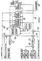
- First and second signals 1 and 2 are dependent upon a lift load factor attenuation signal 3, which is generated in a systematic adjuster 15.
- Means are provided for generating a lift load factor command signal 16 and such may take the form of lift load factor command generator 14 which has inputs of first signal 1 and second signal 2 as well as signals representing aircraft speed 10, gravitational acceleration constant 11 and an enabling signal 19.
- Lift load factor command signal 16 is less than or equal to a predetermined upper limit 9.
- Means are also provided for generating a bank angle command signal 17 appropriate for use with the lift load factor command signal 16, and such may take the form of bank angle command generator 18, which has inputs of the first and second signals 1 and 2 respectively, and the enabling signal 19.
- Means are provided for generating a trial lift load factor command signal 13 which takes the form of trial lift factor command generator 12 having inputs from the first and second signals 1 and 2. Means are also provided for comparing the trial lift load factor command signal 13 with a predetermined upper limit 9 and for modifying lift load factor attenuation signal 3 when signal 13 exceeds the predetermined upper limit and such may take the form of systematic adjuster 15.
- first and second signals represent the components, in a roll stabilized axis system, of commanded path turn rate in the transverse and vertical planes, respectively.
- the vertical and transverse planes containing the commanded path turn rate components are each understood to contain the aircraft velocity vector, and the transverse plane is further understood to be perpendicular to said vertical plane.
- the terms "path turn rate” and "angular velocity of the aircraft velocity vector” are interchangeable.
- the aircraft direction of travel is understood to have the direction and sense of the aircraft velocity vector.
- the aircraft is steered along a path such that the vertical path angle rate of change is proportional to the difference between the vertical path angle and the elevation of the line of sight from the aircraft to the target as determined in a vertical plane, and path turn rate in the transverse plane bears the same proportional relationship to the bearing of the target with respect to the aircraft direction of travel as determined in the horizontal plane.
- first signal 1 representing the component of commanded path turn rate in the transverse plane is formed as the product of: a signal 5 representing target bearing angle between a vertical plane containing the aircraft direction of travel and the vertical plane containing the line of sight from the aircraft to the target; a predetermined dynamic performance parameter 4; a signal 6 representing the cosine of vertical path angle; and the lift load factor attenuation signal 3.
- Second signal 2 representing the component of commanded path turn rate in the vertical plane as compensated for gravitational path turn rate is formed as the product of: a signal 7 representing the angular difference between target elevation as determined in a vertical plane containing the aircraft and the target, and the elevation of the aircraft direction of travel as determined in a vertical plane; the predetermined dynamic performance parameter 4; and the lift load factor attenuation signal 3; combined with a signal 8 representing gravitational path turn rate.
- first and second signals 101 and 102 of Figure 10 representing the components of commanded path turn rate in the transverse and vertical planes, respectively; the aircraft is steered such that the aircraft direction of travel is commanded directly toward the target point at every instant of time.
- first signal 101 representing the component of commanded path turn rate in the transverse plane is formed as the product of: a signal 121 representing the sine of target bearing angle between a vertical plane containing the aircraft direction of travel and a vertical plane containing the aircraft and the target; a signal 122 representing the cosine of elevation angle for the line of sight from the aircraft to the target as determined in the vertical plane containing said line of sight; a signal 91 representing the ratio of the magnitude of an angle between the aircraft direction of travel and the line of sight from the aircraft to the sine of said angle; a predetermined dynamic performance parameter 4; and the lift load factor attenuation signal 103.
- Second signal 102 representing the component of commanded path turn rate in the vertical plane as compensated for gravitational path turn rate is formed as the product of: a third signal 123; the signal 91 representing the ratio of the magnitude of the angle between the aircraft direction of travel and the line of sight from the aircraft to the target to the sine of said angle; the predetermined dynamic performance parameter 4; and the lift load factor attenuation signal 103; combined with a signal 8 representing gravitational path turn rate.
- the third signal 123 is the product of the signal 6 representing the cosine of the aircraft vertical path angle, and a signal 124 representing the sine of elevation angle for the line of sight from the aircraft to the target as determined in the vertical plane containing said line of sight, combined with the product of a signal 125 representing the sine of the aircraft vertical path angle, the signal 122 representing the cosine of elevation angle for the line of sight from the aircraft to the target as determined in the vertical plane containing said line of sight, and a signal 126 representing the cosine of target bearing angle between a vertical plane containing the aircraft direction of travel and the vertical plane containing the aircraft and the target.
- Dynamic performance parameter 4 determines the maximum small signal bandwidth of the pursuit steering controller. Its value is free to be chosen for each particular application.
- Lift load factor attenuation signal, 3, in Figure 1 and 103 in Figure 10 takes on values between zero and one to satisfy the constraint that the positive lift load factor command, 16 in Figure 1 and 116 in Figure 10, not exceed predetermined upper limit 9. This upper limit value is free to be chosen for each particular application.
- signal 10 representing vehicle speed and the gravitational acceleration constant 11 and first and second signals 1 and 2 are combined in the trial lift load factor command generator 12 to obtain the trial lift load factor command signal 13.
- the value used for the lift load factor attenuation signal 3 is unity as inputted at 20 if that value results in a trial lift load factor command signal 13 which is less than or equal the predetermined upper limit 9. If the trial lift load factor command signal 13 exceeds the upper limit 9 for a lift load factor attenuation signal of 1.0, then a lesser positive value for the lift load factor attenuation signal 3 is found by a systematic adjustment procedure in systematic adjuster 15 which results in a trial lift load factor command signal 13 equal to the predetermined upper limit 9.
- the final value of the trial lift load factor command signal 13 obtained in the manner above is used as the actual lift load factor command signal 16.
- the corresponding final values for first and second signals 1 and 2 are used to obtain the bank angle command signal 17. That is, the bank command signal 17 is determined by bank angle command generator 18 such that the transverse component of commanded lift load factor and first signal 1 are in the same proportion to one another as are the component of commanded lift load factor which lies in the vertical plane containing the vehicle direction of travel and second signal 2.
- aircraft body-fixed axes and aircraft flight path axes The relationship between aircraft body-fixed axes and aircraft flight path axes is described in terms of the aircraft angles of attack, ⁇ , and sideslip, ⁇ . These axis systems and angles are shown in relation to an aircraft in Figure 2.
- the orientation of the aircraft flight path axis system relative to gravitational vertical, g, is established by aircraft bank angle, 4, and vertical path (or elevation) angle, ⁇ . Orientation of the aircraft flight path axes to the gravitational vertical is also shown in Figure 2.
- the normal lift load factor, (1/g) times normal acceleration is:
- transfer functions relating the bearing and elevation to the absolute target angles are: These transfer functions establish the bandwidth of the control process as K radians/unit time, and the independence of bearing and elevation control.
- the bank angle which solves the two equations immediately above can be regarded as a bank angle command, ⁇ c .
- the signal 17 representing the bank angle command, ⁇ c is generated by the bank angle command generator 18 in the block diagram of Figure 1.
- Figure 6 is a schematic diagram representing a circuit for generating the bank angle command signal 17 upon receipt of the enable signal 19.
- the nonlinear function 61 in Figure 6 generates an output signal 62 representing the angle whose tangent is represented by the input signal 63.
- N ZC a lift load factor command
- the signal 16 representing lift load factor command, N zc is generated by the lift load factor command generator 14 in the block diagram of Figure 1.
- Figure 5 is a schematic diagram representing a circuit which may be used for generating the lift load factor command signal 16 upon receipt of the enable signal 19. In this application of the circuit, the output signal 51 is the signal denoted by 16 in Figure 1.
- N Z max A predetermined upper limit, can be imposed upon N zc by means of the lift load factor attenuation parameter, k.
- N ZC to be a function of k
- N ZC (k) N ZC (k)
- ⁇ c a function of k
- ⁇ c (k) N ZC (k)
- a circuit which may be used for generating the lift load factor attenuation signal 3 (representing the lift load factor attenuation parameter, k) by the direct computation method is shown in the schematic diagram of Figure 8.
- the circuit of Figure 8 replaces items 12, 13, 15, and 20 in the block diagram of Figure 1, and the enable signal 19 is always set.
- the bank angle command, ⁇ c (k), is then computed for the above value of k, and the lift load factor command, Nzc(k), is less than or equal to N z max.
- Target angle, T be the magnitude of the angle between v and t.
- Target angle, T is where T has two-quadrant validity in consideration of the sign of v . t .
- Target angle may also be represented as a vector, T, given by:
- Aircraft flight path axis components of T are as may be verified by evaluating the vector cross-and dot- product components using a value for the scale factor, F, given by:
- a signal 91 representing the scale factor, F may be generated by the circuit represented in the schematic diagram of Figure 9.
- the generated signal 91 is an input to the block diagram shown in Figure 10.
- the nonlinear function 92 in Figure 9 generates an output signal 93 representing the angle whose sine is represented by the input signal 94.
- aircraft velocity vector pitch and yaw rate commands are selected such that and then the aircraft velocity vector turn rate command is in the desired turn plane. Consequently the aircraft velocity vector is commanded directly toward the target at every instant of time.
- This transfer function establishes the bandwidth of the control process as K radians/unit time.
- the signals 116 and 117, respectively, of Figure 10 representing lift load factor command, N , and bank angle command, c, are generated by the lift load factor command generator 114 and the bank angle command generator 118 of Figure 10.
- Figure 5 represents a circuit which may be used for generating the lift load factor command signal 116 upon receipt of the enable signal 119.
- signals 1, 2, and 51 in Figure 5 are replaced by signals 101, 102, and 116 respectively.
- the circuit of Figure 6 may be used for generating the bank angle command signal 117 upon receipt of the enable signal 119.
- signals 1, 2, and 17 in Figure 6 are replaced by signals 101, 102, and 117 respectively.
- N z max' the enable signal 119 in Figure 10 is set. Otherwise, the enable signal is clear.
- FIG. 8 A circuit useful for generating the lift load factor attenuation signal 103 (representing the lift load factor attenuation parameter, k) by the direct computation method is shown in Figure 8.
- signal 3 in Figure 8 is replaced by signal 103
- signals 82 and 83 in Figure 8 are replaced by signals representing quantities a and b,respectively,as defined by the above equations.
- the circuit of Figure 8 as described above, replaces items 112, 113, 115 and 20 in the block diagram of Figure 10, and the enable signal 119 is always set.
- the resulting commands can be coupled to the aircraft flight control system according to the following equations:
- the lift load factor command, N zc may be used as it stands. However, with additional processing, a modified lift load factor command, N*, zc is obtained which minimizes the path turn rate error during the bank angle, 4, response transient.
- the modified lift load factor command, N * zc can be used in place of the (unmodified) lift load factor command, N , in the above equations describing command.coupling to the aircraft flight control system. This feature has significant appeal for applications where precise path control is required.
- the effect is to unload the aircraft substantially during the bank angle response transient while large changes in aircraft bank angle are commanded.
- the quantities in parentheses are the components of path turn rate in a roll stabilized axis system. The differences are between commanded and actual turn rate components. If the aircraft is flown in a coordinated manner and if the pitch rate response, Q, to the modified lift load factor command, N * zc , is immediate then: zc
- the signal 71 representing the modified lift load factor command may be generated as shown in Figure 7. This signal is dependent upon signals 16, 17 and 72 respectively representing the (unmodified) lift load factor command, N zc , bank angle command, ⁇ c , and aircraft bank angle, 4.
- the nonlinear function element 73 implements the cosine of the bank angle error function for a range of error magnitude from zero to ninety degrees.
- the signal representing modified lift load factor may be generated as shown in Figure 7, but using alternative signals 116 and 117 in place of signals 16 and 17 respectively representing (unmodified) lift load factor command, N zc , and bank angle command, ⁇ c.
Landscapes
- Engineering & Computer Science (AREA)
- Aviation & Aerospace Engineering (AREA)
- Radar, Positioning & Navigation (AREA)
- Remote Sensing (AREA)
- Physics & Mathematics (AREA)
- General Physics & Mathematics (AREA)
- Automation & Control Theory (AREA)
- Control Of Position, Course, Altitude, Or Attitude Of Moving Bodies (AREA)
Applications Claiming Priority (2)
| Application Number | Priority Date | Filing Date | Title |
|---|---|---|---|
| US336910 | 1982-01-04 | ||
| US06/336,910 US4511972A (en) | 1982-01-04 | 1982-01-04 | Large angle, gravity compensated, bank-to-turn pursuit controller |
Publications (1)
| Publication Number | Publication Date |
|---|---|
| EP0083569A1 true EP0083569A1 (de) | 1983-07-13 |
Family
ID=23318230
Family Applications (1)
| Application Number | Title | Priority Date | Filing Date |
|---|---|---|---|
| EP83300010A Withdrawn EP0083569A1 (de) | 1982-01-04 | 1983-01-04 | Verfolgungssteuerungsgerät mittels Wendungen in quergeneigter Lage gemäss Breitwinkel mit Schwerkraftausgleich |
Country Status (4)
| Country | Link |
|---|---|
| US (1) | US4511972A (de) |
| EP (1) | EP0083569A1 (de) |
| JP (1) | JPS58156497A (de) |
| AU (1) | AU556559B2 (de) |
Cited By (3)
| Publication number | Priority date | Publication date | Assignee | Title |
|---|---|---|---|---|
| FR2658636A1 (fr) * | 1990-02-22 | 1991-08-23 | Sextant Avionique | Procede de pilotage d'un aeronef en vol a tres basse altitude. |
| CN104197792A (zh) * | 2014-08-22 | 2014-12-10 | 哈尔滨工业大学 | 一类多平衡点饱和切换系统的离散增益调度控制器设计方法及实现btt导弹控制的方法 |
| US20220221878A1 (en) * | 2021-01-14 | 2022-07-14 | Bell Textron Inc. | Intelligent aircraft and rotorcraft load factor and stall protection |
Families Citing this family (3)
| Publication number | Priority date | Publication date | Assignee | Title |
|---|---|---|---|---|
| US5062583A (en) * | 1990-02-16 | 1991-11-05 | Martin Marietta Corporation | High accuracy bank-to-turn autopilot |
| JP3645038B2 (ja) * | 1996-07-05 | 2005-05-11 | 富士重工業株式会社 | 航空機の飛行制御装置 |
| KR102339273B1 (ko) * | 2017-08-17 | 2021-12-13 | 배 시스템즈 인포메이션 앤드 일렉트로닉 시스템즈 인티크레이션, 인크. | 레이트 기반 자동조종을 위한 gbias |
Citations (6)
| Publication number | Priority date | Publication date | Assignee | Title |
|---|---|---|---|---|
| US2649264A (en) * | 1947-03-15 | 1953-08-18 | Sperry Corp | Flight control system |
| US2816723A (en) * | 1954-11-16 | 1957-12-17 | Hughes Aircraft Co | Aircraft guidance roll compensator |
| US2883127A (en) * | 1953-06-05 | 1959-04-21 | Bendix Aviat Corp | Turn control for automatic pilot systems |
| GB821519A (en) * | 1955-10-25 | 1959-10-07 | Mini Of Supply | Improvements in or relating to automatic pilot apparatus |
| US2932472A (en) * | 1957-09-11 | 1960-04-12 | Gen Electric | Automatic turn compensator for aircraft |
| US3550884A (en) * | 1967-02-02 | 1970-12-29 | Bodenseewerk Geraetetech | Autopilot |
Family Cites Families (11)
| Publication number | Priority date | Publication date | Assignee | Title |
|---|---|---|---|---|
| US4111382A (en) * | 1963-07-24 | 1978-09-05 | The United States Of America As Represented By The Secretary Of The Navy | Apparatus for compensating a ballistic missile for atmospheric perturbations |
| DE1531407A1 (de) * | 1967-07-25 | 1969-10-09 | Bodensee Fluggeraete | Flugregler |
| US4019702A (en) * | 1975-11-13 | 1977-04-26 | The Boeing Company | Method and apparatus for guiding a jet aircraft in a noise-abated post-takeoff climb |
| US4114842A (en) * | 1977-03-28 | 1978-09-19 | Sperry Rand Corporation | Acceleration limited preselect altitude capture and control |
| US4234142A (en) * | 1978-06-08 | 1980-11-18 | The United States Of America As Represented By The Secretary Of The Navy | High angle-of-attack missile control system for aerodynamically controlled missiles |
| US4254465A (en) * | 1978-08-03 | 1981-03-03 | Dynamic Sciences International, Inc. | Strap-down attitude and heading reference system |
| US4357663A (en) * | 1979-12-03 | 1982-11-02 | The Boeing Company | Method and apparatus for aircraft pitch and thrust axes control |
| US4312039A (en) * | 1980-01-24 | 1982-01-19 | Sperry Corporation | Transient free synchronization system |
| US4343035A (en) * | 1980-04-14 | 1982-08-03 | Tanner Walter E | Heading reference system |
| US4377848A (en) * | 1980-10-16 | 1983-03-22 | Sperry Corporation | Altitude capture mode for aircraft automatic flight control system |
| US4392203A (en) * | 1981-03-30 | 1983-07-05 | United Technologies Corporation | Aircraft coordinated turn with lagged roll rate |
-
1982
- 1982-01-04 US US06/336,910 patent/US4511972A/en not_active Expired - Fee Related
- 1982-12-29 JP JP57234876A patent/JPS58156497A/ja active Pending
- 1982-12-30 AU AU91917/82A patent/AU556559B2/en not_active Ceased
-
1983
- 1983-01-04 EP EP83300010A patent/EP0083569A1/de not_active Withdrawn
Patent Citations (6)
| Publication number | Priority date | Publication date | Assignee | Title |
|---|---|---|---|---|
| US2649264A (en) * | 1947-03-15 | 1953-08-18 | Sperry Corp | Flight control system |
| US2883127A (en) * | 1953-06-05 | 1959-04-21 | Bendix Aviat Corp | Turn control for automatic pilot systems |
| US2816723A (en) * | 1954-11-16 | 1957-12-17 | Hughes Aircraft Co | Aircraft guidance roll compensator |
| GB821519A (en) * | 1955-10-25 | 1959-10-07 | Mini Of Supply | Improvements in or relating to automatic pilot apparatus |
| US2932472A (en) * | 1957-09-11 | 1960-04-12 | Gen Electric | Automatic turn compensator for aircraft |
| US3550884A (en) * | 1967-02-02 | 1970-12-29 | Bodenseewerk Geraetetech | Autopilot |
Cited By (6)
| Publication number | Priority date | Publication date | Assignee | Title |
|---|---|---|---|---|
| FR2658636A1 (fr) * | 1990-02-22 | 1991-08-23 | Sextant Avionique | Procede de pilotage d'un aeronef en vol a tres basse altitude. |
| EP0453327A1 (de) * | 1990-02-22 | 1991-10-23 | Sextant Avionique S.A. | Methode zur Lenkung eines Flugzeuges im Tiefflug |
| CN104197792A (zh) * | 2014-08-22 | 2014-12-10 | 哈尔滨工业大学 | 一类多平衡点饱和切换系统的离散增益调度控制器设计方法及实现btt导弹控制的方法 |
| CN104197792B (zh) * | 2014-08-22 | 2015-10-07 | 哈尔滨工业大学 | 一类多平衡点饱和切换系统的离散增益调度控制器设计方法及实现btt导弹控制的方法 |
| US20220221878A1 (en) * | 2021-01-14 | 2022-07-14 | Bell Textron Inc. | Intelligent aircraft and rotorcraft load factor and stall protection |
| US11733714B2 (en) * | 2021-01-14 | 2023-08-22 | Textron Innovations Inc. | Intelligent aircraft and rotorcraft load factor and stall protection |
Also Published As
| Publication number | Publication date |
|---|---|
| AU9191782A (en) | 1983-07-14 |
| US4511972A (en) | 1985-04-16 |
| JPS58156497A (ja) | 1983-09-17 |
| AU556559B2 (en) | 1986-11-06 |
Similar Documents
| Publication | Publication Date | Title |
|---|---|---|
| Bezick et al. | Guidance of a homing missile via nonlinear geometric control methods | |
| CN110347170B (zh) | 可重复使用运载器再入段鲁棒容错制导控制系统及工作方法 | |
| Bugajski et al. | Nonlinear control law with application to high angle-of-attack flight | |
| Kato et al. | An interpretation of airplane general motion and contol as inverse problem | |
| Brinker et al. | Stability and flying qualities robustness of a dynamic inversion aircraft control law | |
| Singh et al. | Adaptive control of feedback linearizable nonlinear systems with application to flight control | |
| Kluever | Feedback control for spacecraft rendezvous and docking | |
| US5141177A (en) | Model following control system | |
| US3333795A (en) | Flare computer | |
| US5062583A (en) | High accuracy bank-to-turn autopilot | |
| US4511972A (en) | Large angle, gravity compensated, bank-to-turn pursuit controller | |
| US4590567A (en) | Large angle, gravity compensated, bank-to-turn pursuit controller | |
| CN113110511A (zh) | 一种基于广义模糊双曲模型的智能船舶航向控制方法 | |
| Greensite | Analysis and design of space vehicle flight control systems. volume vii-attitude control during launch | |
| Ohno et al. | Robust flight control law design for an automatic landing flight experiment | |
| JP3028888B2 (ja) | オートパイロット装置 | |
| Rusnak et al. | Improving the performance of existing missile autopilot using simple adaptive control | |
| Choi et al. | Dynamic control allocation for shaping spacecraft attitude control command | |
| US4266743A (en) | Pitch attitude stabilization system utilizing engine pressure ratio feedback signals | |
| US3540678A (en) | Method of and apparatus for controlling the transverse acceleration and roll damping of steerable aerodynamic bodies | |
| Taylor et al. | Flight controllability limits and related human transfer functions as determined from simulator and flight tests | |
| US3550884A (en) | Autopilot | |
| Tournes et al. | Sliding mode control for tailless aircraft | |
| Rezazadeh Movahhed et al. | A novel optimized sliding surface design for robust tracking control of rudderless flying-wing UAVs | |
| Schimmer | Controller Design of an Airship |
Legal Events
| Date | Code | Title | Description |
|---|---|---|---|
| PUAI | Public reference made under article 153(3) epc to a published international application that has entered the european phase |
Free format text: ORIGINAL CODE: 0009012 |
|
| AK | Designated contracting states |
Designated state(s): DE FR GB IT NL SE |
|
| STAA | Information on the status of an ep patent application or granted ep patent |
Free format text: STATUS: THE APPLICATION IS DEEMED TO BE WITHDRAWN |
|
| 18D | Application deemed to be withdrawn |
Effective date: 19840314 |
|
| RIN1 | Information on inventor provided before grant (corrected) |
Inventor name: DITTMAR, CHARLES JULIUS, JR. Inventor name: HOFMANN, LEE GREGOR |