EP0083817A2 - Dispositif pour la mesure de distances, en particulier pour les diamètres intérieurs de vis - Google Patents
Dispositif pour la mesure de distances, en particulier pour les diamètres intérieurs de vis Download PDFInfo
- Publication number
- EP0083817A2 EP0083817A2 EP82201647A EP82201647A EP0083817A2 EP 0083817 A2 EP0083817 A2 EP 0083817A2 EP 82201647 A EP82201647 A EP 82201647A EP 82201647 A EP82201647 A EP 82201647A EP 0083817 A2 EP0083817 A2 EP 0083817A2
- Authority
- EP
- European Patent Office
- Prior art keywords
- measuring
- jaws
- bolts
- feeler
- distances
- Prior art date
- Legal status (The legal status is an assumption and is not a legal conclusion. Google has not performed a legal analysis and makes no representation as to the accuracy of the status listed.)
- Granted
Links
Images
Classifications
-
- G—PHYSICS
- G01—MEASURING; TESTING
- G01B—MEASURING LENGTH, THICKNESS OR SIMILAR LINEAR DIMENSIONS; MEASURING ANGLES; MEASURING AREAS; MEASURING IRREGULARITIES OF SURFACES OR CONTOURS
- G01B5/00—Measuring arrangements characterised by the use of mechanical techniques
- G01B5/08—Measuring arrangements characterised by the use of mechanical techniques for measuring diameters
- G01B5/12—Measuring arrangements characterised by the use of mechanical techniques for measuring diameters internal diameters
Definitions
- the invention relates to a device for measuring distances, in particular thread diameters.
- Known devices consist of a carrier for holding the measurement object, two measuring jaws fastened to this carrier, and two probe pins with measuring inserts each carried by one of these measuring jaws, at least one of the measuring jaws being movably arranged relative to the carrier in a direction corresponding to the measuring direction.
- the aim of the invention is to remedy the disadvantages mentioned.
- the probe pins are movably mounted in the measuring jaws perpendicular to the said measuring direction, that the measuring jaws are equipped with adjusting elements which serve to guide the probe pins into an approximate measuring position, and that these adjusting elements are coupled to the probe pins via spring members in this way are that they allow adjustment of the measuring inserts in the correct measuring position against the spring force of the spring members during a measurement.
- the device allows the pushbuttons to be automatically loaded into the ideal measuring position after a rough setting and thus makes a decisive contribution to facilitating the measurement, in particular of thread diameters.
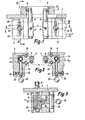
- the measurement object 2 rests on a carrier 1 (FIG. 1), in this case a ring 2 provided with an internal thread 2a.
- Two probe pins 7 and 8 engage with their measuring inserts 9 in a known manner in the thread 2a to be measured. They are adjustable in height in slides 5 and 6 and are held in place by means of screws 11.
- the carriages 5 and 6 are guided in the measuring jaws 3 and 4 so that they can move vertically to the measuring direction via ball guides 10.
- bolts 12 provided with handles 13 (FIGS. 2 and 3), which are equipped with leaf springs 14.
- the ends of these springs 14 engage in recesses 5a and 6a of the carriages 5 and 6. Stops 20 embedded in the bolt 12 (FIG. 3) limit the stroke of the springs and thereby protect them from overloading.
- the measuring jaw 3 is firmly connected to the carrier 1, during the Measuring jaws 4 is movably mounted in the measuring direction.
- the measuring jaw 4 is coupled to a measuring device, not shown, which indicates the extent of its displacement.
- the measurement itself takes place in that after the measurement jaw 4 has been withdrawn (to the left in FIG. 1), the measurement object 2 is placed on the carrier 1.
- the feeler pins 7 and 8 can now be roughly adjusted in height after loosening and tightening the screws 11 again.
- a finer adjustment is now carried out by means of the two handles 13, which allow the slide 5 and 6 as much free space as the springs 14 allow. If the measuring jaws 4 are moved into the measuring position and a measuring force F is applied to them, the slides 5 and 6 and with them the measuring inserts 9 can play freely into the threads of the thread 2a within the scope of the springs 14. This provides the ideal conditions for a correct measurement of the thread diameter.
- the example shown shows the measurement of internal threads.
- external threads can of course also be measured in an appropriate manner. It is also possible to measure diameters of all kinds, such as, for example, punctures.
Landscapes
- Physics & Mathematics (AREA)
- General Physics & Mathematics (AREA)
- A Measuring Device Byusing Mechanical Method (AREA)
- Length Measuring Devices With Unspecified Measuring Means (AREA)
- Length Measuring Devices By Optical Means (AREA)
Applications Claiming Priority (2)
| Application Number | Priority Date | Filing Date | Title |
|---|---|---|---|
| DE3200695 | 1982-01-08 | ||
| DE19823200695 DE3200695A1 (de) | 1982-01-08 | 1982-01-08 | Einrichtung zum messen von abstaenden insbesondere von gewinde-durchmessern |
Publications (3)
| Publication Number | Publication Date |
|---|---|
| EP0083817A2 true EP0083817A2 (fr) | 1983-07-20 |
| EP0083817A3 EP0083817A3 (en) | 1985-10-30 |
| EP0083817B1 EP0083817B1 (fr) | 1988-02-03 |
Family
ID=6152912
Family Applications (1)
| Application Number | Title | Priority Date | Filing Date |
|---|---|---|---|
| EP82201647A Expired EP0083817B1 (fr) | 1982-01-08 | 1982-12-21 | Dispositif pour la mesure de distances, en particulier pour les diamètres intérieurs de vis |
Country Status (4)
| Country | Link |
|---|---|
| US (1) | US4453316A (fr) |
| EP (1) | EP0083817B1 (fr) |
| JP (1) | JPS58122402A (fr) |
| DE (2) | DE3200695A1 (fr) |
Cited By (1)
| Publication number | Priority date | Publication date | Assignee | Title |
|---|---|---|---|---|
| CN104251653A (zh) * | 2014-09-26 | 2014-12-31 | 中色科技股份有限公司 | 一种用于测量碎边机啮合式刀盘径向尺寸的装置 |
Families Citing this family (11)
| Publication number | Priority date | Publication date | Assignee | Title |
|---|---|---|---|---|
| US4547970A (en) * | 1984-08-03 | 1985-10-22 | Brewster Albert L | Thread anvils for inside micrometer |
| DE3844825C2 (de) * | 1988-12-13 | 1996-06-05 | Rheinmetall Ind Gmbh | Meßeinrichtung zum Überprüfen von Gewindetoleranzen von Treibkäfigen |
| US5428355A (en) * | 1992-03-23 | 1995-06-27 | Hewlett-Packard Corporation | Position encoder system |
| US5414420A (en) * | 1992-03-23 | 1995-05-09 | Hewlett-Packard Corporation | Switch interconnect for position encoder system |
| US5416479A (en) * | 1992-03-23 | 1995-05-16 | Hewlett-Packard Corporation | Handle for position encoder system |
| DE4410195C1 (de) * | 1994-03-24 | 1995-11-09 | Zeiss Carl Jena Gmbh | Verfahren und Anordnung zum Messen kegliger Gewinde |
| CN102235857B (zh) * | 2010-11-29 | 2013-05-15 | 合肥市百胜科技发展股份有限公司 | 测径仪出口导卫 |
| CN103846616A (zh) * | 2012-11-30 | 2014-06-11 | 重庆长安工业(集团)有限责任公司 | 炮尾量规及其加工方法 |
| CN104613913B (zh) * | 2014-12-30 | 2017-04-12 | 浙江科技学院 | 一种斜滚道星形套自动测量机 |
| CN113701600B (zh) * | 2021-10-27 | 2022-01-18 | 如皋市宏茂铸钢有限公司 | 一种铸钢件圆内径快速测量设备 |
| JP2024152529A (ja) * | 2023-04-14 | 2024-10-25 | 株式会社ミツトヨ | 自動測定システムおよび自動測定システムの制御方法 |
Family Cites Families (16)
| Publication number | Priority date | Publication date | Assignee | Title |
|---|---|---|---|---|
| DE269567C (fr) * | ||||
| DE14869C (de) * | BOURCART SÖHNE & CO. in Gebweiler i./Elsafs | Traversirendcr Topf für Bänder und Vorgespinnstfäden für Spinnerei-Maschinen | ||
| FR484006A (fr) * | 1916-12-28 | 1917-08-28 | Cie Applic Mecaniques | Appareil de comparaison, par mesure directe, et de vérification des différents diamètres d'une circonférence |
| DE745881C (de) * | 1939-04-26 | 1944-05-30 | Carl Lombardino | Vorrichtung zur bezugsfreien Messung des Flankendurchmessers von Innengewinden |
| US2372879A (en) * | 1941-03-12 | 1945-04-03 | Skf Ind Inc | Gauging device |
| CH242187A (de) * | 1943-08-12 | 1946-04-30 | Skf Svenska Kullagerfab Ab | Apparat zum Messen von nutenförmigen Aussparungen in zylindrischen Flächen, insbesondere von Gewinden. |
| FR1106746A (fr) * | 1954-06-01 | 1955-12-22 | Calibre réglable par cales étalons récupérables pour arbres, alésages et filetages | |
| CH339743A (de) * | 1954-07-28 | 1959-07-15 | Standard Gage Co Inc | Messlehre |
| US3257729A (en) * | 1963-06-14 | 1966-06-28 | Richard W Fricke | Universal gauge device |
| US3346964A (en) * | 1966-03-03 | 1967-10-17 | Speedring Corp | Gaging device |
| GB1130016A (en) * | 1966-05-26 | 1968-10-09 | William Alfred Tuplin | Apparatus for setting a gauging device |
| US3432935A (en) * | 1966-07-25 | 1969-03-18 | Percy J Reish | Internal thread gauge |
| US3369302A (en) * | 1966-08-05 | 1968-02-20 | Johnson Co Gage | Internal dimensional gage with axially limited operating means |
| JPS5012364A (fr) * | 1973-06-08 | 1975-02-07 | ||
| JPS557161B2 (fr) * | 1973-12-28 | 1980-02-22 | ||
| US4184265A (en) * | 1978-01-12 | 1980-01-22 | Hydril Company | Thread gage |
-
1982
- 1982-01-08 DE DE19823200695 patent/DE3200695A1/de not_active Ceased
- 1982-12-21 DE DE8282201647T patent/DE3278086D1/de not_active Expired
- 1982-12-21 EP EP82201647A patent/EP0083817B1/fr not_active Expired
- 1982-12-28 US US06/454,001 patent/US4453316A/en not_active Expired - Lifetime
-
1983
- 1983-01-06 JP JP58000747A patent/JPS58122402A/ja active Pending
Cited By (1)
| Publication number | Priority date | Publication date | Assignee | Title |
|---|---|---|---|---|
| CN104251653A (zh) * | 2014-09-26 | 2014-12-31 | 中色科技股份有限公司 | 一种用于测量碎边机啮合式刀盘径向尺寸的装置 |
Also Published As
| Publication number | Publication date |
|---|---|
| DE3278086D1 (en) | 1988-03-10 |
| EP0083817A3 (en) | 1985-10-30 |
| US4453316A (en) | 1984-06-12 |
| EP0083817B1 (fr) | 1988-02-03 |
| DE3200695A1 (de) | 1983-07-21 |
| JPS58122402A (ja) | 1983-07-21 |
Similar Documents
| Publication | Publication Date | Title |
|---|---|---|
| EP0083817B1 (fr) | Dispositif pour la mesure de distances, en particulier pour les diamètres intérieurs de vis | |
| DE202012011761U1 (de) | Vorrichtung zur Überprüfung eines Kettenrades | |
| CH242187A (de) | Apparat zum Messen von nutenförmigen Aussparungen in zylindrischen Flächen, insbesondere von Gewinden. | |
| DE3724137A1 (de) | Messgeraet mit digitalanzeige | |
| DE2837781C3 (de) | Dreipunkt-Tischmeßgerät zum Messen von Kreisformfehlern | |
| DE3331014C2 (de) | Längenmeßvorrichtung, insbesondere zur Messung von Parallelendmaßen | |
| DE2936133C2 (de) | Dreipunkt-Tischmeßgerät zum Messen von Kreisformfehlern | |
| DE321630C (de) | Gewindemessvorrichtung | |
| DE1228070B (de) | Geraet zum Messen von Bohrungs-Innendurchmessern | |
| DE1798419B1 (de) | Aufnahmekopf fuer Mess- und Anreisswerkzeuge | |
| DE488426C (de) | Lochabstandslehre | |
| DE971007C (de) | Vorrichtung zum Messen und Pruefen von Bohrungen, insbesondere von kreisfoermigen Innenaussparungen oder -kammern | |
| CH250403A (de) | Kaliber zur vergleichenden Messung von Längen. | |
| DE859678C (de) | Messgeraet, insbesondere zum Pruefen der Zahnluecken von Zahn- und Kegelraedern | |
| DE2252465A1 (de) | Induktiv arbeitender messfuehler | |
| DE606106C (de) | Vorrichtung zum Pruefen der Zahnflanken von Evolventenraedern | |
| DE3142048A1 (de) | "messvorrichtung zur bestimmung der laengenverformung von rundstahlketten" | |
| DE10227884A1 (de) | Vorrichtung zur Durchführung von Messungen an Werkstücken | |
| DE867619C (de) | Pruefgeraet fuer Waelzfraeser | |
| DE876482C (de) | Trigonometrisches Rechengeraet | |
| EP0417677A1 (fr) | Dispositif pour mesurer des distances sur une pièce à usiner avec un pied à coulisse permettant de mesurer numériquement ces distances | |
| AT201302B (de) | Meßgerät zum Messen konischer Innengewinde | |
| DE1180144B (de) | Geraet zum Pruefen von Keilnuten | |
| CH214425A (de) | Messgerät. | |
| CH518519A (de) | Schiebelehre mit Hilfsorganen |
Legal Events
| Date | Code | Title | Description |
|---|---|---|---|
| PUAI | Public reference made under article 153(3) epc to a published international application that has entered the european phase |
Free format text: ORIGINAL CODE: 0009012 |
|
| AK | Designated contracting states |
Designated state(s): CH DE FR GB IT LI SE |
|
| PUAL | Search report despatched |
Free format text: ORIGINAL CODE: 0009013 |
|
| AK | Designated contracting states |
Designated state(s): CH DE FR GB IT LI SE |
|
| 17P | Request for examination filed |
Effective date: 19851122 |
|
| 17Q | First examination report despatched |
Effective date: 19870305 |
|
| GRAA | (expected) grant |
Free format text: ORIGINAL CODE: 0009210 |
|
| AK | Designated contracting states |
Kind code of ref document: B1 Designated state(s): CH DE FR GB IT LI SE |
|
| ITF | It: translation for a ep patent filed | ||
| GBT | Gb: translation of ep patent filed (gb section 77(6)(a)/1977) | ||
| REF | Corresponds to: |
Ref document number: 3278086 Country of ref document: DE Date of ref document: 19880310 |
|
| ET | Fr: translation filed | ||
| PLBE | No opposition filed within time limit |
Free format text: ORIGINAL CODE: 0009261 |
|
| STAA | Information on the status of an ep patent application or granted ep patent |
Free format text: STATUS: NO OPPOSITION FILED WITHIN TIME LIMIT |
|
| 26N | No opposition filed | ||
| PGFP | Annual fee paid to national office [announced via postgrant information from national office to epo] |
Ref country code: SE Payment date: 19911216 Year of fee payment: 10 |
|
| PGFP | Annual fee paid to national office [announced via postgrant information from national office to epo] |
Ref country code: GB Payment date: 19911217 Year of fee payment: 10 |
|
| PGFP | Annual fee paid to national office [announced via postgrant information from national office to epo] |
Ref country code: FR Payment date: 19911218 Year of fee payment: 10 |
|
| ITTA | It: last paid annual fee | ||
| PGFP | Annual fee paid to national office [announced via postgrant information from national office to epo] |
Ref country code: DE Payment date: 19920211 Year of fee payment: 10 |
|
| PGFP | Annual fee paid to national office [announced via postgrant information from national office to epo] |
Ref country code: CH Payment date: 19920326 Year of fee payment: 10 |
|
| PG25 | Lapsed in a contracting state [announced via postgrant information from national office to epo] |
Ref country code: GB Effective date: 19921221 |
|
| PG25 | Lapsed in a contracting state [announced via postgrant information from national office to epo] |
Ref country code: SE Effective date: 19921222 |
|
| PG25 | Lapsed in a contracting state [announced via postgrant information from national office to epo] |
Ref country code: LI Effective date: 19921231 Ref country code: CH Effective date: 19921231 |
|
| GBPC | Gb: european patent ceased through non-payment of renewal fee |
Effective date: 19921221 |
|
| PG25 | Lapsed in a contracting state [announced via postgrant information from national office to epo] |
Ref country code: FR Effective date: 19930831 |
|
| REG | Reference to a national code |
Ref country code: CH Ref legal event code: PL |
|
| PG25 | Lapsed in a contracting state [announced via postgrant information from national office to epo] |
Ref country code: DE Effective date: 19930901 |
|
| REG | Reference to a national code |
Ref country code: FR Ref legal event code: ST |
|
| EUG | Se: european patent has lapsed |
Ref document number: 82201647.3 Effective date: 19930709 |
|
| PGFP | Annual fee paid to national office [announced via postgrant information from national office to epo] |
Ref country code: LU Payment date: 19950501 Year of fee payment: 14 |