EP0083874A2 - Lampe fluorescente à type de faisceau - Google Patents
Lampe fluorescente à type de faisceau Download PDFInfo
- Publication number
- EP0083874A2 EP0083874A2 EP82307013A EP82307013A EP0083874A2 EP 0083874 A2 EP0083874 A2 EP 0083874A2 EP 82307013 A EP82307013 A EP 82307013A EP 82307013 A EP82307013 A EP 82307013A EP 0083874 A2 EP0083874 A2 EP 0083874A2
- Authority
- EP
- European Patent Office
- Prior art keywords
- electrodes
- fluorescent lamp
- beam mode
- cathode
- lamp
- Prior art date
- Legal status (The legal status is an assumption and is not a legal conclusion. Google has not performed a legal analysis and makes no representation as to the accuracy of the status listed.)
- Granted
Links
- 239000000463 material Substances 0.000 claims abstract description 19
- 230000005855 radiation Effects 0.000 claims abstract description 13
- 230000005284 excitation Effects 0.000 claims abstract description 7
- OAICVXFJPJFONN-UHFFFAOYSA-N Phosphorus Chemical compound [P] OAICVXFJPJFONN-UHFFFAOYSA-N 0.000 claims abstract description 4
- 239000011248 coating agent Substances 0.000 claims abstract description 4
- 238000000576 coating method Methods 0.000 claims abstract description 4
- QSHDDOUJBYECFT-UHFFFAOYSA-N mercury Chemical compound [Hg] QSHDDOUJBYECFT-UHFFFAOYSA-N 0.000 claims abstract description 4
- 229910052753 mercury Inorganic materials 0.000 claims abstract description 4
- 238000010894 electron beam technology Methods 0.000 claims description 22
- 230000009977 dual effect Effects 0.000 claims description 14
- 238000010438 heat treatment Methods 0.000 claims description 6
- 229910052756 noble gas Inorganic materials 0.000 claims description 6
- 238000010521 absorption reaction Methods 0.000 claims description 3
- 239000003990 capacitor Substances 0.000 claims description 2
- 229910052754 neon Inorganic materials 0.000 claims description 2
- GKAOGPIIYCISHV-UHFFFAOYSA-N neon atom Chemical compound [Ne] GKAOGPIIYCISHV-UHFFFAOYSA-N 0.000 claims description 2
- 230000002411 adverse Effects 0.000 abstract 1
- 239000004020 conductor Substances 0.000 description 14
- 238000004519 manufacturing process Methods 0.000 description 2
- 230000001133 acceleration Effects 0.000 description 1
- 238000010586 diagram Methods 0.000 description 1
- 230000003292 diminished effect Effects 0.000 description 1
- 239000011521 glass Substances 0.000 description 1
- 239000000203 mixture Substances 0.000 description 1
- 230000004048 modification Effects 0.000 description 1
- 238000012986 modification Methods 0.000 description 1
- 150000002835 noble gases Chemical class 0.000 description 1
- 239000000126 substance Substances 0.000 description 1
- 230000001502 supplementing effect Effects 0.000 description 1
Images
Classifications
-
- H—ELECTRICITY
- H01—ELECTRIC ELEMENTS
- H01J—ELECTRIC DISCHARGE TUBES OR DISCHARGE LAMPS
- H01J61/00—Gas-discharge or vapour-discharge lamps
- H01J61/70—Lamps with low-pressure unconstricted discharge having a cold pressure < 400 Torr
- H01J61/72—Lamps with low-pressure unconstricted discharge having a cold pressure < 400 Torr having a main light-emitting filling of easily vaporisable metal vapour, e.g. mercury
-
- H—ELECTRICITY
- H01—ELECTRIC ELEMENTS
- H01J—ELECTRIC DISCHARGE TUBES OR DISCHARGE LAMPS
- H01J63/00—Cathode-ray or electron-stream lamps
Definitions
- the present invention pertains to beam mode discharge fluorescent lamps and more particularly to an arrangement for configuring the electrodes within a beam mode discharge fluorescent lamp.
- the subject beam mode fluorescent lamp includes a light transmitting envelope enclosing a fill material, which emits ultraviolet radiation upon excitation.
- a phosphor coating on an inner surface of the envelope emits visible light upon absorption of ultraviolet radiation.
- each electrode has first and second ends. Each electrode is connected between an associated pair of conductors. The electrodes extend lengthwise and parallel to one another in the same horizontal plane, although any orientation of the plane would be functional. One conductor of each electrode is connected to an AC power source. The other conductor of each electrode is connected to a start circuit. These conductors also serve to support the electrodes at a stationary location within the envelope.
- Each electrode functions as both an anode and cathode under the two alternating polarities of an applied AC voltage.
- the electrode with the positive polarity voltage functions as an anode to accelerate an electron beam which was formed by the electrode with the negative polarity functioning as a cathode to emit electrons forming the electron beam.
- the accelerated electron beam then enters a drift region.
- the electrode which functioned as an anode now functions as the cathode to emit a second electron beam in the opposite direction to that of the first electron beam.
- the other electrode which previously operated as a thermionic cathode now operates as an anode to accelerate electrons of the second electron beam into a second drift region.
- the electrode which is functioning as the anode collects electrons. This current would usually be dissipated as simple heat. However, since the anode of the present half cycle is the cathode for the next half cycle, this current serves to heat the cathode for a more effective emission of electrons. This heat is usually wasted, but here it is used for keeping the cathodes heated suitably for electron emission.
- the first and second electron beams alternately drift through two drift regions within the envelope after passing their respective anodes on alternate half cycles of the AC voltage. Electrons in each electron beam collide with atoms of the fill material in the corresponding drift region, thereby causing excitation of a portion of the fill material atoms and emission of ultraviolet radiation and causing ionization of respective portions of the fill material atoms thereby yielding secondary electrons. These secondary electrons cause further emissions of ultraviolet radiation.
- the fill material typically includes mercury and a noble gas.
- Each electrode is spaced apart from the other electrode by a distance which is comparable to or somewhat less than the electron range in the fill material, approximately one centimeter.
- the structure of each electrode when functioning as an anode permits acceleration of an electron beam, with the amount of electrons collected by to the anode minimized.
- the lamp includes a base which encloses the start circuit and power source. Both conventional pre-heat and rapid start circuits may be employed as the start circuit of the present invention.
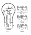
- Figure 1 is a perspective view of a schematic diagram of a dual cathode beam mode fluorescent lamp embodying the present invention.
- FIG. 2 illustrates various start circuits which may be employed in realizing the dual cathode beam mode fluorescent lamp of the present invention.
- a vacuum type lamp envelope 31 made of a light transmitting substance, such as glass, encloses a discharge volume.
- the discharge volume contains a fill material which emits ultraviolet radiation upon excitation.
- a typical fill material includes mercury and a noble gas or mixtures of noble gases.
- a suitable noble gas is neon.
- the inner surface of the lamp envelope 31 has a phosphor coating 37 which emits visible light upon absorption of ultraviolet radiation.
- Electrode 33 is connected between conductors 35 and 36 and electrode 34 is connected between conductors 28 and 29.
- Each of the conductors is of the same particular height so that the two electrodes 33 and 34 lie in the same horizontal plane.
- the electrodes 33 and 34 are oriented lengthwise parallel and spaced approximately one centimeter apart.
- Electrodes 33 and 34 are typically of a 20 volt thermionic type.
- the lamp further includes a base 38 which is of a conventional type, suitable for inserting into an incandescent lamp socket.
- Electrode 33 After the start circuit is activated by switching the lamp on, an AC voltage is applied to electrodes 33 and 34. On the first half cycle of the AC voltage, electrode 33 will be at a positive polarity with respect to electrode 34. As a result, electrode 34 will function as a thermionic cathode to emit electrons, thereby forming an electron beam as shown. Electrode 33 will function as an anode and operate to accelerate the electron beam into a corresponding first drift region 30.
- electrode 34 On the alternate half cycle of the AC voltage, electrode 34 will be positive with respect to electrode 33. Then, electrode 33 will function as a thermionic cathode to emit electrons forming a second electron beam, as a result. Electrode 34 will operate as an anode and accelerate the formed electron beam into a corresponding second drift region 30.
- the two drift regions 30 are located within the envelope 31 and extend in the direction of electron beam flow indicated, after passing their respective anodes on alternate half cycles of the AC voltage. Electrons in each region collide with atoms of the fill material, thereby causing excitation of a portion of the fill material atoms and emission of ultraviolet radiation and causing ionization of respective portions of the fill material atoms thereby yielding secondary electrons. These secondary electrons cause further emissions of ultraviolet radiation.
- the cathode heating current and the discharge current between electrodes 33 and 34 are both derived from the sane power source of enclosure 40. Only a single power source is required for the two functions.
- Power source 40 comprises a step-down transformer, which lowers the applied voltage to approximately 20 volts.
- the electrons which are collected by the particular electrode which is presently functioning as an anode will serve to heat this anode.
- the anode of the present half cycle is the cathode of the next half cycle. This heat stimulates the emission of electrons of the next half cycle by keeping a constant heat level and supplementing the ohmic heating provided by the power source.
- the lamp disclosed herein provides substantially more efficiency than a similar 100 watt incandescent lamp.
- the 100 watt incandescent lamp provides approximately 17 lumens/watt and a single electrode incandescent replacement (such as U.S. Patent application serial No. 219,564) provides about 25 lumens/watt.
- a single electrode incandescent replacement such as U.S. Patent application serial No. 219,564
- the present dual cathode beam mode fluorescent lamp was found to yield about 35 lumens/watt, an improvement of about 40%.
- FIG. 2A shows a pre-heat start circuit connected between conductors 35 and 29.
- This pre-heat start circuit is a series connection of a switch SW1 and resistor Rl.
- Figure 2B depicts a rapid start circuit composed of a resistor Rl and switch SW1, each connected in shunt to conductors 35 and 29.
- Figure 2C shows another rapid start circuit comprising a shunt connection of a capacitor Cl and switch SW1 across conductors 35 and 29.
- the pre-heat and rapid start circuits shown above are all of a conventional nature.
Landscapes
- Discharge Lamps And Accessories Thereof (AREA)
- Circuit Arrangements For Discharge Lamps (AREA)
- Discharge Lamp (AREA)
Applications Claiming Priority (2)
| Application Number | Priority Date | Filing Date | Title |
|---|---|---|---|
| US06/337,046 US4408141A (en) | 1982-01-04 | 1982-01-04 | Dual cathode beam mode fluorescent lamp |
| US337046 | 1982-01-04 |
Publications (3)
| Publication Number | Publication Date |
|---|---|
| EP0083874A2 true EP0083874A2 (fr) | 1983-07-20 |
| EP0083874A3 EP0083874A3 (en) | 1984-05-02 |
| EP0083874B1 EP0083874B1 (fr) | 1986-11-20 |
Family
ID=23318881
Family Applications (1)
| Application Number | Title | Priority Date | Filing Date |
|---|---|---|---|
| EP82307013A Expired EP0083874B1 (fr) | 1982-01-04 | 1982-12-31 | Lampe fluorescente à type de faisceau |
Country Status (5)
| Country | Link |
|---|---|
| US (1) | US4408141A (fr) |
| EP (1) | EP0083874B1 (fr) |
| JP (1) | JPS58145055A (fr) |
| CA (1) | CA1190588A (fr) |
| DE (1) | DE3274402D1 (fr) |
Cited By (2)
| Publication number | Priority date | Publication date | Assignee | Title |
|---|---|---|---|---|
| EP0115444A3 (en) * | 1983-02-01 | 1985-06-26 | Gte Laboratories Incorporated | Beam mode lamp with voltage modifying electrode |
| FR2575598A1 (fr) * | 1984-12-28 | 1986-07-04 | Dumas Pierre | Ampoule fluorescente a un culot a contact a emission transversale sur pied |
Families Citing this family (16)
| Publication number | Priority date | Publication date | Assignee | Title |
|---|---|---|---|---|
| US4751435A (en) * | 1984-12-13 | 1988-06-14 | Gte Laboratories Incorporated | Dual cathode beam mode fluorescent lamp with capacitive ballast |
| US4754194A (en) * | 1986-09-26 | 1988-06-28 | Wilson Feliciano | Flourescent light bulb |
| JPS63141252A (ja) * | 1986-12-02 | 1988-06-13 | Hitachi Ltd | 低圧放電灯 |
| JPS63264859A (ja) * | 1986-12-05 | 1988-11-01 | Matsushita Electric Works Ltd | 光放射電子管 |
| US4866339A (en) * | 1987-12-21 | 1989-09-12 | Gte Laboratories Incorporated | Beam mode fluorescent lamp |
| US5017831A (en) * | 1987-12-30 | 1991-05-21 | Gte Products Corporation | Glow discharge lamp with getter material on anode |
| US4904900A (en) * | 1987-12-30 | 1990-02-27 | Gte Products Corporation | Glow discharge lamp |
| US4929868A (en) * | 1989-01-05 | 1990-05-29 | Gte Products Corporation | Glow discharge lamp containing nitrogen |
| US5059864A (en) * | 1989-12-22 | 1991-10-22 | Gte Products Corporation | Negative glow lamp |
| US5006762A (en) * | 1990-04-09 | 1991-04-09 | Gte Products Corporation | Negative glow fluorescent lamp having discharge barrier |
| US5049785A (en) * | 1990-04-09 | 1991-09-17 | Gte Products Corporation | Two contact, AC-operated negative glow fluorescent lamp |
| US5146135A (en) * | 1990-10-17 | 1992-09-08 | Gte Products Corporation | Glow discharge lamp having anode probes |
| US5218269A (en) * | 1991-11-29 | 1993-06-08 | Gte Products Corporation | Negative glow discharge lamp having wire anode |
| US7029296B1 (en) * | 2000-02-07 | 2006-04-18 | Communication And Power Industires | Cover assembly for vacuum electron device |
| DE10016982A1 (de) * | 2000-04-06 | 2001-10-25 | Wedeco Ag | Verfahren zur Speisung eines UV-Licht-Niederdruckstrahlers und Vorschaltgerät zur Speisung eines UV-Licht-Niederdruck-Strahlers |
| MX2011005877A (es) | 2008-12-04 | 2011-09-06 | Univ California | Método y dispositivo de electroluminiscencia de ánodo de material semiconductor nanoestructurado con inyeccion de electrones. |
Family Cites Families (7)
| Publication number | Priority date | Publication date | Assignee | Title |
|---|---|---|---|---|
| US2283352A (en) * | 1930-10-15 | 1942-05-19 | Sirian Wire And Contact Compan | Lighting device |
| GB387130A (en) * | 1931-02-11 | 1933-02-02 | Carl Hummel | Improvements in or relating to electric discharge tubes for generating ultra-violet rays |
| US2409771A (en) * | 1943-07-08 | 1946-10-22 | Sylvania Electric Prod | Electrical discharge device |
| US2441863A (en) * | 1945-03-10 | 1948-05-18 | Gen Electric | Electrode for discharge devices |
| NL96689C (fr) * | 1956-06-27 | |||
| US2946909A (en) * | 1959-03-30 | 1960-07-26 | Westinghouse Electric Corp | Discharge device |
| EP0054959A1 (fr) * | 1980-12-23 | 1982-06-30 | GTE Laboratories Incorporated | Lampe fluorescente à rayons |
-
1982
- 1982-01-04 US US06/337,046 patent/US4408141A/en not_active Expired - Fee Related
- 1982-12-10 CA CA000417466A patent/CA1190588A/fr not_active Expired
- 1982-12-31 DE DE8282307013T patent/DE3274402D1/de not_active Expired
- 1982-12-31 EP EP82307013A patent/EP0083874B1/fr not_active Expired
-
1983
- 1983-01-04 JP JP58000026A patent/JPS58145055A/ja active Granted
Cited By (2)
| Publication number | Priority date | Publication date | Assignee | Title |
|---|---|---|---|---|
| EP0115444A3 (en) * | 1983-02-01 | 1985-06-26 | Gte Laboratories Incorporated | Beam mode lamp with voltage modifying electrode |
| FR2575598A1 (fr) * | 1984-12-28 | 1986-07-04 | Dumas Pierre | Ampoule fluorescente a un culot a contact a emission transversale sur pied |
Also Published As
| Publication number | Publication date |
|---|---|
| JPS58145055A (ja) | 1983-08-29 |
| EP0083874B1 (fr) | 1986-11-20 |
| DE3274402D1 (en) | 1987-01-08 |
| US4408141A (en) | 1983-10-04 |
| CA1190588A (fr) | 1985-07-16 |
| JPH0454341B2 (fr) | 1992-08-31 |
| EP0083874A3 (en) | 1984-05-02 |
Similar Documents
| Publication | Publication Date | Title |
|---|---|---|
| US4408141A (en) | Dual cathode beam mode fluorescent lamp | |
| EP1225613A4 (fr) | Dispositif emetteur d'electrons et source d'electrons le contenant, afficheur d'image a effet de champ, lampe fluorescente et leurs procedes de production | |
| CA1264063A (fr) | Lampe fluorescente a double cathode et ballast capacitif | |
| EP0115444B1 (fr) | Lampe à type de faisceau à électrode modifiant le voltage | |
| US4518897A (en) | Twin anode beam mode fluorescent lamp | |
| US4516057A (en) | Multi-electrode array for a beam mode fluorescent lamp | |
| EP0054959A1 (fr) | Lampe fluorescente à rayons | |
| US4494046A (en) | Single cathode beam mode fluorescent lamp for DC use | |
| US4450380A (en) | Multi-electrode array for a beam mode fluorescent lamp | |
| US4413204A (en) | Non-uniform resistance cathode beam mode fluorescent lamp | |
| US4996465A (en) | Variable color lighting device | |
| EP0084268A2 (fr) | Lampe fluorescente à type de faisceau à cathode simple pour usage à courant continu | |
| US3657591A (en) | High intensity far u.v. radiation source | |
| EP0377225A2 (fr) | Lampe à décharge luminescente contenant de l'azote | |
| US5059864A (en) | Negative glow lamp | |
| EP0087962A2 (fr) | Lampe fuorescente à type de faisceau à double cathode avec des extrémités unipotentielles | |
| US5146135A (en) | Glow discharge lamp having anode probes | |
| US2007924A (en) | Short wave length electric lamp | |
| JPS62157656A (ja) | 表示素子 | |
| JPH0572059B2 (fr) | ||
| JPH0582705B2 (fr) | ||
| RU2000132283A (ru) | Низковольтный катодолюминесцентный буквенно-цифровой и мозаичный экран | |
| JPH02242557A (ja) | 光放射電子管 | |
| JPH05166588A (ja) | 光放射電子管点灯回路 | |
| JPS62157655A (ja) | 表示素子 |
Legal Events
| Date | Code | Title | Description |
|---|---|---|---|
| PUAI | Public reference made under article 153(3) epc to a published international application that has entered the european phase |
Free format text: ORIGINAL CODE: 0009012 |
|
| 17P | Request for examination filed |
Effective date: 19830121 |
|
| AK | Designated contracting states |
Designated state(s): DE FR GB NL |
|
| PUAL | Search report despatched |
Free format text: ORIGINAL CODE: 0009013 |
|
| AK | Designated contracting states |
Designated state(s): DE FR GB NL |
|
| GRAA | (expected) grant |
Free format text: ORIGINAL CODE: 0009210 |
|
| AK | Designated contracting states |
Kind code of ref document: B1 Designated state(s): DE FR GB NL |
|
| REF | Corresponds to: |
Ref document number: 3274402 Country of ref document: DE Date of ref document: 19870108 |
|
| ET | Fr: translation filed | ||
| PLBE | No opposition filed within time limit |
Free format text: ORIGINAL CODE: 0009261 |
|
| STAA | Information on the status of an ep patent application or granted ep patent |
Free format text: STATUS: NO OPPOSITION FILED WITHIN TIME LIMIT |
|
| 26N | No opposition filed | ||
| PGFP | Annual fee paid to national office [announced via postgrant information from national office to epo] |
Ref country code: FR Payment date: 19900701 Year of fee payment: 9 |
|
| PGFP | Annual fee paid to national office [announced via postgrant information from national office to epo] |
Ref country code: GB Payment date: 19901219 Year of fee payment: 9 |
|
| PGFP | Annual fee paid to national office [announced via postgrant information from national office to epo] |
Ref country code: NL Payment date: 19901231 Year of fee payment: 9 |
|
| PGFP | Annual fee paid to national office [announced via postgrant information from national office to epo] |
Ref country code: DE Payment date: 19910130 Year of fee payment: 9 |
|
| PG25 | Lapsed in a contracting state [announced via postgrant information from national office to epo] |
Ref country code: GB Effective date: 19911231 |
|
| PG25 | Lapsed in a contracting state [announced via postgrant information from national office to epo] |
Ref country code: NL Effective date: 19920701 |
|
| NLV4 | Nl: lapsed or anulled due to non-payment of the annual fee | ||
| GBPC | Gb: european patent ceased through non-payment of renewal fee | ||
| PG25 | Lapsed in a contracting state [announced via postgrant information from national office to epo] |
Ref country code: FR Effective date: 19920831 |
|
| PG25 | Lapsed in a contracting state [announced via postgrant information from national office to epo] |
Ref country code: DE Effective date: 19920901 |
|
| REG | Reference to a national code |
Ref country code: FR Ref legal event code: ST |