EP0083985B1 - Dispositif pour l'emmagasinage d'une image obtenue par ultrasons - Google Patents
Dispositif pour l'emmagasinage d'une image obtenue par ultrasons Download PDFInfo
- Publication number
- EP0083985B1 EP0083985B1 EP83300111A EP83300111A EP0083985B1 EP 0083985 B1 EP0083985 B1 EP 0083985B1 EP 83300111 A EP83300111 A EP 83300111A EP 83300111 A EP83300111 A EP 83300111A EP 0083985 B1 EP0083985 B1 EP 0083985B1
- Authority
- EP
- European Patent Office
- Prior art keywords
- series
- samples
- digital
- digital signal
- elements
- Prior art date
- Legal status (The legal status is an assumption and is not a legal conclusion. Google has not performed a legal analysis and makes no representation as to the accuracy of the status listed.)
- Expired
Links
Images


Classifications
-
- G—PHYSICS
- G06—COMPUTING OR CALCULATING; COUNTING
- G06T—IMAGE DATA PROCESSING OR GENERATION, IN GENERAL
- G06T5/00—Image enhancement or restoration
- G06T5/90—Dynamic range modification of images or parts thereof
- G06T5/92—Dynamic range modification of images or parts thereof based on global image properties
-
- G—PHYSICS
- G01—MEASURING; TESTING
- G01S—RADIO DIRECTION-FINDING; RADIO NAVIGATION; DETERMINING DISTANCE OR VELOCITY BY USE OF RADIO WAVES; LOCATING OR PRESENCE-DETECTING BY USE OF THE REFLECTION OR RERADIATION OF RADIO WAVES; ANALOGOUS ARRANGEMENTS USING OTHER WAVES
- G01S7/00—Details of systems according to groups G01S13/00, G01S15/00, G01S17/00
- G01S7/52—Details of systems according to groups G01S13/00, G01S15/00, G01S17/00 of systems according to group G01S15/00
- G01S7/52017—Details of systems according to groups G01S13/00, G01S15/00, G01S17/00 of systems according to group G01S15/00 particularly adapted to short-range imaging
- G01S7/52023—Details of receivers
- G01S7/52025—Details of receivers for pulse systems
-
- G—PHYSICS
- G01—MEASURING; TESTING
- G01S—RADIO DIRECTION-FINDING; RADIO NAVIGATION; DETERMINING DISTANCE OR VELOCITY BY USE OF RADIO WAVES; LOCATING OR PRESENCE-DETECTING BY USE OF THE REFLECTION OR RERADIATION OF RADIO WAVES; ANALOGOUS ARRANGEMENTS USING OTHER WAVES
- G01S7/00—Details of systems according to groups G01S13/00, G01S15/00, G01S17/00
- G01S7/52—Details of systems according to groups G01S13/00, G01S15/00, G01S17/00 of systems according to group G01S15/00
- G01S7/52017—Details of systems according to groups G01S13/00, G01S15/00, G01S17/00 of systems according to group G01S15/00 particularly adapted to short-range imaging
- G01S7/52023—Details of receivers
- G01S7/52025—Details of receivers for pulse systems
- G01S7/52026—Extracting wanted echo signals
- G01S7/52028—Extracting wanted echo signals using digital techniques
-
- G—PHYSICS
- G01—MEASURING; TESTING
- G01S—RADIO DIRECTION-FINDING; RADIO NAVIGATION; DETERMINING DISTANCE OR VELOCITY BY USE OF RADIO WAVES; LOCATING OR PRESENCE-DETECTING BY USE OF THE REFLECTION OR RERADIATION OF RADIO WAVES; ANALOGOUS ARRANGEMENTS USING OTHER WAVES
- G01S7/00—Details of systems according to groups G01S13/00, G01S15/00, G01S17/00
- G01S7/52—Details of systems according to groups G01S13/00, G01S15/00, G01S17/00 of systems according to group G01S15/00
- G01S7/52017—Details of systems according to groups G01S13/00, G01S15/00, G01S17/00 of systems according to group G01S15/00 particularly adapted to short-range imaging
- G01S7/52053—Display arrangements
- G01S7/52057—Cathode ray tube displays
-
- G—PHYSICS
- G06—COMPUTING OR CALCULATING; COUNTING
- G06T—IMAGE DATA PROCESSING OR GENERATION, IN GENERAL
- G06T5/00—Image enhancement or restoration
- G06T5/40—Image enhancement or restoration using histogram techniques
Definitions
- the present invention relates, in general, to ultrasonic imaging, and, in particular, relates to an improved technique and device for storing and retrieving ultrasonic images of the type used in medical diagnostics.
- Ultrasonic imaging has found increased utility in the field of medical diagnosis. For example, ultrasonic imaging is utilized extensively for the detection and diagnosis of mammarian cancer. It is also utilized to ascertain various stages of fetal development. A major problem encountered with ultrasonic imaging has been the need to find a suitable technique for storing and retrieving the vast quantities of data generated when ultrasonic imaging techniques are employed.
- One technique employed for storing such data is to store information on photographic film.
- a typical mammarian scan for a single patient may comprise as many as sixty pages of photographs per patient with four photographs per page. Because of the unwieldy nature of such photographic records, less than a complete set of records may be collected and maintained for a given patient. Since record selection is generally done by a technician, the technician's judgment as to which data should be collected and which discarded may be substituted for that of the physician.
- ultrasonic imaging generates large quantities of digital data. While digital data storage techniques are available to store large quantites of digital data, retrieving such information may be sufficiently time consuming so as to be undesirable for a busy physician.
- One alternative is to provide a minimum digital storage capacity and to simply collect less data. In this manner, information retrieval time may be minimized but fewer than the optimum number of records per patient may be stored. Alternatively, if many records per patient are stored, but with data density for each record reduced, the image resolution record may be less than optimum.
- US-A-4 234 937 discloses a digital electronic system for improving the resolution of dynamic range-handling capacity for received ultrasound in reflection or transmission imaging systems.
- the disclosed ultrasonic tissue imaging system comprises an ultrasonic transducer, input imaging means for converting signals received by said transducer to an analog video input signal, means for producing a first series of digital amplitude samples representative of said video input signal, and display means responsive to a video output signal for producing an image of said tissue.
- the present invention takes advantage of the fact that an ultrasonic image is more highly variable in a direction along the axis of the ultrasonic transducer than in a direction transverse to that axis.
- the frequency of the axial component of a video signal representing an ultrasonic image is higher than the frequency of the transverse component.
- a storage and retrieval technique may be employed wherein the memory density allocated for storage of the transverse component is decreased without loss of axial resolution and without noticeable loss of transverse resolution.
- the second series of samples comprises fewer elements than the first series of samples, memory density may be decreased. However, since the second series of samples is the average of elements from the first series of samples, the second series of samples provides a reasonable approximation of the original video input signal. Since the frequency of the transverse component of the ultrasonic image is relatively low, such an approximation is sufficiently accurate faithfully to reproduce an ultrasonic image.
- compressing means for producing a third series of digital signals from the second digital signal series.
- the third digital signal series is a non-linear function of the second digital signal series, the non-linear function being such as to provide increased granularity in regions of greater interest from a diagnostic standpoint and decreased granularity in regions of lesser interest.
- a means for storing and retrieving the third digital signal series is provided and an expanding means is provided to reconstitute the second digital signal series from the retrieved third digital signal series.
- the reconstituted second digital signal series is thereafter smoothed and converted to analog form for video display. Since the stored digital signal employs increased granularity in regions of high interest, resolution in regions of interest is improved at the expense of slightly increased distortion in regions of low diagnostic interest.
- the ultrasonic imaging system of the present invention has the capability of storing 240 records or frames of information per patient.
- the ultrasonic imaging system 10 of the present invention employs an ultrasonic transducer 12 of conventional type. Signals received by the ultrasonic transducer 12 are directed to input imaging electronics 14.
- the input imaging electronics 14 are also of conventional design.
- the input imaging electronics 14 provides an analog video input signal which is representative of the ultrasonic image detected by the transducer 12. 176 lines of the analog video input signal constitute one frame or record of information from a given patient.
- the analog video input signal emanating from the input imaging electronics 14 is directed to an image storage and retrieval circuit 16 of the present invention, which will be described in detail in connection with Fig.
- the image storage and retrieval circuit 16 is effective to convert the analog video input signal to digital form and for directing the digital signal to a peripheral storage means 18.
- the peripheral storage means 18 preferably comprises a three megabyte floppy disk.
- image storage and retrieval means 16 retrieves patient records from the peripheral storage means 18 and converts such records to analog form.
- the converted analog signals are then directed to output imaging electronics 118, also of conventional design, which converts the signals to a form suitable for display on a cathode ray tube such as shown at 120.
- the image storage and retrieval means 16 of the present invention includes an analog-to-digital converter 22 which is responsive to the analog video input signal from the input imaging electronics 14.
- the analog to digital converter 22 samples the analog video input signal at a rate of, for example, 10 MHz to produce a first digital input signal comprising a first series of amplitude samples representative of the analog input signal.
- the first series of samples preferably comprises 512 samples of information per line. Each sample comprises a 6-bit value corresponding to an instantaneous amplitude of the analog input signal.
- the first series of amplitude samples is directed to a video input processing circuit 24 which will be described in detail in connection with Fig. 3 below.
- the output of the video input processing circuit 24 is a second digital signal which is directed through a switch 26 to an input memory 28.
- the switch 26 operates under the control of a microprocessor control means 30.
- the output of memory 28 is connected by means of a switch 32, also under the control of the control means 30, to a direct memory access means 34.
- the microprocessor controller 30 controls switches 26 and 32 so as to store the second digital signal emanating from the video input processing circuit 24 in the input memory 28.
- the direct memory access means 34 is activated by the microprocessor controller 30 so as to transfer the stored information from input memory 28 through the disk interface 36 to the peripheral storage means 18. Images are directed to the peripheral storage means 18 at a rate of, for example, four frames per second.
- the switches 26 and 32 are opened at the command of the microprocessor controller 30. Retrieved information from the peripheral storage means 18 is thereafter directed through the disk interface 36 and the direct memory access means 34 to either one or the other of output memories 38 and 40, the particular one being determined by the position of the switching means 42.
- the switching means 42 also operates under the control of the microprocessor controller 30. Two memory means 38 and 40 are provided so that retrieval from the storage means 18 to either output memory 38 or 40 can be overlapped in time with the viewing of a previously retrieved image in the alternate output memory 40 or 38. In this way, a continuous visual image is achieved.
- each of the output memories 38 and 40 contain a second digital signal retrieved from peripheral storage means 18.
- This retrieved, second digital signal is directed through a switching means 44, also under the control of microprocessor controller 30, to a video output processing circuit 46, which will be described in more detail in connection with Fig. 5 below.
- the video output processing circuit 46 reconstitutes the first digital signal from the second digital signal input thereto by performing an inverse transform of the type performed in the video input processing circuit 24.
- the first digital signal output from the video output processing circuit 46 is directed to digital-to-analog converter 48 which produces a video output signal substantially similar to the analog video input signal which was originally received from input imaging electronics 14.
- the video output signal is an analog signal which is directed to the video display 120 referred to in connection with Fig. 1 above.
- the image storage and retrieval means 16 of the present invention further includes a character generating means 100 which is under the control of the microprocessor controller 16.
- the digital-to-analog converter 48 is responsive to the character generating means 100 so that upon command of the microprocessor controller 30, alphanumeric information may be simultaneously or sequentially displayed along with patient records.
- the video input processing circuit 24 includes a means for reducing the data density of ultrasonic images in a direction lateral to the axis of the transducer 12.
- This means includes a first latch 50, a summing means 52, a second latch 54, and a first digital multiplexer 56.
- the video input processing circuit 24 also includes in accordance with a preferred aspect of the present invention, a compressing means 58, a third latch 60 and a fourth latch 62.
- the first six-bit sample of the first digital input signal from the analog-to-digital converter 22 is directed to the first latch 50 and from there to the summing means 52, as shown.
- the first six-bit sample of the first digital signal is added to the eight-bit output of the first digital multiplexer 56, which output is initially zero.
- the eight-bit output of the summing means 52 is directed to a second latch 54, the output of which is directed to an input of the first digital multiplexer 56.
- the second six-bit sample of the first digital input signal from the analog-to-digital converter 22 is then directed to the latch 50 and from there to the summing means 52, where it is added to the last preceding eight-bit sample of that digital signal from the digital multiplexer 56.
- the most significant six bits of the eight bits stored in latch 54 are directed to the compressing means 58. These six bits comprise the average of four successive samples of the first digital signal.
- the analog-to-digital converter 22 provides a first series of amplitude samples.
- a second series of digital amplitude samples is provided which is related to the first series.
- the second series of amplitude samples has fewer elements than the first series since each element b n , of the second series of amplitude samples is an average of a group of four elements, a m , a m +1, a m +2, and a m +3 of the first series of samples. Since the second series of samples has but one fourth the number of samples than the first series, and since the second series of samples (preferably after compressing as explained below) is ultimately stored in storage means 18, memory density is appreciably reduced.
- each element, b n of the second series of samples is comprised of the average of four elements, a m through a m +3 of the first series of samples
- the output of latch 54 could also comprise the average of some different number of samples from analog-to-digital converter 22 as opposed to the four samples referred to above.
- each element of the second series of samples is related to the elements of the first series of samples by the relationship where n is a positive integer identifying each element of the second series of samples and k is the number of elements in each group of elements being summed.
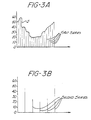
- Fig. 3A is a plot of the amplitude versus time of the output of the analog-to-digital converter 22.
- An analog video input signal S is sampled by the analog-to-digital converter 22 to form the first series of amplitude samples shown in Fig. 3A.
- a second series of amplitude samples is produced, each element of which is an average of a group of samples shown in Fig. 3A.
- the second series of amplitude samples shown in Fig. 3B is a reasonably accurate approximation of that video input signal. Since the number of elements in the second series (Fig. 3B) is less than the number of elements in the first series (Fig. 3A) the memory capacity requirements of the peripheral means 18 are substantially reduced.
- the compressing means 58 is a random access memory, the output of which is a third digital signal (four bit), the third digital signal being a non-linear function of the samples of the second digital signal input thereto. In this manner, the granularity of the second digital signal is increased in regions of greater diagnostic interest and decreased in regions of lesser interest.
- the transfer function of the compressing means 58 will be described in detail in connection with Fig. 4 below.
- the output of the compressing means 58 is a four-bit binary number and since the data format employed by most commonly utilized peripheral storage means is an eight-bit format, the output of the compressing means 58 may be converted to an eight-bit format by taking the first four-bit byte from the compressing means 58 and storing it in a latch 60. The next four-bit byte from the compressing means 58 is immediately directed to the fourth latch (eight bits) 62, wherein the four-bit byte stored in latch 60 is combined to form an eight-bit byte directed to the input memory 28.
- Fig. 4 the transfer function of the compressing means 58 will be described in detail.
- the transfer function compress output versus compress input
- the plot is a monotonically increasing curve with a monotonically decreasing slope.
- the granularity of low level input signals is increased at the expense of high amplitude level input signals.
- resolution is enhanced for low level signals at the expense of high level signals, low level signals corresponding to areas of possible malignancy.
- a change in the value of the input to the compressing means 58 produces a greater change in the value of the output of the compressing means at lower values of the compressing means input than at higher values of that input.
- the video output processing circuit includes a latch 64 to which retrieved eight-bit digital information from the peripheral storage means 18 is directed.
- the digital signal from the latch 64 is directed to a multiplexer 66 in which it is converted to two four-bit bytes.
- the digital signal from the multiplexer 66 is then directed to the expanding means 68 in accordance with a preferred aspect of the present invention.
- the expanding means is operative to convert the retrieved third digital signal from the storage means 18 to a reconstituted second digital signal.
- the reconstituted digital signal output from the expanding means 68 is a non-linear function of the digital signal input thereto.
- the transfer function of the expanding means 68 will be seen.
- the transfer function of the expanding means 58 (expand input versus expand output) is a monotonically increasing function with a monotonically increasing slope.
- the transfer function of the expanding means 68 is the inverse of the transfer function of the compressing means 58.
- the compressing means 58 preferably comprises a random access memory, each value of the third digital signal stored therein being located at an address determined by a value of the second digital signal input thereto.
- the expanding means 68 also comprises a random access memory storing the various values of the second digital signal at addresses determined by values of the retrieved third digital signal.
- the output of the expanding means 68 is directed to a smoothing circuit comprised of a latch 70 and a summing means 72, the output of the summing means then being directed to another latch 74.
- Each of the latches 70 and 74 are strobed by clock pulses (from a clock means not shown).
- the latch 74 is strobed at a rate twice that of the rate utilized to strobe latch 70.
- the output of latch 74 is a digital signal comprising a fourth series of digital samples, each element, Cn , of which is related to the elements, b n of the second series of digital samples by the relationships: where n is a positive even integer; and where n is a positive odd integer.
- the digital signal emanating from the latch 74 comprises a series of amplitude samples c " , c " +1..., etc., the fourth series being directed to the digital-to-analog converter 48 where an analog signal suitable for video display is produced.
Landscapes
- Engineering & Computer Science (AREA)
- Physics & Mathematics (AREA)
- General Physics & Mathematics (AREA)
- Computer Networks & Wireless Communication (AREA)
- Radar, Positioning & Navigation (AREA)
- Remote Sensing (AREA)
- Theoretical Computer Science (AREA)
- Ultra Sonic Daignosis Equipment (AREA)
Claims (5)

Applications Claiming Priority (4)
| Application Number | Priority Date | Filing Date | Title |
|---|---|---|---|
| US06/338,730 US4412248A (en) | 1982-01-11 | 1982-01-11 | Ultrasonic image storage device and method |
| US06/338,731 US4412249A (en) | 1982-01-11 | 1982-01-11 | Ultrasonic image storage device and method |
| US338731 | 1982-01-11 | ||
| US338730 | 1994-11-14 |
Related Child Applications (2)
| Application Number | Title | Priority Date | Filing Date |
|---|---|---|---|
| EP85201996.7 Division-Into | 1983-01-10 | ||
| EP85201996A Division EP0181677A3 (fr) | 1982-01-11 | 1983-01-10 | Dispositif et procédé pour l'emmagasinage d'une image obtenue par ultrasons |
Publications (2)
| Publication Number | Publication Date |
|---|---|
| EP0083985A1 EP0083985A1 (fr) | 1983-07-20 |
| EP0083985B1 true EP0083985B1 (fr) | 1988-04-06 |
Family
ID=26991337
Family Applications (2)
| Application Number | Title | Priority Date | Filing Date |
|---|---|---|---|
| EP83300111A Expired EP0083985B1 (fr) | 1982-01-11 | 1983-01-10 | Dispositif pour l'emmagasinage d'une image obtenue par ultrasons |
| EP85201996A Withdrawn EP0181677A3 (fr) | 1982-01-11 | 1983-01-10 | Dispositif et procédé pour l'emmagasinage d'une image obtenue par ultrasons |
Family Applications After (1)
| Application Number | Title | Priority Date | Filing Date |
|---|---|---|---|
| EP85201996A Withdrawn EP0181677A3 (fr) | 1982-01-11 | 1983-01-10 | Dispositif et procédé pour l'emmagasinage d'une image obtenue par ultrasons |
Country Status (4)
| Country | Link |
|---|---|
| EP (2) | EP0083985B1 (fr) |
| AU (1) | AU1026283A (fr) |
| CA (1) | CA1192654A (fr) |
| DE (1) | DE3376234D1 (fr) |
Families Citing this family (5)
| Publication number | Priority date | Publication date | Assignee | Title |
|---|---|---|---|---|
| FR2614450A1 (fr) * | 1987-04-21 | 1988-10-28 | Labo Electronique Physique | Procede et appareil d'examen de milieux par echographie ultrasonore |
| GB2268806B (en) * | 1992-07-14 | 1997-02-26 | Intravascular Res Ltd | Methods and apparatus for the examination and treatment of internal organs |
| GB2293240B (en) * | 1994-09-15 | 1998-05-20 | Intravascular Res Ltd | Ultrasonic visualisation method and apparatus |
| US6254542B1 (en) | 1995-07-17 | 2001-07-03 | Intravascular Research Limited | Ultrasonic visualization method and apparatus |
| CA2962785A1 (fr) * | 2014-10-07 | 2016-04-14 | Butterfly Network, Inc. | Circuiterie de traitement de signal a ultrasons, et appareil et procedes associes |
Family Cites Families (9)
| Publication number | Priority date | Publication date | Assignee | Title |
|---|---|---|---|---|
| US3979555A (en) * | 1975-05-27 | 1976-09-07 | Hughes Aircraft Company | Histogram equalization system for display improvement |
| US4234937A (en) * | 1976-08-03 | 1980-11-18 | Indianapolis Center For Advanced Research | Peak detector for resolution enhancement of ultrasonic visualization systems |
| AU517998B2 (en) * | 1977-05-06 | 1981-09-10 | Commonwealth Of Australia, The | Signal processing system |
| DE2806176C3 (de) * | 1978-02-14 | 1980-08-07 | Siemens Ag, 1000 Berlin Und 8000 Muenchen | Verfahren und Vorrichtung zur Gewinnung und Aufzeichnung von Ultraschall-Schnittbildern |
| US4247815A (en) * | 1979-05-22 | 1981-01-27 | The United States Of America As Represented By The Secretary Of The Army | Method and apparatus for physiologic facsimile imaging of biologic targets based on complex permittivity measurements using remote microwave interrogation |
| IL58119A (en) * | 1979-08-27 | 1983-03-31 | Yeda Res & Dev | Histogram image enhancement system |
| US4360840A (en) * | 1980-05-13 | 1982-11-23 | Am International, Inc. | Real time data compression/decompression scheme for facsimile transmission system |
| GB2069264A (en) * | 1980-07-02 | 1981-08-19 | Hewlett Packard Co | Data compression apparatus |
| US4363036A (en) * | 1981-03-16 | 1982-12-07 | Ncr Canada Ltd - Ncr Canada Ltee | Method and apparatus for compressing digital data using non-adaptive predictive techniques |
-
1983
- 1983-01-07 CA CA000419120A patent/CA1192654A/fr not_active Expired
- 1983-01-10 AU AU10262/83A patent/AU1026283A/en not_active Abandoned
- 1983-01-10 EP EP83300111A patent/EP0083985B1/fr not_active Expired
- 1983-01-10 EP EP85201996A patent/EP0181677A3/fr not_active Withdrawn
- 1983-01-10 DE DE8383300111T patent/DE3376234D1/de not_active Expired
Non-Patent Citations (2)
| Title |
|---|
| IEEE TRANSACTIONS ON SONICS AND ULTRASONICS, vol. SU-21, no. 2, April 1974, New York (USA); DIANA H. McSHERRY: "Computer Processing of Diagnostic Ultrasound Data", pages 91-97 * |
| WESCON67 TECNICAL PAPTERS, vol. 11, no. 3, Session 6, 22nd-25th August 1967, North Hollywood (US); G.M. LOH: "Mechanization of a Digital Compressor for Biomedical Data", paper 6/1, pages 1-12 * |
Also Published As
| Publication number | Publication date |
|---|---|
| AU1026283A (en) | 1983-07-21 |
| EP0181677A2 (fr) | 1986-05-21 |
| EP0083985A1 (fr) | 1983-07-20 |
| EP0181677A3 (fr) | 1986-07-23 |
| DE3376234D1 (en) | 1988-05-11 |
| CA1192654A (fr) | 1985-08-27 |
Similar Documents
| Publication | Publication Date | Title |
|---|---|---|
| US4271842A (en) | Apparatus and method for providing multiple ultrasonic sector image displays | |
| US5274759A (en) | Ultrasonic diagnostic apparatus capable of multi-frame representation | |
| US6231508B1 (en) | Ultrasonic diagnostic imaging system with digital video image marking | |
| US4680628A (en) | Realtime digital diagnostic image processing system | |
| US4730212A (en) | Realtime digital diagnostic image processing system | |
| EP1041396B1 (fr) | Appareil de diagnostic par ultrasons | |
| US6213944B1 (en) | Ultrasonic diagnostic imaging system with a digital video recorder with visual controls | |
| EP1118019A1 (fr) | Imagerie ultrasonique avec agrandissement par voies de traitements independantes | |
| JP2002538863A (ja) | ディジタルビデオレコーダを備えた超音波診断撮像システム | |
| US6215900B1 (en) | Image data processing for digital x-ray detectors | |
| US4412248A (en) | Ultrasonic image storage device and method | |
| EP0415324B1 (fr) | Appareil de diagnostic ultra-sonore | |
| US4428059A (en) | Real time fill circuit | |
| US4197583A (en) | Image display system | |
| US4412249A (en) | Ultrasonic image storage device and method | |
| EP0181677A2 (fr) | Dispositif et procédé pour l'emmagasinage d'une image obtenue par ultrasons | |
| US4275595A (en) | Process and installation for producing and recording ultrasonic sectional images | |
| JP2005508587A (ja) | 超音波ビデオ画像情報のリアルタイムでの記憶を実行する方法及び装置 | |
| EP0128764B1 (fr) | Procédé et dispositif pour la compression d'un signal d'image de rayonnement | |
| EP0050843B1 (fr) | Convertisseur de balayage numérique | |
| Dinn et al. | CINTEL—computer interface for television | |
| JPH11164831A (ja) | 超音波診断装置 | |
| JP2892676B2 (ja) | 画像データ圧縮方法 | |
| Ligtvoet et al. | Direct conversion of real-time two-dimensional echocardiographic images | |
| JPH0337936B2 (fr) |
Legal Events
| Date | Code | Title | Description |
|---|---|---|---|
| PUAI | Public reference made under article 153(3) epc to a published international application that has entered the european phase |
Free format text: ORIGINAL CODE: 0009012 |
|
| AK | Designated contracting states |
Designated state(s): DE FR GB |
|
| 17P | Request for examination filed |
Effective date: 19840111 |
|
| GRAA | (expected) grant |
Free format text: ORIGINAL CODE: 0009210 |
|
| AK | Designated contracting states |
Kind code of ref document: B1 Designated state(s): DE FR GB |
|
| PG25 | Lapsed in a contracting state [announced via postgrant information from national office to epo] |
Ref country code: FR Free format text: THE PATENT HAS BEEN ANNULLED BY A DECISION OF A NATIONAL AUTHORITY Effective date: 19880406 |
|
| REF | Corresponds to: |
Ref document number: 3376234 Country of ref document: DE Date of ref document: 19880511 |
|
| EN | Fr: translation not filed | ||
| PLBI | Opposition filed |
Free format text: ORIGINAL CODE: 0009260 |
|
| 26 | Opposition filed |
Opponent name: SIEMENS AKTIENGESELLSCHAFT, BERLIN UND MUENCHEN Effective date: 19890103 |
|
| PG25 | Lapsed in a contracting state [announced via postgrant information from national office to epo] |
Ref country code: DE Effective date: 19891003 |
|
| PGFP | Annual fee paid to national office [announced via postgrant information from national office to epo] |
Ref country code: GB Payment date: 19920103 Year of fee payment: 10 |
|
| PLBN | Opposition rejected |
Free format text: ORIGINAL CODE: 0009273 |
|
| STAA | Information on the status of an ep patent application or granted ep patent |
Free format text: STATUS: OPPOSITION REJECTED |
|
| 27O | Opposition rejected |
Effective date: 19920219 |
|
| PG25 | Lapsed in a contracting state [announced via postgrant information from national office to epo] |
Ref country code: GB Effective date: 19930110 |
|
| GBPC | Gb: european patent ceased through non-payment of renewal fee |
Effective date: 19930110 |