EP0083995A2 - Dispositif vertical et procédé pour séparer des gouttes - Google Patents
Dispositif vertical et procédé pour séparer des gouttes Download PDFInfo
- Publication number
- EP0083995A2 EP0083995A2 EP83300137A EP83300137A EP0083995A2 EP 0083995 A2 EP0083995 A2 EP 0083995A2 EP 83300137 A EP83300137 A EP 83300137A EP 83300137 A EP83300137 A EP 83300137A EP 0083995 A2 EP0083995 A2 EP 0083995A2
- Authority
- EP
- European Patent Office
- Prior art keywords
- gas
- liquid
- liquids
- compartment
- uppermost
- Prior art date
- Legal status (The legal status is an assumption and is not a legal conclusion. Google has not performed a legal analysis and makes no representation as to the accuracy of the status listed.)
- Ceased
Links
Images


Classifications
-
- E—FIXED CONSTRUCTIONS
- E21—EARTH OR ROCK DRILLING; MINING
- E21B—EARTH OR ROCK DRILLING; OBTAINING OIL, GAS, WATER, SOLUBLE OR MELTABLE MATERIALS OR A SLURRY OF MINERALS FROM WELLS
- E21B43/00—Methods or apparatus for obtaining oil, gas, water, soluble or meltable materials or a slurry of minerals from wells
- E21B43/34—Arrangements for separating materials produced by the well
-
- B—PERFORMING OPERATIONS; TRANSPORTING
- B01—PHYSICAL OR CHEMICAL PROCESSES OR APPARATUS IN GENERAL
- B01D—SEPARATION
- B01D53/00—Separation of gases or vapours; Recovering vapours of volatile solvents from gases; Chemical or biological purification of waste gases, e.g. engine exhaust gases, smoke, fumes, flue gases, aerosols
- B01D53/26—Drying gases or vapours
Definitions
- This invention relates to apparatus and methods for preventing freezing of liquids during separation of liquids from natural gas at the well head.
- Natural gas at the well head contains liquids such as water and hydrocarbons which are removed from the natural gas by a preliminary separator apparatus and/or a secondary dehydrator apparatus such as disclosed in Rodney T. Heath prior United States Patent No. 3,541,763.
- This invention is particularly directed to preliminary separator apparatus and provides the primary function of removing liquids from the natural gas while preventing freezing of the liquids.
- belowground apparatus has been used which has a manually operable vent system for discharging liquids collected below ground at predetermined intervals.
- aboveground apparatus has been used which provides for automatic venting of liquids collected above-ground which are kept from freezing by an associated heater device.
- prior art separator apparatus and vent controls therefor have been located either above or below ground level.
- An advantage of aboveground separator apparatus and controls is that the operator can visually inspect the apparatus to determine that the apparatus is functioning properly and accumulated liquids may be automatically removed from the apparatus.
- a disadvantage of above- ground equipment is that, on low volume, low pressure gas wells, the flow velocity may not be great enough to keep the flow line between the well and separator swept clean of liquids and well line freezes between the well and separator may result.
- An advantage of belowground apparatus is that the liquids from the well line are collected below the frost line and are not as susceptible to freezing.
- a disadvantage of belowground apparatus is that automation of liquid discharge is difficult, fluid levels cannot be easily determined, and the operator has difficulty in determining if the apparatus is properly functioning.
- the primary object of the present invention is to provide a freeze-proof preliminary separator system having an unheated first stage underground system associated with a heated second stage aboveground system.
- An additional object is to provide liquid discharge means for automatic transfer of liquids collected in the underground system to the aboveground system while preventing freezing of the liquids during transfer therebetween.
- Another object is to provide inspection means whereby operating or maintenance personnel can easily determine if the underground system is functioning properly.
- the separator system of present invention comprises an elongated cylindrical tank of relatively long length, e.g. approximately 4.5 meters (15 feet), and relatively small diameter, e.g. approximately 0.3 meter (1 foot), mounted in a vertical attitude with a lowermost portion of substantial length, e.g. 1.2 meters (4 feet), buried in the ground in the vicinity of a natural gas well head.
- the tank is divided into upper and lower compartments by a divider plate located a relatively short distance, e.g. approximately 0.3 meter (one foot) above ground level.
- the lower compartment has a tank inlet opening located above the bottom of the tank and beneath the divider plate so as to be connectable to an underground natural gas pipeline located beneath the frost line for a particular geographical location of a natural gas well which supplies natural gas to the separator system.
- the lower compartment is connected to the aboveground upper compartment by a fluid passage in a tubular member mounted in a vertical attitude in the tank in juxtaposition to a side wall portion of the tank opposite the tank inlet opening.
- a gas-liquid inlet opening is provided in the lower end portion of the tubular member adjacent the bottom of the tank and a gas-liquid outlet opening is provided in the upper end portion of the tubular member a substantial distance, e.g. approximately 0.6 meter (2 feet), above the divider plate in the upper compartment.
- Gas and liquids, such as water and hydrocarbons, from the well head flow into the lower compartment through the tank inlet opening and downwardly toward the bottom of the tank and the tubular gas-liquid inlet opening adjacent the bottom of the tank which provides a reservoir for the liquids.
- the relatively high pressure e.g., 100 to 150 psi
- the liquids collected in the second liquid reservoir are automatically periodically removed from the upper compartment by actuation of a conventional float operated control means whenever the level of liquids in the upper compartment rises above a predetermined maximum level.
- the gas in the second compartment flows upwardly through a conventional gas-liquid separator means, such as a wire mesh mist extractor device, to provide relatively dry supply gas in the upper end portion of the upper compartment which is connected to a gas discharge line through a gas outlet opening in the tank.
- a housing is mounted about an intermediate aboveground portion of the tank, which includes the second liquid reservoir, and a gas operated heat generating device is associated with the housing to heat and prevent freezing of the liquids and supply gas in the second reservoir and in the upper compartment. If operation of the separator system is terminated for any reason, the liquids in the first reservoir located below the ground frost line level in the lower compartment are protected against freezing.
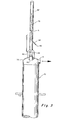
- the separator apparatus of the present invention comprises an elongated cylindrical tank means 10 which is adapted to be set in a vertical attitude in a hole in the ground adjacent a natural gas well head.
- a gas inlet opening means 12 is adapted to be connected to an underground well gas supply pipeline (not shown) located below the frost line.
- a gas outlet opening means 14, located above inlet opening means 12 at the top of the tank means 10, is adapted to be connected to a gas supply pipeline (not shown).
- a stabilizer means 16, in the form of four laterally extending plate members 18, 20, 22, 24, Fig. 4, is fixed to a lower portion of tank means 10.
- a housing means 26, Fig. 2 encloses an upper portion of tank means 10 and has an access door 28 mounted on hinge devices 30, 32 with a latch device 34 to hold the door closed.
- tank means 10 is divided into upper and lower elongated cylindrical compartments 40, 42 by a plate member 44.
- a relatively small diameter tubular member 46 is fixedly mounted in tank means 10 adjacent a portion of the tank wall opposite inlet opening means 12 to provide gas-liquid discharge means for transferring gas and liquids from the lower compartment to the upper compartment as hereinafter described.
- Lower end portion 48 of tubular member 46 is located relatively closely adjacent a domed bottom end cap member 50 of tank means 10 and provides a downwardly facing circular fluid inlet opening 52.
- Upper end portion 54 of tubular member 46 which extends through and is sealed relative to plate member 44, terminates in a beveled outlet opening 56 located beneath a baffle plate means 58 fixed to the side wall of the tank means.
- a vertically downwardly extending dip tube member 60 is connected at the upper end below plate member 44 to a manually operable needle valve 62 through the side wall of tank means 10 to provide above- ground inspection means for determining the level of liquids in the lower compartment.
- a vertically extending tubular member 64 is fixedly mounted along a portion of the side wall of tank means 10 in upper compartment 40 laterally opposite tubular member 46 to provide liquid discharge means for removing liquids from the upper compartment.
- the lower end portion of tubular member 64 has a downwardly inwardly facing beveled opening 66 adjacent plate member 44.
- the upper end portion of tubular member 64 has a laterally facing portion 68 connected to a dump valve 69, Fig. 2, through a coupling member 70 mounted in the side wall of tank means 10.
- a conventional mist extractor means 72 such as a wire mesh block of wires of different diameters woven into mesh form, is mounted across the upper end portion of upper compartment 40 below gas outlet opening 14, connected to a pipeline (not shown).
- the upper end of tank means 10 is closed by a domed end cap member 76.
- a vertically extending tube member 78, Fig. 3, is mounted on and extends through a coupling 80 on end cap member 76.
- a relatively small diameter tube 81 is mounted in tube member 78 with a gas inlet opening 82 at the upper end and a gas discharge opening 83 in the lower outwardly inclined end portion 84 which extends through the outer tube 78 for connection to a heater supply gas line (not shown).
- a support flange member 85 having an opening 86 for attachment of a hook or cable (not shown) is mounted on end cap member 76 to support tank means 10 during installation.
- well gas which may have a relatively low pressure, e.g. 690 to 1034 kPa (100 to 150 psi) or more, flows into lower compartment 42 through inlet opening 12 as indicated by arrow 90, Fig. 5.
- the gas then flows downwardly toward domed lower end cap member 50 which forms a freeze-proof reservoir 92 for liquids such as water and/or hydrocarbons carried into the tank means 10 with the gas from the wellhead.
- the gas in compartment 42 will exert pressure on the upper surface of the liquid and automatically force liquid upwardly in tubular member 46 through tubular inlet opening 52.
- An anti-vapor lock relief valve means 94, Fig. 2, Fig. 5, is mounted on tubular member 46 opposite an access opening coupling 95, Fig. 5, which is closed by a cover cap member 96, Fig. 2 to provide means to automatically discharge abnormally high pressure fluids back into compartment 42.
- the gas flows directly through opening 52 into tubular member 46.
- the gas and/or liquids are discharged from tubular member 46 through outlet opening 56 below baffle plate member 58.
- the liquids fall into a second reservoir 98 at the bottom of the upper compartment 40 for removal through tubular member 64 and dump valve 69.
- Fig. 2 which is suitably connected to a remote liquid collection pit or tank (not shown).
- the gas flows upwardly in the upper compartment 40 through extractor means 72 to outlet open means 14.
- the associated equipment and control system as illustrated in Fig. 1, comprise a conventional gas operated catalytic heater means 100 which receives supply gas from tube member 81, Fig. 3, through a gas line 102 including a manually operable shut-off valve 104 located outside housing means 26.
- the supply gas flows into a conventional drip pot fluid collector means 106, which has a valved liquid discharge line 107, to a conventional relatively high pressure, e.g. 517 kPa (75 psi), regulator means 108 in a supply line 110 having a gauge means 112 and a relief valve means 114.
- the pressure of gas for heater means 100 is reduced to a relatively low pressure, e.g.
- a supply line 116 including a conventional regulator means 118 and a manual valve 120.
- Supply gas is also delivered at relatively low pressure, e.g. 138 kPa (20 psi) through a conventional regulator means 122 in a gas supply line 124 to a conventional automatic float operated liquid level control means 126 mounted on tank means 10.
- Control means 126 has a float device 128, Fig. 5, to determine when the level of liquids in reservoir 98 rises above a predetermined maximum level indicated by line 130.
- the float device is connected in a conventional manner through a coupling member 131, Fig. 4, and end cap member 132 to a snap-action pilot device 132 by a torque tube (not shown) so as to control the passage of reduced pressure supply gas from line 124 to the gas operated dump valve 69 through line 127.
- the dump valve 69 is actuated to enable liquids in reservoir 98 to flow upwardly through tube member 64, outwardly of tank means 10 through discharge opening 70, and through the dump valve 69 to a collection pit.
- the pressure of the gas in compartment 40 acts on the upper surface of the liquids to assist in causing flow of liquids to the collection pit.
- the outlet opening 56 of tubular member 46 is beveled and faces away from float device 128 so that liquids will be discharged toward the side wall portion of tank means 10.
- the dip tube 60 extends downwardly in lower compartment 42 below ground level 89, while manually operable valve 62 is located above ground level to enable field personnel to check the liquid level in lower compartment 42 by manual actuation of valve 62. Unless the lower end of the dip tube is covered by liquids in reservoir 92 as indicated by line 138, gas will be vented through valve 62 to indicate that the apparatus is functioning properly with liquids collected in reservoir 92 being discharged to upper compartment 40 through tube 46.
- a pressure relief valve means 140, Fig. 4 may be mounted on upper end cap member 76 and a pressure gauge 142 may be mounted on the side of tank means 10.
- the lower liquid reservoir is located a substantial distance beneath inlet opening 12 so that gas and liquids are continuously swept out of the underground well head supply line into the lower compartment 42 to prevent freezing in the supply line.
- the lower liquid reservoir is also located a substantial distance beneath ground level 89 so as to be beneath the frost line where accumulated liquids will not freeze.
- Tank means 10 is made of relatively thick wall, e.g. approximately 9.53 to 12.70 mm (3/8 to 1/2 inch) thick steel material so as to insulate the lower reservoir.
- Tube member 46 is mounted in spaced relationship to the side wall portion of tank means 10 to provide a gap 144, Fig. 5, so as to be insulated from the tank wall.
- Heated housing means 26 may be insulated to assure good heat transfer to the aboveground portion of the tank wall which surrounds the upper compartment liquid reservoir. Since the lower and upper compartments are directly vertically aligned, the system is extremely compact, there are no controls or moving parts below ground, fluid flow effeciency is maximized, and heat loss is minimized while enabling access to all control and inspection apparatus by field personnel.
Landscapes
- Engineering & Computer Science (AREA)
- Life Sciences & Earth Sciences (AREA)
- Mining & Mineral Resources (AREA)
- Geology (AREA)
- Chemical & Material Sciences (AREA)
- Environmental & Geological Engineering (AREA)
- Physics & Mathematics (AREA)
- Chemical Kinetics & Catalysis (AREA)
- Oil, Petroleum & Natural Gas (AREA)
- Fluid Mechanics (AREA)
- General Chemical & Material Sciences (AREA)
- Analytical Chemistry (AREA)
- General Life Sciences & Earth Sciences (AREA)
- Geochemistry & Mineralogy (AREA)
- Filling Or Discharging Of Gas Storage Vessels (AREA)
- Degasification And Air Bubble Elimination (AREA)
Applications Claiming Priority (2)
| Application Number | Priority Date | Filing Date | Title |
|---|---|---|---|
| US06/338,515 US4369049A (en) | 1982-01-11 | 1982-01-11 | Vertical drip separator apparatus and method |
| US338515 | 1982-01-11 |
Publications (2)
| Publication Number | Publication Date |
|---|---|
| EP0083995A2 true EP0083995A2 (fr) | 1983-07-20 |
| EP0083995A3 EP0083995A3 (fr) | 1984-05-16 |
Family
ID=23325117
Family Applications (1)
| Application Number | Title | Priority Date | Filing Date |
|---|---|---|---|
| EP83300137A Ceased EP0083995A3 (fr) | 1982-01-11 | 1983-01-11 | Dispositif vertical et procédé pour séparer des gouttes |
Country Status (3)
| Country | Link |
|---|---|
| US (1) | US4369049A (fr) |
| EP (1) | EP0083995A3 (fr) |
| CA (1) | CA1185542A (fr) |
Cited By (2)
| Publication number | Priority date | Publication date | Assignee | Title |
|---|---|---|---|---|
| RU2160150C2 (ru) * | 1999-03-17 | 2000-12-10 | Открытое акционерное общество "Сибирская нефтегазовая компания" | Способ осушки углеводородного газа |
| RU2160151C2 (ru) * | 1999-03-17 | 2000-12-10 | Открытое акционерное общество "Сибирская нефтегазовая компания" | Способ осушки газа |
Families Citing this family (11)
| Publication number | Priority date | Publication date | Assignee | Title |
|---|---|---|---|---|
| US4960443A (en) * | 1985-10-04 | 1990-10-02 | Chevron Corporation | Process for separation of hydrocarbon vapors and apparatus therefor |
| US6119711A (en) * | 1998-11-12 | 2000-09-19 | Dougherty; Greg A. | Multiple well header system for collection of methane coal gas |
| US9353315B2 (en) | 2004-09-22 | 2016-05-31 | Rodney T. Heath | Vapor process system |
| US8529215B2 (en) | 2008-03-06 | 2013-09-10 | Rodney T. Heath | Liquid hydrocarbon slug containing vapor recovery system |
| US8864887B2 (en) | 2010-09-30 | 2014-10-21 | Rodney T. Heath | High efficiency slug containing vapor recovery |
| CA2776172C (fr) * | 2011-08-09 | 2016-09-27 | Advanced Flow Technologies Inc. | Systeme et methode de gestion de debit |
| WO2013170190A1 (fr) | 2012-05-10 | 2013-11-14 | Heath Rodney T | Unité de combinaison d'unités de traitement |
| US9291409B1 (en) | 2013-03-15 | 2016-03-22 | Rodney T. Heath | Compressor inter-stage temperature control |
| US9527786B1 (en) | 2013-03-15 | 2016-12-27 | Rodney T. Heath | Compressor equipped emissions free dehydrator |
| US9932989B1 (en) | 2013-10-24 | 2018-04-03 | Rodney T. Heath | Produced liquids compressor cooler |
| CA2973576A1 (fr) * | 2017-07-15 | 2019-01-15 | Azat Khouzin | Appareil a deplacement gravitationnel |
Family Cites Families (9)
| Publication number | Priority date | Publication date | Assignee | Title |
|---|---|---|---|---|
| US2428643A (en) * | 1947-10-07 | Method | ||
| US2037426A (en) * | 1935-08-09 | 1936-04-14 | Smith Separator Corp | Oil and gas separator |
| US2812827A (en) * | 1956-06-28 | 1957-11-12 | Black Sivalls & Bryson Inc | Gas dehydration process and apparatus |
| DE1127824B (de) * | 1956-12-03 | 1962-04-12 | Rudolf Buse | Anordnung zum Druckreduzieren von Kohlensaeure-Fluessiggas zum Impraegnieren von Fluessigkeiten, insbesondere von Getraenken |
| US2882724A (en) * | 1957-06-27 | 1959-04-21 | Oil Metering And Proc Equipmen | Free float liquid metering apparatus |
| US2990691A (en) * | 1958-12-24 | 1961-07-04 | Nat Tank Co | Low temperature separator |
| US3306007A (en) * | 1964-02-19 | 1967-02-28 | Clarence O Glasgow | Apparatus for separating oil and gas fluid streams |
| US3541763A (en) * | 1968-05-15 | 1970-11-24 | Olman Heath Co | Gas dehydrator |
| DE2650411A1 (de) * | 1976-11-03 | 1978-05-18 | Maloney Crawford Tank | Zentrifugalabscheider zur trennung von fluessigkeiten und gasen und verfahren zum trennen eines fluessigkeit- gasgemisches |
-
1982
- 1982-01-11 US US06/338,515 patent/US4369049A/en not_active Expired - Fee Related
-
1983
- 1983-01-10 CA CA000419183A patent/CA1185542A/fr not_active Expired
- 1983-01-11 EP EP83300137A patent/EP0083995A3/fr not_active Ceased
Cited By (2)
| Publication number | Priority date | Publication date | Assignee | Title |
|---|---|---|---|---|
| RU2160150C2 (ru) * | 1999-03-17 | 2000-12-10 | Открытое акционерное общество "Сибирская нефтегазовая компания" | Способ осушки углеводородного газа |
| RU2160151C2 (ru) * | 1999-03-17 | 2000-12-10 | Открытое акционерное общество "Сибирская нефтегазовая компания" | Способ осушки газа |
Also Published As
| Publication number | Publication date |
|---|---|
| EP0083995A3 (fr) | 1984-05-16 |
| CA1185542A (fr) | 1985-04-16 |
| US4369049A (en) | 1983-01-18 |
Similar Documents
| Publication | Publication Date | Title |
|---|---|---|
| US4369049A (en) | Vertical drip separator apparatus and method | |
| US4678040A (en) | Methods and apparatus for recovery of hydrocarbons and other liquids from underground | |
| US5971009A (en) | Dual containment assembly | |
| US4982794A (en) | Apparatus for oil/gas separation at an underwater well-head | |
| US4625801A (en) | Methods and apparatus for recovery of hydrocarbons from underground water tables | |
| US5787940A (en) | Cryogenic fluid system and method of pumping cryogenic fluid | |
| US4010012A (en) | Total gas containment system | |
| US4546830A (en) | Methods and apparatus for recovery of hydrocarbons from underground water tables | |
| AU729384B2 (en) | System for draining a liquid storage tank | |
| US4090525A (en) | Vapor recovery system | |
| NO862846L (no) | Produksjonssystem for hydrokarboner. | |
| EP1025332A2 (fr) | Commande informatisee du pompage de fluide dans plusieurs puits | |
| CN102040061A (zh) | 溢出物围堵系统 | |
| US5484522A (en) | Automatic oil spill containment system with thermal dispersion control | |
| US5002657A (en) | Separator for oil well production fluids | |
| US2204998A (en) | Water eliminator | |
| US7445704B2 (en) | Oil separation apparatus | |
| US9856728B2 (en) | Method and apparatus for removing liquid from a gas producing well | |
| US3872886A (en) | Combined water removing and contents indicating device for underground liquid fuel containing tanks | |
| CN209799944U (zh) | 一种单井多功能集油器 | |
| US4372757A (en) | Offshore platform deck drainage | |
| US7055558B1 (en) | Phase 1 containment sump system for petroleum fueling facility underground storage tanks | |
| US2847939A (en) | Well systems | |
| US2996073A (en) | Water lock valve for gasoline storage tank | |
| FI80339B (fi) | Anordning foer bildande av vattenlaos i skyddsroer till saenkpump i gasbehaollare. |
Legal Events
| Date | Code | Title | Description |
|---|---|---|---|
| PUAI | Public reference made under article 153(3) epc to a published international application that has entered the european phase |
Free format text: ORIGINAL CODE: 0009012 |
|
| AK | Designated contracting states |
Designated state(s): AT BE CH DE FR GB IT LI NL SE |
|
| PUAL | Search report despatched |
Free format text: ORIGINAL CODE: 0009013 |
|
| AK | Designated contracting states |
Designated state(s): AT BE CH DE FR GB IT LI NL SE |
|
| 17P | Request for examination filed |
Effective date: 19841115 |
|
| STAA | Information on the status of an ep patent application or granted ep patent |
Free format text: STATUS: THE APPLICATION HAS BEEN REFUSED |
|
| 18R | Application refused |
Effective date: 19860823 |
|
| RIN1 | Information on inventor provided before grant (corrected) |
Inventor name: HEATH, RODNEY T. |