EP0084009A1 - Rohrverbindung, insbesondere für Ölfeldröhren - Google Patents
Rohrverbindung, insbesondere für Ölfeldröhren Download PDFInfo
- Publication number
- EP0084009A1 EP0084009A1 EP83400040A EP83400040A EP0084009A1 EP 0084009 A1 EP0084009 A1 EP 0084009A1 EP 83400040 A EP83400040 A EP 83400040A EP 83400040 A EP83400040 A EP 83400040A EP 0084009 A1 EP0084009 A1 EP 0084009A1
- Authority
- EP
- European Patent Office
- Prior art keywords
- tube
- female element
- female
- tubes
- male
- Prior art date
- Legal status (The legal status is an assumption and is not a legal conclusion. Google has not performed a legal analysis and makes no representation as to the accuracy of the status listed.)
- Granted
Links
Images
Classifications
-
- F—MECHANICAL ENGINEERING; LIGHTING; HEATING; WEAPONS; BLASTING
- F16—ENGINEERING ELEMENTS AND UNITS; GENERAL MEASURES FOR PRODUCING AND MAINTAINING EFFECTIVE FUNCTIONING OF MACHINES OR INSTALLATIONS; THERMAL INSULATION IN GENERAL
- F16L—PIPES; JOINTS OR FITTINGS FOR PIPES; SUPPORTS FOR PIPES, CABLES OR PROTECTIVE TUBING; MEANS FOR THERMAL INSULATION IN GENERAL
- F16L15/00—Screw-threaded joints; Forms of screw-threads for such joints
- F16L15/001—Screw-threaded joints; Forms of screw-threads for such joints with conical threads
- F16L15/003—Screw-threaded joints; Forms of screw-threads for such joints with conical threads with sealing rings
-
- E—FIXED CONSTRUCTIONS
- E21—EARTH OR ROCK DRILLING; MINING
- E21B—EARTH OR ROCK DRILLING; OBTAINING OIL, GAS, WATER, SOLUBLE OR MELTABLE MATERIALS OR A SLURRY OF MINERALS FROM WELLS
- E21B17/00—Drilling rods or pipes; Flexible drill strings; Kellies; Drill collars; Sucker rods; Cables; Casings; Tubings
- E21B17/02—Couplings; joints
- E21B17/04—Couplings; joints between rod or the like and bit or between rod and rod or the like
- E21B17/042—Threaded
-
- F—MECHANICAL ENGINEERING; LIGHTING; HEATING; WEAPONS; BLASTING
- F16—ENGINEERING ELEMENTS AND UNITS; GENERAL MEASURES FOR PRODUCING AND MAINTAINING EFFECTIVE FUNCTIONING OF MACHINES OR INSTALLATIONS; THERMAL INSULATION IN GENERAL
- F16L—PIPES; JOINTS OR FITTINGS FOR PIPES; SUPPORTS FOR PIPES, CABLES OR PROTECTIVE TUBING; MEANS FOR THERMAL INSULATION IN GENERAL
- F16L15/00—Screw-threaded joints; Forms of screw-threads for such joints
- F16L15/04—Screw-threaded joints; Forms of screw-threads for such joints with additional sealings
-
- F—MECHANICAL ENGINEERING; LIGHTING; HEATING; WEAPONS; BLASTING
- F16—ENGINEERING ELEMENTS AND UNITS; GENERAL MEASURES FOR PRODUCING AND MAINTAINING EFFECTIVE FUNCTIONING OF MACHINES OR INSTALLATIONS; THERMAL INSULATION IN GENERAL
- F16L—PIPES; JOINTS OR FITTINGS FOR PIPES; SUPPORTS FOR PIPES, CABLES OR PROTECTIVE TUBING; MEANS FOR THERMAL INSULATION IN GENERAL
- F16L57/00—Protection of pipes or objects of similar shape against external or internal damage or wear
Definitions
- the present invention relates to a new joint for tubes, in particular for petroleum tubes, of the type comprising a male element and a female element joined together by corresponding threads.
- Joints of this nature are used in particular to join tubes or tube sections to each other and thus produce a long column or train of tubes.
- These columns or trains of tubes are used as production tubes, for example in holes drilled for petroleum exploitation, mining deposits and / or in geothermal energy.
- the production tubes are generally introduced into other so-called casing tubes which, in the production zone, have orifices connecting the outside of the casing tubes to the annular space formed between the production tubes and the casing tubes. to the production area. It is known that any exploitation of a deposit of any kind whatsoever, entails particles of soil which are introduced into said annular space, through the aforementioned orifices of the casing tubes. These parts of land are introduced at a greater or lesser speed depending on the differential pressure prevailing between the inside and the outside of the production tube. In some cases, the differential pressure can vary significantly in one direction or the other. The speed of movement of the particles can vary greatly and reach values such that the production tube is damaged and even perforated under the repeated impact of solid particles of ground which are projected onto it.
- a first solution consists in increasing the thickness of the tube of production so as to strengthen the production tube
- a second solution consists in covering the production tube, at the joint, with a protective sleeve.
- the casing tube can include in the production area, up to thirteen orifices per meter.
- the particles of ground introduced at high speed, through the casing tube can also be introduced into the discontinuities or more precisely in the free space between two assembled tube elements. Consequently, an erosion of the male threaded part takes place, the diameter of which is reduced relative to the external diameter of the cylindrical part of the production tube. This erosion is all the more favo laughed at that the discontinuity is greater.
- this discontinuity of water and / or other fluid are introduced between the male and female threaded parts to deposit against the internal stops, thus facilitating corrosion of the threads and of the material in the case of corrosive chemical reactions.
- the present invention relates to an improvement in the joints for tubes of greater thickness which aims to remedy the drawbacks mentioned above.
- the new seal according to the present invention is of the type comprising a male element and a female element with corresponding threads, the sealed connection between the two elements being produced at the end of the male element, this seal being characterized in that 'at the end of the female element each element comprises at least one conical part and that an annular sealing member is interposed between the two elements assembled in the vicinity of the end of the female element.
- An advantage of the present invention is to keep the thickness as constant as possible at the joint and to protect the interior of the joint from the effects of erosion and / or corrosion.
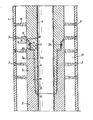
- a production tube (2) Inside a cylindrical casing tube (1) is disposed a production tube (2).
- the casing tube (1) which is located in the production area comprises orifices (3) produced in situ by any suitable connoe means such as shaped charges.
- the production tube consists of tubular elements (4), (5) connected to each other by a seal according to the invention.
- Each element (4), (5) comprises at one of its ends a male thread and a female thread. Only the male end (6) of the upper tube element (4) and the female end (7) of the lower element (5) are shown in the figure.
- the ends of the male (6) and female (7) elements are provided with corresponding conical threads (7a) so that they can be screwed into each other. Sealing and screw-limiting stops (8) are located at the end of the male element and inside the female element.
- Each tube element (4), (5) comprises in the zone (9) at the end of the female element (7) a conical part (10) followed by a cylindrical part (11) then by a shoulder . Near the junction of the parts (10) and (11) is provided on one of the male or female elements (4), (5) a groove 12 in which is arranged an annular sealing member 13. In the mode embodiment shown the groove 12 is formed in the female element (5).
- a channel (14) is formed which follows the contour of the conical parts (10) cylindrical (11) and of the shoulder, which according to the invention is interrupted and divided into two parts by the sealing member (13).
- these soil particles (16) iouent, to hole the production tube (2) erode almost all of its thickness. Indeed, assuming that the particles erode the tip of the conical part 10 in the region R 1 , they will have to cross the metal barrier constituted by the thickness e 1 of the section (4) which is significantly greater than the thickness e 2 of the threaded part (6).
- the jets 16 should, to reach the interior of the production tube, successively cross the thickness e 3 of the female element (5) then the thickness e ' 2 of l 'male element (4), the thickness e' 2 being substantially equal to the thickness e 2 of the threaded part 6
- the particles and other fluid entering the outer end of the channel (14) are stopped by the seal (13), which prevents particle deposition inside. of the joint.
- the conical part 10 makes, with the vertical preferably an angle of 30 ° which allows easy machining of the parts (4) and (5) and which offers maximum resistance to the penetration of particles of ground in the channel (14).
- tube elements provided with seals according to the present invention can be joined to conventional tube elements comprising a corresponding male part and a female part.
Landscapes
- Engineering & Computer Science (AREA)
- General Engineering & Computer Science (AREA)
- Mechanical Engineering (AREA)
- Life Sciences & Earth Sciences (AREA)
- Geology (AREA)
- Mining & Mineral Resources (AREA)
- Physics & Mathematics (AREA)
- Environmental & Geological Engineering (AREA)
- Fluid Mechanics (AREA)
- General Life Sciences & Earth Sciences (AREA)
- Geochemistry & Mineralogy (AREA)
- Earth Drilling (AREA)
Applications Claiming Priority (2)
| Application Number | Priority Date | Filing Date | Title |
|---|---|---|---|
| FR8200171 | 1982-01-08 | ||
| FR8200171A FR2519729A1 (fr) | 1982-01-08 | 1982-01-08 | Joint pour tubes, notamment pour tubes petroliers |
Publications (2)
| Publication Number | Publication Date |
|---|---|
| EP0084009A1 true EP0084009A1 (de) | 1983-07-20 |
| EP0084009B1 EP0084009B1 (de) | 1986-04-09 |
Family
ID=9269783
Family Applications (1)
| Application Number | Title | Priority Date | Filing Date |
|---|---|---|---|
| EP19830400040 Expired EP0084009B1 (de) | 1982-01-08 | 1983-01-07 | Rohrverbindung, insbesondere für Ölfeldröhren |
Country Status (3)
| Country | Link |
|---|---|
| EP (1) | EP0084009B1 (de) |
| DE (1) | DE3362828D1 (de) |
| FR (1) | FR2519729A1 (de) |
Cited By (6)
| Publication number | Priority date | Publication date | Assignee | Title |
|---|---|---|---|---|
| GB2156933A (en) * | 1984-02-21 | 1985-10-16 | Vetco Offshore Ind Inc | Pipe connector |
| NL1017440C2 (nl) * | 2001-02-23 | 2002-08-27 | Pleun Martin Van Der Wel | Samenstel van twee te koppelen elementen, element en koppelstuk dat twee of meer met elkaar verbonden elementen omvat. |
| EP1235019A1 (de) * | 2001-02-23 | 2002-08-28 | Van der Wel, Pleun Martin | Anordnung von zwei zu verbindenen Elementen, Element und Verbindungsstück enthalten zwei oder mehr miteinander verbundene Elemente |
| CZ303442B6 (cs) * | 2001-02-09 | 2012-09-12 | Vallourec Mannesmann Oil & Gas France | Trubkový závitový spoj s lichobežníkovými závity s konvexne zaoblenou plochou |
| CN110319476A (zh) * | 2019-04-30 | 2019-10-11 | 韩金井 | 一种高效利用地热能供暖的井网 |
| CN110319478A (zh) * | 2019-04-30 | 2019-10-11 | 韩金井 | 一种高效利用地热能供暖的高低温组合加热井 |
Citations (5)
| Publication number | Priority date | Publication date | Assignee | Title |
|---|---|---|---|---|
| FR1126723A (fr) * | 1954-07-01 | 1956-11-29 | American Iron & Machine Works | Raccord de conduite |
| FR1223674A (fr) * | 1958-02-26 | 1960-06-20 | American Iron & Machine Works | Raccordement de tuyauterie |
| FR1283955A (fr) * | 1960-12-28 | 1962-02-09 | Vallourec | Joint à double étanchéité |
| FR2389820A1 (de) * | 1977-05-04 | 1978-12-01 | Vetco Inc | |
| US4253687A (en) * | 1979-06-11 | 1981-03-03 | Whiting Oilfield Rental, Inc. | Pipe connection |
-
1982
- 1982-01-08 FR FR8200171A patent/FR2519729A1/fr active Granted
-
1983
- 1983-01-07 EP EP19830400040 patent/EP0084009B1/de not_active Expired
- 1983-01-07 DE DE8383400040T patent/DE3362828D1/de not_active Expired
Patent Citations (5)
| Publication number | Priority date | Publication date | Assignee | Title |
|---|---|---|---|---|
| FR1126723A (fr) * | 1954-07-01 | 1956-11-29 | American Iron & Machine Works | Raccord de conduite |
| FR1223674A (fr) * | 1958-02-26 | 1960-06-20 | American Iron & Machine Works | Raccordement de tuyauterie |
| FR1283955A (fr) * | 1960-12-28 | 1962-02-09 | Vallourec | Joint à double étanchéité |
| FR2389820A1 (de) * | 1977-05-04 | 1978-12-01 | Vetco Inc | |
| US4253687A (en) * | 1979-06-11 | 1981-03-03 | Whiting Oilfield Rental, Inc. | Pipe connection |
Cited By (6)
| Publication number | Priority date | Publication date | Assignee | Title |
|---|---|---|---|---|
| GB2156933A (en) * | 1984-02-21 | 1985-10-16 | Vetco Offshore Ind Inc | Pipe connector |
| CZ303442B6 (cs) * | 2001-02-09 | 2012-09-12 | Vallourec Mannesmann Oil & Gas France | Trubkový závitový spoj s lichobežníkovými závity s konvexne zaoblenou plochou |
| NL1017440C2 (nl) * | 2001-02-23 | 2002-08-27 | Pleun Martin Van Der Wel | Samenstel van twee te koppelen elementen, element en koppelstuk dat twee of meer met elkaar verbonden elementen omvat. |
| EP1235019A1 (de) * | 2001-02-23 | 2002-08-28 | Van der Wel, Pleun Martin | Anordnung von zwei zu verbindenen Elementen, Element und Verbindungsstück enthalten zwei oder mehr miteinander verbundene Elemente |
| CN110319476A (zh) * | 2019-04-30 | 2019-10-11 | 韩金井 | 一种高效利用地热能供暖的井网 |
| CN110319478A (zh) * | 2019-04-30 | 2019-10-11 | 韩金井 | 一种高效利用地热能供暖的高低温组合加热井 |
Also Published As
| Publication number | Publication date |
|---|---|
| FR2519729B1 (de) | 1984-03-23 |
| EP0084009B1 (de) | 1986-04-09 |
| FR2519729A1 (fr) | 1983-07-18 |
| DE3362828D1 (en) | 1986-05-15 |
Similar Documents
| Publication | Publication Date | Title |
|---|---|---|
| CA2323715C (fr) | Assemblage filete de tubes metalliques destines a contenir un fluide corrosif | |
| EP0867596B1 (de) | Gewindeverbinder für Rohre | |
| EP0244044B1 (de) | Akustisches Filter | |
| CA2388688C (fr) | Joint tubulaire filete etanche a la pression exterieure | |
| CA2466791C (fr) | Joint filete tubulaire superieur comprenant au moins un element filete avec levre d'extremite | |
| CA2495883C (fr) | Joint filete tubulaire etanche vis-a-vis du milieu exterieur | |
| CA1074364A (fr) | Joint pour tubes, notamment pour tubes petroliers | |
| CA2489516C (fr) | Joint filete tubulaire renforce pour etancheite amelioree apres expansion plastique | |
| EP1358421B1 (de) | Verschraubbare rohrverbindung mit trapezförmigem gewinde mit konvex gewölbter gewindefläche | |
| FR2526079A2 (fr) | Ensemble a raccord | |
| EP0780617B1 (de) | Schraubverbindung für innenbeschichtete Metallrohre | |
| FR2582772A1 (fr) | Accouplement pour tuyaux | |
| EP0310534A1 (de) | Dichtungsring für feste Teleskopverbindungen | |
| FR2461873A1 (fr) | Joint de tuyauterie resistant a la corrosion | |
| FR2848282A1 (fr) | Procede de realisation d'un joint filete tubulaire etanche vis-a-vis de l'exterieur | |
| FR2851608A1 (fr) | Element d'un train de tiges de forage comportant au moins une zone d'appui, tige de forage et joint d'outil | |
| FR2863029A1 (fr) | Realisation, par expansion plastique, d'un joint tubulaire etanche avec surepaisseur(s) de matiere locale(s) initiale(s) | |
| EP0084009B1 (de) | Rohrverbindung, insbesondere für Ölfeldröhren | |
| FR2863030A1 (fr) | Realisation, par expansion plastique, d'un joint tubulaire etanche avec surface(s) de butee inclinee(s) | |
| EP0187608B1 (de) | Schnellverbindung für unter Druck stehende Flüssigkeitssysteme in denen der Druck 150 bar erreichen kann | |
| EP2795038B1 (de) | Rohrkomponente zum bohren und zum betrieb von ölquellen und resultierende gewindeverbindung | |
| FR2517357A1 (fr) | Tige de forage | |
| CA2536134A1 (fr) | Sellette avec levre d'etancheite | |
| WO2000005526A1 (fr) | Dispositif de jonction bout a bout de conduits | |
| FR2476793A1 (fr) | Joint etanche pour le raccordement de tubes de canalisation de fluides sous pression variable |
Legal Events
| Date | Code | Title | Description |
|---|---|---|---|
| PUAI | Public reference made under article 153(3) epc to a published international application that has entered the european phase |
Free format text: ORIGINAL CODE: 0009012 |
|
| AK | Designated contracting states |
Designated state(s): BE DE FR GB IT NL SE |
|
| 17P | Request for examination filed |
Effective date: 19830706 |
|
| GRAA | (expected) grant |
Free format text: ORIGINAL CODE: 0009210 |
|
| AK | Designated contracting states |
Kind code of ref document: B1 Designated state(s): BE DE FR GB IT NL SE |
|
| REF | Corresponds to: |
Ref document number: 3362828 Country of ref document: DE Date of ref document: 19860515 |
|
| ITF | It: translation for a ep patent filed | ||
| PLBE | No opposition filed within time limit |
Free format text: ORIGINAL CODE: 0009261 |
|
| STAA | Information on the status of an ep patent application or granted ep patent |
Free format text: STATUS: NO OPPOSITION FILED WITHIN TIME LIMIT |
|
| 26N | No opposition filed | ||
| ITTA | It: last paid annual fee | ||
| PGFP | Annual fee paid to national office [announced via postgrant information from national office to epo] |
Ref country code: GB Payment date: 19930104 Year of fee payment: 11 |
|
| PGFP | Annual fee paid to national office [announced via postgrant information from national office to epo] |
Ref country code: SE Payment date: 19930115 Year of fee payment: 11 |
|
| PGFP | Annual fee paid to national office [announced via postgrant information from national office to epo] |
Ref country code: NL Payment date: 19930131 Year of fee payment: 11 |
|
| PGFP | Annual fee paid to national office [announced via postgrant information from national office to epo] |
Ref country code: BE Payment date: 19930212 Year of fee payment: 11 |
|
| PGFP | Annual fee paid to national office [announced via postgrant information from national office to epo] |
Ref country code: DE Payment date: 19930323 Year of fee payment: 11 |
|
| REG | Reference to a national code |
Ref country code: GB Ref legal event code: 732E |
|
| PG25 | Lapsed in a contracting state [announced via postgrant information from national office to epo] |
Ref country code: GB Effective date: 19940107 |
|
| PG25 | Lapsed in a contracting state [announced via postgrant information from national office to epo] |
Ref country code: SE Effective date: 19940108 |
|
| PG25 | Lapsed in a contracting state [announced via postgrant information from national office to epo] |
Ref country code: BE Effective date: 19940131 |
|
| BERE | Be: lapsed |
Owner name: VALLOUREC Effective date: 19940131 |
|
| PG25 | Lapsed in a contracting state [announced via postgrant information from national office to epo] |
Ref country code: NL Effective date: 19940801 |
|
| GBPC | Gb: european patent ceased through non-payment of renewal fee |
Effective date: 19940107 |
|
| NLV4 | Nl: lapsed or anulled due to non-payment of the annual fee | ||
| PG25 | Lapsed in a contracting state [announced via postgrant information from national office to epo] |
Ref country code: DE Effective date: 19941001 |
|
| EUG | Se: european patent has lapsed |
Ref document number: 83400040.8 Effective date: 19940810 |
|
| PGFP | Annual fee paid to national office [announced via postgrant information from national office to epo] |
Ref country code: FR Payment date: 20020115 Year of fee payment: 20 |