EP0084067A2 - Véhicule pour le chargement et excavation - Google Patents
Véhicule pour le chargement et excavation Download PDFInfo
- Publication number
- EP0084067A2 EP0084067A2 EP82100231A EP82100231A EP0084067A2 EP 0084067 A2 EP0084067 A2 EP 0084067A2 EP 82100231 A EP82100231 A EP 82100231A EP 82100231 A EP82100231 A EP 82100231A EP 0084067 A2 EP0084067 A2 EP 0084067A2
- Authority
- EP
- European Patent Office
- Prior art keywords
- arm assembly
- loader
- fluid operated
- wheels
- vehicle
- Prior art date
- Legal status (The legal status is an assumption and is not a legal conclusion. Google has not performed a legal analysis and makes no representation as to the accuracy of the status listed.)
- Ceased
Links
Images
Classifications
-
- E—FIXED CONSTRUCTIONS
- E02—HYDRAULIC ENGINEERING; FOUNDATIONS; SOIL SHIFTING
- E02F—DREDGING; SOIL-SHIFTING
- E02F3/00—Dredgers; Soil-shifting machines
- E02F3/04—Dredgers; Soil-shifting machines mechanically-driven
- E02F3/28—Dredgers; Soil-shifting machines mechanically-driven with digging tools mounted on a dipper- or bucket-arm, i.e. there is either one arm or a pair of arms, e.g. dippers, buckets
- E02F3/34—Dredgers; Soil-shifting machines mechanically-driven with digging tools mounted on a dipper- or bucket-arm, i.e. there is either one arm or a pair of arms, e.g. dippers, buckets with bucket-arms, i.e. a pair of arms, e.g. manufacturing processes, form, geometry, material of bucket-arms directly pivoted on the frames of tractors or self-propelled machines
- E02F3/3402—Dredgers; Soil-shifting machines mechanically-driven with digging tools mounted on a dipper- or bucket-arm, i.e. there is either one arm or a pair of arms, e.g. dippers, buckets with bucket-arms, i.e. a pair of arms, e.g. manufacturing processes, form, geometry, material of bucket-arms directly pivoted on the frames of tractors or self-propelled machines the arms being telescopic
Definitions
- This invention relates to a vehicle of the type comprising a body, a ground engaging propulsion means, including wheels, and/or tracks, one end of a loader arm assembly being mounted on a support part of the body and extending outwardly of one end of the body, for rotation about a first horizontal axis between a first upper position and a second lower position, the first horizontal axis being located horizontally between the axes of rotation of the wheels or between the extremities of the track whichever are provided, and located above a horizontal plane containing the upper edges of the wheels or the upper surface of the tracks nearest said one end of the body, the loader arm assembly carrying at its other end, a loader implement adapted for rotation about a second horizontal axis to enable the implement to be emptied by tipping forwards, fluid operated means being provided to pivot said loader arm assembly about said first horizontal axis, and to cause said rotation of the implement relative to the loader arm assembly about said second horizontal axis, the body having an engine or engines to drive wheels or tracks of the ground engaging pro
- Loader vehicles of the type described have been known for many years. However, an inherent disadvantage is that it is necessary to move the vehicle in order to load the implement. Further, the loader arms are usually relatively long in order to provide sufficient reach during loading. This causes instability when the vehicle is travelling with a loaded implement at the end of the loader arms, distant from the body.
- loader vehicle of the type comprising a body, a ground engaging propulsion means, including wheels, and/or tracks, one end of a loader arm assembly being mounted on a support part of the body and extending outwardly of one end of the body, for rotation about a first horizontal axis between a first upper position and a second lower position, the first horizontal axis being located horizontally between the axes of rotation of the wheels or between the extremities of the track whichever are provided, and located above a horizontal plane containing the upper edges of the wheels or the upper surface of the tracks nearest said one end of the body, the loader arm assembly carrying at its other end, a loader implement adapted for rotation about a second horizontal axis to enable the implement to be emptied by tipping forwards, fluid operated means being provided to pivot said loader arm assembly about said first horizontal axis, and to cause said rotation of the implement relative to the loader arm assembly about said second horizontal axis, the body having an engine or engines to drive wheels or tracks of the ground engaging pro
- the loader implement can be filled, whilst the vehicle is stationery, by extending the implement, or even, where an excavating arm assembly is provided at the other end of the vehicle, whilst the excavating arm is in use.
- the filled implement may be retracted so that the load is nearer to the centre of gravity of the vehicle thus greatly improving the stability of the vehicle when the implement is loaded, especially whilst the vehicle is travelling.
- the load can be lifted to a height greater than the retracted length of the arm assembly to facilitate for example, the emptying of the load into a lorry and/or the load can be emptied from the implement at a greater distance from the vehicle than the retracted length of the arm assembly.
- the booms of the loader arm assembly each comprise first outer and second inner telescoped members, the inner members being movable relative to the outer members by the further fluid operated means which may comprise a hydraulic ram or rams of known type comprising a cylinder and movable piston.
- one hydraulic ram is positioned within each boom, the cylinder of each ram being connected to one telescoped member and the piston of the ram being connected to the other telescoped member.
- the fluid operated means may be located externally of the boom members.
- the operating station may comprise an operator's cab from which each of the fluid operated means of the loader arm assembly and the ground engaging propulsion means may be controlled.
- the body part of the vehicle either side of which the booms extend may comprise a bonnet under which the engine or engines may be housed, and the loader arm assembly, when in its first upper position, may extend above said bonnet.
- the body part may comprise another body part such as an operator's cab, above which the loader arm assembly, when in its first upper position, does not extend.
- the ground engaging propulsion means may comprise at least two pairs of wheels either providing said ground wheels, or wheels engaging and driving said tracks, and the first horizontal axis may be located longitudinally of the vehicle approximately halfway between said pairs of wheels.
- said body part which extends between said pair of booms is located substantially over one of said pairs of wheels.
- the space between said booms may extend for approximately half the retracted length of the booms.
- the loader implement may comprise a loading bucket or a pair of forks or any other loader implement, and the loader implement may be mounted on a mounting part which interconnects the pair of booms.
- the vehicle may be provided with a self-levelling device such as described and claimed in our pending U.K. Application published under number 2,002,220A on the 12th December 1979 so that the implement may be maintained in a particular orientation relative to the ground as the loader arm assembly is moved between its upper and lower positions.
- the vehicle may have a base part of an excavating arm assembly, and pivotally mounted at the other end of the body, the base part having pivoted thereto a dipper arm and an excavating tool being pivotally mounted on the dipper arm, fluid operated means being provided to raise and lower the excavating arm assembly to pivot the dipper arm relative to the base part and to pivot the excavating tool relative to the dipper arm, such an excavating arm assembly is described in detail for example in our previous U.K. Patent 1023175. If desired, in such a vehicle, the excavating arm assembly may also be provided with a self-levelling device.
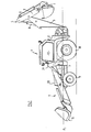
- a loader/excavating vehicle1 whichembodiestheinventionisshown, whichcomprises a body 2 with a loader arm assembly 3 at the front end of the body 2 and an excavating arm assembly 4 at the rear end of the body 2.
- the excavating arm assembly 4 comprises a base part 5 pivotally mounted at one end thereof to the vehicle 1 for rotation about horizontal and vertical axes, and having a dipper arm 6 pivoted thereto at the other end.
- the dipper arm 6 carries an excavating tool comprising a bucket 7.
- Fluid operated means 8 comprising hydraulic rams are provided to cause relative pivotal movement of the various parts of the excavating arm assembly 4.
- the body 2 of the vehicle 1 is mounted on a ground engaging propulsion means including a front pair 9 and a rear pair 10 of drive wheels.
- An engine E is provided beneath a bonnet 33 to provide power to the ground engaging propulsion means and to a pump P of the fluid operated means 8 of the excavating arm assembly 4, and the fluid operated means described below, of the loader arm assembly 3.
- the bonnet 33 is located substantially over the front pair of wheels 9.
- the loader arm assembly 3 is attached to a support part 13 of the body 2 and extends from the front end thereof, the arm assembly 3 being mounted for pivotal movement about a horizontal axis 15.
- the axis 15 is located horizontally approximately halfway between the axis of rotation of the wheels 9, 10 and above a plane P1 containing the uppermost edges of the front wheels 9.
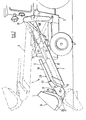
- the loader arm assembly 3 comprises a pair of booms 16, each boom comprising a first outer boom member 17 and a second inner boom member 18 telescopically received in the outer boom member 17.
- the loader arm assembly 3 may be moved between an upper position U shown in chain dotted lines in Figure 2 and a lower position D shown in full lines in Figure 2, wherein the bonnet 33 is received in a space between the booms 16, by fluid operated means comprising two pairs of hydraulic rams 19a, 19b, one ram of each pair being operatively connected to each of the booms 16.
- the operator's cab 12 of the vehicle 1 is located behind the loader arm assembly 3.
- the operator's cab 12 may be positioned at the front of the vehicle 1.
- the booms 16 would extend either side of the cab 12 at least in their lower position D, the cab 12 being received in the space between the booms.
- each of the rams 19b are pivotally connected at one end to a plate 20 attached to one of the outer boom members 17, and are pivotally connected at the other end to a plate 21 rigidly secured to the body 11 of the vehicle.
- the hydraulic rams 19a, 19b are arranged to operate so that by extending or retracting the rams, the loader arm assembly 3 may be moved between its lower D position and upper U position respectively.
- the second inner boom members 18 of each boom 16 are each telescopically extendable and retractable relative to the outer boom member 17 by a further fluid operated means comprising a pair of hydraulic rams 22 one located within each outer boom member 17 and both arranged to operate synchronously.
- the arm assembly 3 has at its outer end 23 a loader bucket assembly 24 secured thereto, comprising a mounting part 25 rigidly interconnecting the inner boom members 18.
- An excavating bucket 26 is shown attached to the mounting part 25 for pivotal movement about a horizontal axis 27, although any other implement such as loading forks may alternatively be provided.
- the bucket 26 may be pivoted between a first loading position L shown in full lines in Figure 2, and a second tipping position T shown in chain dotted lines, by means of a yet further pair of hydraulic rams 28.
- All of the hydraulic rams hereinbefore described are of known type, comprising a piston telescopically received within a cylinder.
- the pistons 31 of the rams 28 are attached to a bracket 29 of the loader bucket 26, and the cylinders 30 of the rams 28 are received in clamping formations 32 of the mounting part 25.
- the loader arm assembly 3 and hence the loader bucket 26 may be lifted or lowered by means of rams 19a, 19b, the loader bucket 26 extended or retracted relative to the boom 16 by means of rams 22 and tipped forwards or backwards by means of rams 28.
- the bucket 26 may therefore be loaded whilst the vehicle is stationary, by extending the ram 22, lifted clear of the ground, retracted relative to the body 2 for stability in transport, and emptied by tipping forwards.
- a vehicle having a single engine E to provide power to the fluid operated means of the excavating arm assembly 4 and the loader arm assembly 3, as well as the ground engaging propulsion wheels 9, 10 has been described, if desired a plurality of engines E may be provided. Further, instead of providing the ground engaging propulsion means with wheels 9, 10, a pair of endless tracks may alternatively be provided. In this case, the tracks will be driven from drive wheels, and the plane P will contain the upper edges of the drive wheels.
- the associated hydraulic control circuitry of the loader arm assembly 3 and/or the excavating arm assembly 4 and the loader bucket 26 or excavating bucket 7 may be provided with a self levelling device such as described and claimed in our co-pending application 2,022,220A which was published on the 12th December 1979.
- loader arm assembly 3 has been described as having a pair of hydraulic rams 22, one located within each boom 16, if desired the bucket 26 or other implement may be extendable or retractable relative to the body 2 by means of one or more rams located externally of the booms 16.
Landscapes
- Engineering & Computer Science (AREA)
- Mechanical Engineering (AREA)
- Mining & Mineral Resources (AREA)
- Civil Engineering (AREA)
- General Engineering & Computer Science (AREA)
- Structural Engineering (AREA)
- Operation Control Of Excavators (AREA)
- Forklifts And Lifting Vehicles (AREA)
- Shovels (AREA)
Priority Applications (1)
| Application Number | Priority Date | Filing Date | Title |
|---|---|---|---|
| EP82100231A EP0084067A3 (fr) | 1982-01-14 | 1982-01-14 | Véhicule pour le chargement et excavation |
Applications Claiming Priority (1)
| Application Number | Priority Date | Filing Date | Title |
|---|---|---|---|
| EP82100231A EP0084067A3 (fr) | 1982-01-14 | 1982-01-14 | Véhicule pour le chargement et excavation |
Publications (2)
| Publication Number | Publication Date |
|---|---|
| EP0084067A2 true EP0084067A2 (fr) | 1983-07-27 |
| EP0084067A3 EP0084067A3 (fr) | 1983-09-28 |
Family
ID=8188821
Family Applications (1)
| Application Number | Title | Priority Date | Filing Date |
|---|---|---|---|
| EP82100231A Ceased EP0084067A3 (fr) | 1982-01-14 | 1982-01-14 | Véhicule pour le chargement et excavation |
Country Status (1)
| Country | Link |
|---|---|
| EP (1) | EP0084067A3 (fr) |
Cited By (4)
| Publication number | Priority date | Publication date | Assignee | Title |
|---|---|---|---|---|
| FR2558500A1 (fr) * | 1984-01-24 | 1985-07-26 | Fontana Jean Francois | Engin de travaux publics polyvalent |
| US6977909B2 (en) | 2000-01-19 | 2005-12-20 | Phonepages Of Sweden, Inc. | Method and apparatus for exchange of information in a communication network |
| US7248862B2 (en) | 2000-01-19 | 2007-07-24 | Sony Ericsson Mobile Communications Ab | Method and apparatus for retrieving calling party information in a mobile communications system |
| US7512692B2 (en) | 2000-10-17 | 2009-03-31 | Sony Ericsson Mobile Communications Ab | Exchange of information in a communication system |
Family Cites Families (8)
| Publication number | Priority date | Publication date | Assignee | Title |
|---|---|---|---|---|
| US2990072A (en) * | 1956-06-08 | 1961-06-27 | Clark Equipment Co | Material handling mechanism |
| GB1023175A (en) * | 1962-09-27 | 1966-03-23 | Bamford Excavators Ltd | Improvements in earth moving implements |
| US3432051A (en) * | 1967-03-29 | 1969-03-11 | Caterpillar Tractor Co | Loader frame for track-type loaders |
| GB2022220B (en) * | 1978-05-16 | 1982-08-04 | Bamford Excavators Ltd | Hydraulic control systems |
| FR2434239A1 (fr) * | 1978-08-23 | 1980-03-21 | Etude Commercialisation Ste Ve | Dispositif convertible de manutention |
| US4266909A (en) * | 1979-01-29 | 1981-05-12 | Westendorf Manufacturing Co. | Means for hydraulic self-leveling of a loader bucket |
| GB2071610B (en) * | 1980-03-14 | 1983-09-21 | Brown Tractors Ltd | Tractor front loader with locking strut |
| GB2079246B (en) * | 1980-07-05 | 1983-11-09 | Bamford Jc Excavators Ltd | Loader/excavator vehicle |
-
1982
- 1982-01-14 EP EP82100231A patent/EP0084067A3/fr not_active Ceased
Cited By (5)
| Publication number | Priority date | Publication date | Assignee | Title |
|---|---|---|---|---|
| FR2558500A1 (fr) * | 1984-01-24 | 1985-07-26 | Fontana Jean Francois | Engin de travaux publics polyvalent |
| EP0150154A3 (fr) * | 1984-01-24 | 1985-08-21 | M.T.P. Société dite: | Engin de travaux publics polyvalent |
| US6977909B2 (en) | 2000-01-19 | 2005-12-20 | Phonepages Of Sweden, Inc. | Method and apparatus for exchange of information in a communication network |
| US7248862B2 (en) | 2000-01-19 | 2007-07-24 | Sony Ericsson Mobile Communications Ab | Method and apparatus for retrieving calling party information in a mobile communications system |
| US7512692B2 (en) | 2000-10-17 | 2009-03-31 | Sony Ericsson Mobile Communications Ab | Exchange of information in a communication system |
Also Published As
| Publication number | Publication date |
|---|---|
| EP0084067A3 (fr) | 1983-09-28 |
Similar Documents
| Publication | Publication Date | Title |
|---|---|---|
| US5807061A (en) | Linkage arrangement for a skid-steer loader | |
| US3215292A (en) | Material handling apparatus-front lift type | |
| US5169278A (en) | Vertical lift loader boom | |
| US4382743A (en) | Loading apparatus with a tiltable and extendable fork carriage mounted thereon | |
| US3967744A (en) | Extensible reach load lifting mechanism | |
| US6796762B2 (en) | Boom and linkage mechanism for skid-steer loader | |
| US4775288A (en) | High-lift loader | |
| US6474933B1 (en) | Extended reach vertical lift boom | |
| US2645369A (en) | Power loader | |
| US20030082040A1 (en) | Low profile lift arm for small skid steer loader | |
| US6325589B1 (en) | Loader with a controlled vertical path of a working implement | |
| US3966070A (en) | Mechanism for loader bucket or forklift mast on a material handling vehicle | |
| US3872991A (en) | Vehicle loader linkage means | |
| US4363409A (en) | Multi-purpose utility vehicle | |
| US3472405A (en) | Material handling apparatus | |
| JPH1046620A (ja) | パワーショベル | |
| US2790568A (en) | Swing-type material moving machine | |
| US3648871A (en) | Vehicle loader | |
| US4431363A (en) | Articulated material handling machine | |
| EP0474210B1 (fr) | Flèche de chargeuse à montée verticale | |
| US3543957A (en) | Fork lift trucks | |
| US3670910A (en) | Mobile load handling or lifting machines | |
| EP1604941A1 (fr) | Machine de chantier autopropulsee | |
| US4329796A (en) | Multi-use excavating and load handling machine | |
| EP0568758A1 (fr) | Elevateur-excavatrice mobile à usage multiple |
Legal Events
| Date | Code | Title | Description |
|---|---|---|---|
| PUAI | Public reference made under article 153(3) epc to a published international application that has entered the european phase |
Free format text: ORIGINAL CODE: 0009012 |
|
| AK | Designated contracting states |
Designated state(s): DE FR IT NL |
|
| PUAL | Search report despatched |
Free format text: ORIGINAL CODE: 0009013 |
|
| AK | Designated contracting states |
Designated state(s): DE FR IT NL |
|
| 17P | Request for examination filed |
Effective date: 19830909 |
|
| STAA | Information on the status of an ep patent application or granted ep patent |
Free format text: STATUS: THE APPLICATION HAS BEEN REFUSED |
|
| 18R | Application refused |
Effective date: 19860405 |
|
| RIN1 | Information on inventor provided before grant (corrected) |
Inventor name: PRIME, DEREK ARTHUR |