EP0084116A2 - Système de synchronisation de l'injection de carburant pour moteur à combustion interne et méthode de commande de celui-ci - Google Patents
Système de synchronisation de l'injection de carburant pour moteur à combustion interne et méthode de commande de celui-ci Download PDFInfo
- Publication number
- EP0084116A2 EP0084116A2 EP82111373A EP82111373A EP0084116A2 EP 0084116 A2 EP0084116 A2 EP 0084116A2 EP 82111373 A EP82111373 A EP 82111373A EP 82111373 A EP82111373 A EP 82111373A EP 0084116 A2 EP0084116 A2 EP 0084116A2
- Authority
- EP
- European Patent Office
- Prior art keywords
- fuel injection
- valve
- engine
- signal
- intake
- Prior art date
- Legal status (The legal status is an assumption and is not a legal conclusion. Google has not performed a legal analysis and makes no representation as to the accuracy of the status listed.)
- Withdrawn
Links
- 239000000446 fuel Substances 0.000 title claims abstract description 195
- 238000002347 injection Methods 0.000 title claims abstract description 156
- 239000007924 injection Substances 0.000 title claims abstract description 156
- 238000002485 combustion reaction Methods 0.000 title claims abstract description 25
- 238000000034 method Methods 0.000 title claims description 14
- 230000005540 biological transmission Effects 0.000 claims description 12
- 230000006835 compression Effects 0.000 claims description 12
- 238000007906 compression Methods 0.000 claims description 12
- 230000006698 induction Effects 0.000 claims description 11
- 239000002826 coolant Substances 0.000 claims description 8
- 238000010438 heat treatment Methods 0.000 claims description 2
- 230000004044 response Effects 0.000 claims description 2
- 230000008054 signal transmission Effects 0.000 claims 2
- 238000000889 atomisation Methods 0.000 abstract description 13
- 239000000203 mixture Substances 0.000 abstract description 10
- 238000010276 construction Methods 0.000 description 4
- XLYOFNOQVPJJNP-UHFFFAOYSA-N water Substances O XLYOFNOQVPJJNP-UHFFFAOYSA-N 0.000 description 3
- 230000001419 dependent effect Effects 0.000 description 2
- 238000001514 detection method Methods 0.000 description 2
- 238000012986 modification Methods 0.000 description 2
- 230000004048 modification Effects 0.000 description 2
- 230000000630 rising effect Effects 0.000 description 2
- 230000001133 acceleration Effects 0.000 description 1
- 230000000903 blocking effect Effects 0.000 description 1
- 238000004891 communication Methods 0.000 description 1
- 238000001816 cooling Methods 0.000 description 1
- 230000007547 defect Effects 0.000 description 1
- 230000006870 function Effects 0.000 description 1
- 239000007788 liquid Substances 0.000 description 1
- 230000007935 neutral effect Effects 0.000 description 1
- 238000005192 partition Methods 0.000 description 1
- 238000011144 upstream manufacturing Methods 0.000 description 1
- 238000010792 warming Methods 0.000 description 1
Images




Classifications
-
- F—MECHANICAL ENGINEERING; LIGHTING; HEATING; WEAPONS; BLASTING
- F02—COMBUSTION ENGINES; HOT-GAS OR COMBUSTION-PRODUCT ENGINE PLANTS
- F02D—CONTROLLING COMBUSTION ENGINES
- F02D41/00—Electrical control of supply of combustible mixture or its constituents
- F02D41/30—Controlling fuel injection
- F02D41/32—Controlling fuel injection of the low pressure type
- F02D41/34—Controlling fuel injection of the low pressure type with means for controlling injection timing or duration
- F02D41/345—Controlling injection timing
-
- F—MECHANICAL ENGINEERING; LIGHTING; HEATING; WEAPONS; BLASTING
- F02—COMBUSTION ENGINES; HOT-GAS OR COMBUSTION-PRODUCT ENGINE PLANTS
- F02M—SUPPLYING COMBUSTION ENGINES IN GENERAL WITH COMBUSTIBLE MIXTURES OR CONSTITUENTS THEREOF
- F02M69/00—Low-pressure fuel-injection apparatus ; Apparatus with both continuous and intermittent injection; Apparatus injecting different types of fuel
- F02M69/04—Injectors peculiar thereto
- F02M69/042—Positioning of injectors with respect to engine, e.g. in the air intake conduit
-
- Y—GENERAL TAGGING OF NEW TECHNOLOGICAL DEVELOPMENTS; GENERAL TAGGING OF CROSS-SECTIONAL TECHNOLOGIES SPANNING OVER SEVERAL SECTIONS OF THE IPC; TECHNICAL SUBJECTS COVERED BY FORMER USPC CROSS-REFERENCE ART COLLECTIONS [XRACs] AND DIGESTS
- Y02—TECHNOLOGIES OR APPLICATIONS FOR MITIGATION OR ADAPTATION AGAINST CLIMATE CHANGE
- Y02T—CLIMATE CHANGE MITIGATION TECHNOLOGIES RELATED TO TRANSPORTATION
- Y02T10/00—Road transport of goods or passengers
- Y02T10/10—Internal combustion engine [ICE] based vehicles
- Y02T10/40—Engine management systems
Definitions
- the present invention relates generally to a fuel injection control system for controlling air-fuel mixture supply for a fuel injection internal combustion engine. More particularly, the invention relates to a fuel injection timing control for controlling the timing of injection of fuel into the engine, especially for the type of engine in which the fuel injection valve is disposed near an intake port and ejects atomized fuel towards an intake valve.
- a representative prior-art method of fuel injection is to direct the fuel injection valve towards the intake valve of each engine cylinder in order to inject the fuel towards the valve head of the intake valve.
- the fuel injected towards the valve head of the intake valve is atomized by colliding with the valve head and the ambient heat in the intake manifold.
- some of the fuel condenses on the valve head and is introduced into the engine combustion chamber in a liquid state. This causes cooling of the spark ignition plug and also results in inaccuracies and irregularities in the air/fuel ratio of the mixture. As a result, engine roughness is increased and/or engine starting characteristics are degraded.
- the present invention is to resolve the above-mentioned defects in the conventional fuel injection system for better engine performance.
- a more specific object of the present invention is to provide a fuel injection timing'control system by which fuel injection takes place at such a time that the injected fuel will be subjected to a significantly high temperature surge of gas in the combustion chamber in order to improve atomization and will be then drawn into the combustion chamber by the vacuum subsequently created therein.
- a fuel injection takes place at the moment of valve overlap, at least under predetermined engine operational conditions.
- an engine revolution sensor is designed to produce a fuel injection signal at a predetermined engine revolution angular position.
- a fuel injection control system for a fuel injection internal combustion engine comprises first means for detecting an engine operating condition and producing a first signal representative of a parameter used in determining the fuel injection amount, second means for detecting the engine crank shaft angular position and producing a second signal each time the crank shaft reaches a predetermined angular position, third means for operating the intake and exhaust valves of the engine in synchronism with the crank shaft rotation so as to provide a predetermined valve overlap period during which both the intake and exhaust valves are open, fourth means for determining the fuel injection amount on the basis of the first signal and producing a control signal for controlling a fuel injection valve, the fourth means being responsive to the second signal for delivering the control signal to the fuel injection valve during the valve overlapping period.
- Fig. 1 there is illustrated a fuel injection system in which each fuel injection valve 10 is located near an intake port 12 of the corresponding engine cylinder 14. As is well known, the intake port 12 is open and closed by an intake valve 16. A spark ignition plug 18 is also provided in the engine cylinder 14 for performing spark ignition in a combustion chamber 20 at a controlled timing. For the sake of clarity, only one combustion chamber 20 and associated equipment are shown in Fig. 1.
- a fuel injection control unit 22 is connected to an electromagnetic actuator 24 of the fuel injection valve 10 for controlling the fuel injection amount as well as the fuel injection timing in accordance with an engine operating condition.
- the fuel injection control unit 22 is connected to a crank angle sensor 26 to receive therefrom a crank reference signal and a crank position signal.
- the crank reference signal is produced each time the crank shaft rotates through a predetermined angle, i.e., every 90° for four-cylinder engine or 60° for six- cylinder engine.
- the crank position signal is produced for every predetermined angular increment of the crank shaft rotation, i.e., 1 0 or 2°.
- the fuel injection control unit 22 is also connected to a load sensor 28, such as an air flow sensor or an intake vacuum sensor, and to an engine idling detector 30 which is responsive to the fully-closed position -of a throttle valve 32.
- the fuel injection control unit 22 is connected to an engine coolant temperature sensor 34 inserted into a water jacket 36 of the engine cylinder.
- the fuel injection control unit 22 calculates the fuel injection amount on the basis of the load on the engine which is represented by the load sensor signal value and the engine speed as derived from the crank angle sensor signals.
- the fuel injection amount calculated on the basis of the engine load parameter and the engine speed parameter may be corrected on the basis of the engine coolant temperature parameter and other engine operational parameters.
- Such fuel injection amount calculation is per se well known to those skilled in the art.
- U.S Patents Nos. 4,199,812 to Klotzner et al and 4,319,327 to Higashiyama et al respectively disclose this method of fuel injection calculation.
- a fuel injection system receives a valve control pulse, the length of which determined the fuel amount delivered to the engine.
- a first counter receives a pulse train whose frequency depends on the air flow rate and this pulse train is admitted for a period defined by the engine speed. The content of the counter is then counted out at a frequency .which is synthesized from operational parameters of the engine, including, in particular, the temperature. For this purpose, there is generated a temperature dependent frequency which is fed to a multiplier circuit which combines this frequency with data derived from a memory to generate an output signal which is further processed to provide the fuel injection pulse for the engine.
- U.S. Patent 4,319,327 discloses a load dependent fuel injection control system, in which a fuel injection rate control system for a fuel injection internal combustion engine produces a basic fuel injection rate signals upon detection of the load on the engine and the engine speed.
- the fuel injection rate signal is modified by the correction values read out from a collection of data indicating various correction values in terms of the engine speed and the engine. load.
- the correction values selected are zero or smaller than a predetermined value
- the fuel injection rate may be controlled to achieve a predetermined air/fuel ratio in the engine through detection of the air/fuel ratio of the mixture produced in the engine.
- the fuel injection control unit 22 also controls the fuel injection timing by controlling transmission of the fuel injection signal.
- the fuel injection is controlled to occur during the valve overlap period wherein both the intake valve 16 and an exhaust valve ⁇ not shown) are open.
- Fig. 2 shows general engine cycle in four-cylinder four-cycle engine in engine idling condition.
- the intake stroke is considered as a period wherein the intake valve opens
- the compression stroke is considered as a period wherein the intake and exhaust valve are both closed
- the combustion stroke is considered as a period wherein combustion is performed with closing of both the intake valve and the exhaust valve
- the exhaust stroke is a period while the exhaust valve is opened.
- each hatched area shows the valve-overlapping period wherein both of intake and exhaust valves open.
- the intake valve opens in the crank shaft angular position about 11 to 20° before exhaust stroke top dead center and closes at the crank angle position about 49 to 60° after the intake stroke bottom dead center.
- the exhaust valve opens at the crank angle position about 50 to 60° before the combustion stroke bottom dead center and closes at the crank angle position 10 to 20° after the exhaust stroke top dead center.
- the fuel injection control unit 22 controls the fuel injection timing in relation to the engine stroke with respect to the valve timing.
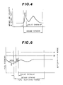
- Fig. 4 shows variation of the intake air velocity flowing into the combustion chamber.
- the flow velocity of the intake air reaches maximum during the valve overlapping period.
- the flow velocity of the intake air influences for the atomization characteristics of the injected fuel and the atomization becomes effective as the intake flow velocity increases. Therefore, it would be understood that, for obtaining good fuel atomization characteristics, the fuel injection timing will be controlled adjacent to or in the valve overlapping period.
- Fig. 3 shows an example of the fuel injection timing control for No. 1 cylinder according to the present invention.
- an initial pulse representative of a crank angle of approximately 10° after top dead center and bottom dead center of the piston stroke is produced with a delay of 104° with respect to the rising edge of the preceding crank reference angle signal which is produced 94° in advance of top or bottom dead center.
- the exhaust valve will be open in a range of the crank shaft angular position of approximately 130° - 370°.
- the intake valve 16 will be open in the range of approximately 349° to 589° of the crank shaft angular position.
- the fuel injection control unit 22 transmits the fuel injection signal for the fuel injection valve 10 during the valve-overlap crank shaft angular position range.
- the transmission timing of the fuel injection signal will vary in according with the setting of the valve-actuating cam shaft and the setting of the valve-overlap range.
- fuel injection timing for the remaining cylinders is controlled similarly to that of the foregoing.
- crank angle sensor 26 in the preferred embodiment is adapted to produce differing crank reference angle signal pulse widths for the compression top dead center of No. 1 cylinder and for that of the other cylinders.
- the crank reference angle signal representative of compression top dead center of the No. 1 cylinder has a longer pulse width, i.e., about 22°, than that of the remaining cylinders, i.e. about 7°.
- Fig. 6 In the view point of the fuel economy, the relationship of the fuel injection timing in engine idling condition is illustrated in Fig. 6. As apparent from Fig. 6, the fuel economy becomes the best at the fuel injection timing slightly before the exhaust stroke top dead center.
- the straight line A shows the fuel economy level in the conventional fuel injection and line B shows that of the conventional fuel injection with pre-heating of the intake air.
- the line C is experimentarily obtained by the fuel injection timing control according to the present invention. From Fig. 6, it becomes apparent that good fuel economy can be obtained by setting the fuel injection timing adjacent the exhaust stroke top dead center of each cylinder.
- the fuel injection timing may be differed from the valve overlapping period when the engine is in warming-up condition for preventing the air/fuel mixture lean by surge gas. In engine warming-up condition, the fuel injection timing may be st at the compression stroke. According to the shown embodiment, the control unit varies the fuel injection timing based on a signal from the engine coolant temperature signal.
- Fig. 7 shows the details of the crank angle sensor 26 applicable for the preferred embodiment of the fuel injection control system.
- a rotor 40 is fixed to the crank shaft 42 for rotation therewith.
- Slits 44 for the crank position signal are arranged radially symmetrically around rotor 40. The spacing between each slit 44 corresponds to 1° of crank shaft rotation.
- slits 46 and 48 are arranged at positions corresponding to predetermined crank shaft angular positions advanced from top dead center of each of the cylinders by a given angle.
- the slit 46 represents compression top dead center of the No. 1 cylinder and has a greater arclength than the slits 48 which represent the compression top dead center positions of the remaining cylinders.
- a photoelectric sensor element 50 faces one surface of the rotor 40 to produce a crank position signal pulse and/or a crank reference angle signal pulse each time one of the slits 44, 46 and 48 passes by sensor 50.
- the fuel injection control unit 22 can determine the cylinder to which to transmit the fuel injection signal. In practice, the fuel injection control unit 22 receives both the crank reference signal and the crank position signal in order to determine the cylinder to which to transmit the fuel injection signal and the transmission timing. In the above-mentioned case, since the crank reference signal representative of the compression top dead center of the No. 1 cylinder has a longer pulse width than the others, the fuel injection control unit 22 can distinguish the No. 1 cylinder top dead center directly and can track the other cylinders in the foregoing order by means of a simple counter shift register, or other switching arrangement.
- the fuel injection valve 10 may be provided a fuel guide groove 52 near the top of a valve needle 51 in order to achieve better atomization characteristics, as shown in Fig. 8.
- a fuel injection valve With such a fuel injection valve, the fuel injected towards the intake valve will will tend to swirl. As a result, the fuel will be satisfactorily atomized and mixed with the intake air to eliminate non-uniformities in the air/fuel mixture.
- the fuel injection timing can be advanced to inject the fuel during the combustion stroke or after suction bottom dead center when engine revolution speed is higher than a given threshold. In this case, the fuel injection should still be performed during the valve-overlap period when the engine is idling or the engine speed is below the given threshold.
- the fuel injection control unit 22 is responsive to the engine speed derived from the crank reference signal and the crank position signal or the engine idling signal from the idling detector 30 to set the fuel injection timing to the valve overlap-range.
- the engine load signal from the engine load sensor 28 may be used by the fuel injection control unit as representative of the engine operating conditions during which fuel injection should occur during the valve-overlap range. If necessary, the fuel injection control unit 22 can be responsive to the released position of a clutch or the neutral position of the transmission to set the fuel injection timing to the valve-overlap range.
- the fuel can be effective atomized by the relatively hot surge of gas flowing back into the air intake passage through the intake valve and can then be introduced into the combustion chamber under low engine load conditions.
- the exhaust gas component of the air/fuel mixture will be held to a minimum in order to provide better engine output characteristics and improve response characteristics to engine acceleration.
- FIG. 9 there is illustrated the second embodiment of the fuel injection control system according to the present invention.
- the air induction system is modified from the foregoing first embodiment and other feature of the control system is constructed similarly to the first embodiment.
- the features and construction elements having the same construction and similar functions are identified by the same reference numerals as referred in the first embodiment.
- the air induction system 100 has an air cleaner 102.
- a warmed air induction passage 104 is connected to an intake duct 106 upstream of the air cleaner 102.
- a swing shutter 108 is provided in .the outlet of the warmed air induction passage and is associated with a diaphragm actuator 110.
- the diaphragm actuator has a chamber 112 pertitioned from the other chamber 114 with an elastically deformable diaphragm 116.
- the chamber 112 is connected to the intake manifold 118 of the air induction system via an intake air temperature sensor 120.
- the intake air temperature sensor 120 incorporates with a thermosensitive valve 122 for establishing or blocking communication between the chamber 112 and the intake manifold.
- thermosensitive valve 122 of the intake air temperature sensor 120 is actuated to open for introduce the vacuum pressure to the chamber 112. If the introduced vacuum in the chamber 112 beyond the set pressure of the diaphragm actuator, which is provided by a set spring 124, to deform the diaphragm 116, the swing shutter 108 is moved with a connecting rod 126 to open. By this, the warmed air flowing through the warmed air induction passage 104 is introduced into the intake duct 106.
- the intake manifold 118 is provided with a water jacket 128 which constitutes a part of the engine coolant recirculation passage.
- the intake air flowing through the intake manifold 118 is warmed by the heat of the engine coolant flowing through the water jacket 128.
- the fuel injection control unit 22 is connected to the crank angle sensor 26, the load sensor 28, a throttle angle position sensor 30 and the engine coolant temperature sensor 34.
- the fuel injection control unit 22 is adapted to control not only the fuel injection amount but also the fuel injection timing.
- the fuel injection control signal produced in the fuel injection control unit 22 is distributed to the electromagnetic actuator 24 of the fuel injection valve 10.
- the fuel injection schedule in this embodiment is modified from the foregoing first embodiment.
- the operation of the fuel injection control unit in this second embodiment will be explained herebelow with reference to the timing chart of Fig. 10 which is illustrated similarly to Fig. 5.
- the valve overlapping at about the exhaust stroke top dead center is assumed about 22° in crank angle.
- the intake valve 16 and exhaust valve 17 overlaps in opening at the crank angle 349° to 371° with respect to the compression stroke top dead center which is assumed as the crank angle is zero.
- the fuel injection signal fed from the fuel injection control unit 22 is a pulse train indicative of the duty cycle of the electromagnetic actuator 24. Therefore, the fuel injection timing as herewith refereed is the timing of the rising of the first fuel injection pulse. According to this second embodiment, the fuel injection timing is set at slightly before the intake valve opening timing. This is intended to some of the fuel injection pulses following to the first one will be fed to the electromagnetic actuator after the intake valve opens, say, in the valve overlapping period.
- timing chart of Fig. 10 concerns to the fuel injection timing control in the engine idling condition. If the engine load is increased which is detected by the load sensor 28, across that in the engine idling condition, the fuel injection- timing will be differed as set forth in the first embodiment.
- the fuel injected is effectively atomized by the substantially high heat of surge gas flowing back to the intake manifold as the intake valve starts opening and by increasing of the flow velocity of the intake air in around the fuel injection valve inthe valve overlapping period.
- the intake air is so warmed as to encourage atomization of the fuel injected, between atomization characteristics can be obtained according to the present invention. This causes reducing of the fluctuation of engine torque or cycle-to-cycle fluctuation in engine idling condition for improve engine stability. Further, by improving the fuel atomization Characteristics, the required fuel amount can be reduced for fuel economy.
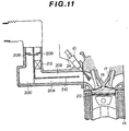
- F ig. 11 shows the third embodiment of the fuel injection control system according to the present invention.
- the shown third embodiment is modified in construction of the intake passage 200.
- the intake passage 200 is separated into a primary passage 202 and a secondary passage 204 with a partition 210.
- Primary and secondary throttle valves 206 and 208 are provided in respective primary and secondary passages 202 and 204 for adjustment of the intake air flow rate.
- a heater unit 212 is inserted in the primary passage downstream of the primary throttle valve 206. This is intended to warm up the intake air particularly in engine idling condition wherein the secondary throttle valve 208 is fully closed. Therefore, the fuel atomization characteristics particularly in engine idling condition.
Landscapes
- Engineering & Computer Science (AREA)
- Chemical & Material Sciences (AREA)
- Combustion & Propulsion (AREA)
- Mechanical Engineering (AREA)
- General Engineering & Computer Science (AREA)
- Electrical Control Of Air Or Fuel Supplied To Internal-Combustion Engine (AREA)
- Output Control And Ontrol Of Special Type Engine (AREA)
- Fuel-Injection Apparatus (AREA)
Applications Claiming Priority (2)
| Application Number | Priority Date | Filing Date | Title |
|---|---|---|---|
| JP56206064A JPS58107871A (ja) | 1981-12-22 | 1981-12-22 | 内燃機関の燃料噴射装置 |
| JP206064/81 | 1981-12-22 |
Publications (2)
| Publication Number | Publication Date |
|---|---|
| EP0084116A2 true EP0084116A2 (fr) | 1983-07-27 |
| EP0084116A3 EP0084116A3 (fr) | 1985-04-10 |
Family
ID=16517244
Family Applications (1)
| Application Number | Title | Priority Date | Filing Date |
|---|---|---|---|
| EP82111373A Withdrawn EP0084116A3 (fr) | 1981-12-22 | 1982-12-08 | Système de synchronisation de l'injection de carburant pour moteur à combustion interne et méthode de commande de celui-ci |
Country Status (3)
| Country | Link |
|---|---|
| US (1) | US4562817A (fr) |
| EP (1) | EP0084116A3 (fr) |
| JP (1) | JPS58107871A (fr) |
Cited By (4)
| Publication number | Priority date | Publication date | Assignee | Title |
|---|---|---|---|---|
| FR2566839A1 (fr) * | 1984-06-29 | 1986-01-03 | Marelli Autronica | Capteur destine a detecter le passage d'un piston ou groupe de pistons d'un moteur a combustion interne par la position du point mort haut |
| US4625697A (en) * | 1983-11-04 | 1986-12-02 | Nissan Motor Company, Limited | Automotive engine control system capable of detecting specific engine operating conditions and projecting subsequent engine operating patterns |
| US4721083A (en) * | 1983-11-04 | 1988-01-26 | Nissan Motor Company, Limited | Electronic control system for internal combustion engine with stall preventive feature and method for performing stall preventive engine control |
| EP0376714A3 (fr) * | 1988-12-28 | 1990-10-31 | Isuzu Motors Limited | Système de commande pour moteur à combustion interne |
Families Citing this family (20)
| Publication number | Priority date | Publication date | Assignee | Title |
|---|---|---|---|---|
| JPS60230531A (ja) * | 1984-04-27 | 1985-11-16 | Mazda Motor Corp | 燃料噴射装置付エンジン |
| JPS60233327A (ja) * | 1984-05-07 | 1985-11-20 | Toyota Motor Corp | 内燃機関の空燃比および点火時期制御装置 |
| JPS62178753A (ja) * | 1986-01-31 | 1987-08-05 | Honda Motor Co Ltd | 内燃エンジンの燃料噴射時期制御方法 |
| JPS62298644A (ja) * | 1986-06-17 | 1987-12-25 | Nissan Motor Co Ltd | 内燃機関の燃料噴射装置 |
| US4911123A (en) * | 1986-09-08 | 1990-03-27 | Ellicott George D | Electronic controller for compression actuated fuel injection system |
| JPH0799106B2 (ja) * | 1987-01-14 | 1995-10-25 | 日産自動車株式会社 | 内燃機関の燃料噴射制御装置 |
| ES2024616B3 (es) * | 1988-11-28 | 1992-03-01 | Siemens Ag | Procedimiento para inyectar combustible en una maquina de combustion interna |
| JP2569174B2 (ja) * | 1989-06-19 | 1997-01-08 | 株式会社日立製作所 | 複数気筒内燃機関の制御装置 |
| JP2990704B2 (ja) * | 1989-08-29 | 1999-12-13 | 三菱電機株式会社 | 内燃機関の燃料噴射装置 |
| US5003952A (en) * | 1990-05-14 | 1991-04-02 | Chrysler Corporation | Sequential variable fuel injection |
| DE19515508C2 (de) * | 1994-04-28 | 1999-01-28 | Hitachi Ltd | Verfahren und Steuervorrichtung zur Antriebssteuerung eines Fahrzeugs mit Verbrennungsmotor und Getriebe |
| JPH10318020A (ja) * | 1997-05-16 | 1998-12-02 | Toyota Motor Corp | 内燃機関の始動時燃料噴射制御装置 |
| JP3736031B2 (ja) * | 1997-05-19 | 2006-01-18 | トヨタ自動車株式会社 | 内燃機関の始動時燃料噴射制御装置 |
| US6178944B1 (en) | 1999-08-31 | 2001-01-30 | Ford Global Technologies, Inc. | Valve cleaning method for direct injection spark ignition engine |
| JP2006177189A (ja) * | 2004-12-21 | 2006-07-06 | Nissan Motor Co Ltd | 内燃機関の排気温度制御装置 |
| JP4701871B2 (ja) * | 2005-06-28 | 2011-06-15 | 日産自動車株式会社 | エンジンの制御装置 |
| JP5783701B2 (ja) * | 2010-10-21 | 2015-09-24 | 日立オートモティブシステムズ株式会社 | 筒内噴射エンジンの制御装置 |
| JP5562910B2 (ja) * | 2011-06-30 | 2014-07-30 | 日立オートモティブシステムズ株式会社 | 筒内噴射式エンジンの制御装置 |
| JP2013096233A (ja) * | 2011-10-28 | 2013-05-20 | Hitachi Automotive Systems Ltd | 内燃機関の燃料噴射装置 |
| KR20230067525A (ko) * | 2021-11-09 | 2023-05-16 | 얀마 홀딩스 주식회사 | 엔진 시스템 |
Family Cites Families (18)
| Publication number | Priority date | Publication date | Assignee | Title |
|---|---|---|---|---|
| US3125085A (en) * | 1964-03-17 | Control of fuel introduction to engine cylinder | ||
| US1999116A (en) * | 1931-04-02 | 1935-04-23 | Bryce Ltd | Internal combustion engine |
| CH434874A (de) * | 1966-04-14 | 1967-04-30 | Huber Robert | Einspritzvorrichtung zum Einspritzen von Kraftstoff in das Saugrohr von fremdgezündeten Brennkraftmaschinen |
| DE1576323A1 (de) * | 1967-12-20 | 1970-06-18 | Porsche Kg | Einspritzbrennkraftmaschine mit Fremdzuendung |
| DE1916167A1 (de) * | 1969-03-28 | 1970-10-15 | Daimler Benz Ag | Vorrichtung zum Regeln eines Verbrennungsmotors |
| US3719177A (en) * | 1970-03-18 | 1973-03-06 | Nippon Denso Co | Signal generating system for internal combustion engines |
| DE2426976A1 (de) * | 1974-06-04 | 1976-02-05 | Wolfgang Klein | Elektronische benzineinspritzung |
| US4100891A (en) * | 1974-08-07 | 1978-07-18 | Rockwell International Corporation | Electronic fuel injection control system |
| JPS51130731A (en) * | 1975-05-12 | 1976-11-13 | Toyota Motor Corp | Fuel injection type internal combustion engine |
| GB1592762A (en) * | 1976-09-21 | 1981-07-08 | Lucas Industries Ltd | Internal combustion engine fuel injection control |
| DE2815701A1 (de) * | 1978-04-12 | 1979-10-25 | Daimler Benz Ag | Fremdgezuendete brennkraftmaschine |
| JPS595769B2 (ja) * | 1978-10-06 | 1984-02-07 | 本田技研工業株式会社 | 高出力型エンジン |
| US4269156A (en) * | 1979-05-01 | 1981-05-26 | The Bendix Corporation | Air/fuel ratio management system with calibration correction for manifold pressure differentials |
| JPS55164761A (en) * | 1979-06-11 | 1980-12-22 | Nissan Motor Co Ltd | Internal-combustion engine |
| JPS5669429A (en) * | 1979-11-12 | 1981-06-10 | Toyota Motor Corp | Fuel injection four-cycle internal combustion engine |
| JPS56159530A (en) * | 1980-05-13 | 1981-12-08 | Diesel Kiki Co Ltd | Injection controller for fuel injection valve of internal- combustion engine |
| JPS57203825A (en) * | 1981-06-10 | 1982-12-14 | Honda Motor Co Ltd | Controlling device for electronic fuel injection of multi cylinder internal-combustion engine |
| JPS5820934A (ja) * | 1981-07-31 | 1983-02-07 | Honda Motor Co Ltd | 電子制御燃料噴射の噴射方法 |
-
1981
- 1981-12-22 JP JP56206064A patent/JPS58107871A/ja active Pending
-
1982
- 1982-11-30 US US06/445,552 patent/US4562817A/en not_active Expired - Fee Related
- 1982-12-08 EP EP82111373A patent/EP0084116A3/fr not_active Withdrawn
Cited By (4)
| Publication number | Priority date | Publication date | Assignee | Title |
|---|---|---|---|---|
| US4625697A (en) * | 1983-11-04 | 1986-12-02 | Nissan Motor Company, Limited | Automotive engine control system capable of detecting specific engine operating conditions and projecting subsequent engine operating patterns |
| US4721083A (en) * | 1983-11-04 | 1988-01-26 | Nissan Motor Company, Limited | Electronic control system for internal combustion engine with stall preventive feature and method for performing stall preventive engine control |
| FR2566839A1 (fr) * | 1984-06-29 | 1986-01-03 | Marelli Autronica | Capteur destine a detecter le passage d'un piston ou groupe de pistons d'un moteur a combustion interne par la position du point mort haut |
| EP0376714A3 (fr) * | 1988-12-28 | 1990-10-31 | Isuzu Motors Limited | Système de commande pour moteur à combustion interne |
Also Published As
| Publication number | Publication date |
|---|---|
| JPS58107871A (ja) | 1983-06-27 |
| EP0084116A3 (fr) | 1985-04-10 |
| US4562817A (en) | 1986-01-07 |
Similar Documents
| Publication | Publication Date | Title |
|---|---|---|
| US4562817A (en) | Fuel injection timing control system for internal combustion engine and control method therefor | |
| CA1250641A (fr) | Reglage d'injection transitoire | |
| US4616617A (en) | Method and arrangement for combustion chamber identification in an internal combustion engine | |
| US4296722A (en) | Control apparatus for an internal combustion engine | |
| US5080068A (en) | Fuel supply control system for internal combustion engine | |
| US5058550A (en) | Method for determining the control values of a multicylinder internal combustion engine and apparatus therefor | |
| US4408279A (en) | Method and apparatus for adjusting the supply of fuel to an internal combustion engine for an acceleration condition | |
| US4955341A (en) | Idle control system for a crankcase scavenged two-stroke engine | |
| US4573443A (en) | Non-synchronous injection acceleration control for a multicylinder internal combustion engine | |
| US4563994A (en) | Fuel injection control apparatus | |
| US4725954A (en) | Apparatus and method for controlling fuel supply to internal combustion engine | |
| US4548178A (en) | Method and apparatus for controlling the air-fuel ratio in an internal-combustion engine | |
| US4389995A (en) | Electronically controlled fuel injection method and apparatus | |
| EP0769613B1 (fr) | Système de commande d'alimentation carburant/air pour moteur à piston à combustion interne | |
| US4736722A (en) | System for automatically defining the minimum setting of an accelerator-controlled valve for supplying an internal combustion engine | |
| US4736719A (en) | System for limiting the maximum speed of an internal combustion engine comprising an electronic injection system | |
| US6371079B1 (en) | Method and arrangement for synchronizing at least two power adjusting elements of an internal combustion engine | |
| JPS59108867A (ja) | 内燃機関の制御方法 | |
| US6912997B2 (en) | Method and arrangement for determining a fuel wall film mass | |
| WO1994001669A1 (fr) | Dispositif et procede de regulation du demarrage de l'injection de carburant dans un moteur a combustion interne | |
| GB2208893A (en) | Process for timing the electronically controlled injection of fuel into an I C engine | |
| US5050565A (en) | Fuel control system for engine | |
| US7140351B2 (en) | Method and device for operating an internal combustion engine | |
| US5103788A (en) | Internal combustion engine ignition timing device | |
| JP2912382B2 (ja) | ポート掃気・燃料噴射式2サイクルエンジン |
Legal Events
| Date | Code | Title | Description |
|---|---|---|---|
| PUAI | Public reference made under article 153(3) epc to a published international application that has entered the european phase |
Free format text: ORIGINAL CODE: 0009012 |
|
| 17P | Request for examination filed |
Effective date: 19821208 |
|
| AK | Designated contracting states |
Designated state(s): DE FR GB |
|
| PUAL | Search report despatched |
Free format text: ORIGINAL CODE: 0009013 |
|
| AK | Designated contracting states |
Designated state(s): DE FR GB |
|
| RAP1 | Party data changed (applicant data changed or rights of an application transferred) |
Owner name: NISSAN MOTOR CO., LTD. |
|
| STAA | Information on the status of an ep patent application or granted ep patent |
Free format text: STATUS: THE APPLICATION IS DEEMED TO BE WITHDRAWN |
|
| 18D | Application deemed to be withdrawn |
Effective date: 19870121 |
|
| RIN1 | Information on inventor provided before grant (corrected) |
Inventor name: ITO, TERUYUKI |