EP0084218A1 - Vérins actionnés par fluide sous pression - Google Patents
Vérins actionnés par fluide sous pression Download PDFInfo
- Publication number
- EP0084218A1 EP0084218A1 EP82306335A EP82306335A EP0084218A1 EP 0084218 A1 EP0084218 A1 EP 0084218A1 EP 82306335 A EP82306335 A EP 82306335A EP 82306335 A EP82306335 A EP 82306335A EP 0084218 A1 EP0084218 A1 EP 0084218A1
- Authority
- EP
- European Patent Office
- Prior art keywords
- fluid pressure
- boot
- actuator
- operable actuator
- tube
- Prior art date
- Legal status (The legal status is an assumption and is not a legal conclusion. Google has not performed a legal analysis and makes no representation as to the accuracy of the status listed.)
- Withdrawn
Links
Images

Classifications
-
- B—PERFORMING OPERATIONS; TRANSPORTING
- B60—VEHICLES IN GENERAL
- B60T—VEHICLE BRAKE CONTROL SYSTEMS OR PARTS THEREOF; BRAKE CONTROL SYSTEMS OR PARTS THEREOF, IN GENERAL; ARRANGEMENT OF BRAKING ELEMENTS ON VEHICLES IN GENERAL; PORTABLE DEVICES FOR PREVENTING UNWANTED MOVEMENT OF VEHICLES; VEHICLE MODIFICATIONS TO FACILITATE COOLING OF BRAKES
- B60T17/00—Component parts, details, or accessories of power brake systems not covered by groups B60T8/00, B60T13/00 or B60T15/00, or presenting other characteristic features
- B60T17/08—Brake cylinders other than ultimate actuators
- B60T17/081—Single service brake actuators
Definitions
- This invention relates to fluid pressure operable actuators and relates especially but not exclusively to fluid pressure operable brake actuators.
- Actuators are known especially for vehicle braking systems which include a main body divided by a pressure responsive member into a pressure chamber and a non-pressure chamber. Application of fluid pressure to the pressure chamber acts via the diaphragm on a push plate carried by an output rod to apply the brakes.
- One type of such actuator is mounted on a brake mechanism by means of a tube via the bore of which the rod is able to engage for example with a member connected to the wedge of a twin wedge brake.
- a fluid pressure operable actuator comprising a housi-ng with a pressure responsive member dividing the housing into a pressure chamber and a non-pressure chamber the non-pressure chamber having an inward projecting tubular spigot, an actuator output rod operatively connected to the pressure responsive member and passing through the tubular spigot and a flexible boot one end of which is sealingly connected to a point on the rod and the other end of which is sealingly retained around the tubular spigot by means of a pressed-in fastening engaging with the internal surface of the tubular spigot, the whole providing a barrier against passage of contaminants between the non-pressure chamber and the tube.
- the fluid pressure operable brake actuator comprises a housing formed-of a first part 1 and a second part 2 between which a peripheral bead 3 of a pressure responsive member in the form of a diaphragm 4 is clamped as shown by a clamping ring 5.
- the arrangement is thus such as to provide a pressure chamber 6 between the diaphragm 4 and the part 2 and a non-pressure chamber 7 between the diaphragm 4 and the part 1.
- an output rod 8 is provided carrying a push plate 9 which bears against the non-pressure side of the diaphragm.
- the rod 8 extends into a mounting tube 10 welded into the part 1 and presents an inwardly projecting tubular spigot 11.
- a moulded flexible rubber boot 12 which has a bead 13 engaging a groove 14 of the rod 8 and a larger diameter bead 15 at its other end sealingly retained against the wall of the part 1 and spigot 11 by a pressed-in retaining member 16.
- the member 16 is tubular and is firmly held in the internal diameter of the tube 10 and has an annular flange 21 for internally engaging the inside of the boot.
- the boot 12 is of re-entrant form such that it executes a rolling motion during movement of the rod 8, away from the fully withdrawn position shown, towards a brake applying position.
- the outward end of the rod 8 is provided with a guiding piece 19 to guide the rod in the bore of the tube 10 and also is provided with a socket 20 to receive the inward end of a rod for actuating a double - wedge brake mechanism into which the outer end of the tube 10 is screwed.
- actuation takes place in known manner by virtue of air pressure applied to chamber 6.
- FIG. 2 shows on greater scale the pressed-in fastening 16 with a portion 22 giving a tight fit in the inner bore of tube 10 and a flange 21 the diamter of which is greater than the outer diameter of the tubular spigot 11 so as to grip the bead 15.
- FIG. 3 shows in diagrammatical form an alternative manner of configuration 24 for the bead 15 and the pressed-in member 16 wherein the member 16 is again provided with an annular flange 23 onto which moulded head 24 can be fitted to retain it in position.
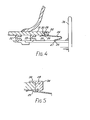
- Fig. 4 shows a diaphragm push plate 36& the non-pressure plate of an actuator such as described above. It is seen that the push rod 25 of the actuator is guided by being carried in tube 31 by a pair of moulded guides 32 and 33 and a flexible resilient boot 24 is provided which like that of Fig. 1 has a smaller diameter end 27 located in a groove 26 on the push rod. However, the larger diameter end of the boot is provided with a thickened radially outwardly extending flange 28 moulded into which there is provided a fastening in the form of an annular clip 29 of brass or other metal which is again a press fit into the spigot formed by the inner end of the tube 31.
- the flange 28 is also provided with an upstanding moulded portion 34 against which the push plate 36 is engageable in the full stroke r - position of the actuator.
- the moulded-in fastening member 29 may extend around the outside diameter of the inner end of the tube 31.
- the material of the flange 28 may be moulded as at 38 to extend around the outer diameter of the inner portion of the tube so that the bead of the gaiter fits on the tube in the manner of a cap.
- the fastening 16 is assembled as a separate item it may be designed for moulding integrally into the bead 15 of the boot and other variants and adaptations of the present concept may now be readily apparent to skilled persons in view of the alternatives described in the foregoing.
Landscapes
- Engineering & Computer Science (AREA)
- Transportation (AREA)
- Mechanical Engineering (AREA)
- Diaphragms And Bellows (AREA)
- Sealing Devices (AREA)
- Braking Arrangements (AREA)
- Actuator (AREA)
Applications Claiming Priority (4)
| Application Number | Priority Date | Filing Date | Title |
|---|---|---|---|
| GB8136343 | 1981-12-02 | ||
| GB8136343 | 1981-12-02 | ||
| GB8206675 | 1982-03-06 | ||
| GB8206675 | 1982-03-06 |
Publications (1)
| Publication Number | Publication Date |
|---|---|
| EP0084218A1 true EP0084218A1 (fr) | 1983-07-27 |
Family
ID=26281438
Family Applications (1)
| Application Number | Title | Priority Date | Filing Date |
|---|---|---|---|
| EP82306335A Withdrawn EP0084218A1 (fr) | 1981-12-02 | 1982-11-29 | Vérins actionnés par fluide sous pression |
Country Status (3)
| Country | Link |
|---|---|
| EP (1) | EP0084218A1 (fr) |
| ES (1) | ES8400949A1 (fr) |
| GB (1) | GB2112068A (fr) |
Cited By (2)
| Publication number | Priority date | Publication date | Assignee | Title |
|---|---|---|---|---|
| EP0542569A1 (fr) * | 1991-11-15 | 1993-05-19 | Knorr-Bremse Systems for Commercial Vehicles Limited | Actionneurs mis en marche par fluide sous pression |
| EP0692651A1 (fr) * | 1994-07-13 | 1996-01-17 | KNORR-BREMSE SYSTEME FÜR NUTZFAHRZEUGE GmbH | Cylindre de frein à disque, en particulier pour véhicules utilitaires |
Citations (1)
| Publication number | Priority date | Publication date | Assignee | Title |
|---|---|---|---|---|
| DE7630598U1 (de) * | 1976-09-30 | 1977-01-13 | Knorr-Bremse Gmbh, 8000 Muenchen | Vorrichtung zur rollbalgbefestigung, insbesondere an der innenwand eines bremszylinders |
-
1982
- 1982-11-29 EP EP82306335A patent/EP0084218A1/fr not_active Withdrawn
- 1982-11-29 GB GB08233946A patent/GB2112068A/en not_active Withdrawn
- 1982-12-02 ES ES517882A patent/ES8400949A1/es not_active Expired
Patent Citations (1)
| Publication number | Priority date | Publication date | Assignee | Title |
|---|---|---|---|---|
| DE7630598U1 (de) * | 1976-09-30 | 1977-01-13 | Knorr-Bremse Gmbh, 8000 Muenchen | Vorrichtung zur rollbalgbefestigung, insbesondere an der innenwand eines bremszylinders |
Cited By (2)
| Publication number | Priority date | Publication date | Assignee | Title |
|---|---|---|---|---|
| EP0542569A1 (fr) * | 1991-11-15 | 1993-05-19 | Knorr-Bremse Systems for Commercial Vehicles Limited | Actionneurs mis en marche par fluide sous pression |
| EP0692651A1 (fr) * | 1994-07-13 | 1996-01-17 | KNORR-BREMSE SYSTEME FÜR NUTZFAHRZEUGE GmbH | Cylindre de frein à disque, en particulier pour véhicules utilitaires |
Also Published As
| Publication number | Publication date |
|---|---|
| ES517882A0 (es) | 1983-11-16 |
| ES8400949A1 (es) | 1983-11-16 |
| GB2112068A (en) | 1983-07-13 |
Similar Documents
| Publication | Publication Date | Title |
|---|---|---|
| US4685686A (en) | Sealing cap for a bolt guide of a spot-type disc brake | |
| US5105727A (en) | Spring brake actuator with an annular edge of a diaphragm sealed between a tubular part of a pressure plate and an actuator rod | |
| US5067391A (en) | Tamper-resistant brake actuator | |
| EP0315463B1 (fr) | Dispositif d'actionnement de frein résistant aux dégradations | |
| US4469337A (en) | Sealing boot of elastomeric material | |
| US4495772A (en) | Brake master cylinder | |
| JPS6080963A (ja) | バキユ−ムブレ−キ用パワ−ブ−スタ | |
| US5320024A (en) | Vacuum brake force booster for automotive vehicles | |
| US5090298A (en) | Brake booster with sealed passage for mounting | |
| US4406213A (en) | Mechanically controlled brake power booster | |
| US4286501A (en) | Servo boosters for vehicle braking systems | |
| US5205205A (en) | Tamper resistant brake actuator | |
| US5433138A (en) | Tamper-resistant brake actuator | |
| US4328738A (en) | Vacuum servo booster | |
| US5320026A (en) | Spring brake actuator with dust guard | |
| US4409885A (en) | Brake booster | |
| GB2088525A (en) | Diaphragm-pressure plate connection in fluid pressure actuator. | |
| GB2216208A (en) | Brake booster | |
| GB2112068A (en) | Actuator with contaminant excluding boot | |
| US4970940A (en) | Vacuum brake booster for automotive vehicles | |
| US5680807A (en) | Vacuum brake booster for motor vehicles | |
| US4198825A (en) | Master cylinder | |
| US4242869A (en) | Master cylinder | |
| JP2002512920A (ja) | 簡素化したストラットをもつブレーキ装置 | |
| EP0040945A1 (fr) | Ensembles de maître-cylindre renforcés pour systèmes de freinage de véhicule |
Legal Events
| Date | Code | Title | Description |
|---|---|---|---|
| PUAI | Public reference made under article 153(3) epc to a published international application that has entered the european phase |
Free format text: ORIGINAL CODE: 0009012 |
|
| AK | Designated contracting states |
Designated state(s): BE DE FR IT NL SE |
|
| STAA | Information on the status of an ep patent application or granted ep patent |
Free format text: STATUS: THE APPLICATION IS DEEMED TO BE WITHDRAWN |
|
| 18D | Application deemed to be withdrawn |
Effective date: 19840703 |
|
| RIN1 | Information on inventor provided before grant (corrected) |
Inventor name: JENNISON, PAUL Inventor name: ROUND, ALAN Inventor name: WHEELER, ARNOLD COURTNEY |