EP0084228A2 - Digitale Farbmodifizierung - Google Patents
Digitale Farbmodifizierung Download PDFInfo
- Publication number
- EP0084228A2 EP0084228A2 EP82306515A EP82306515A EP0084228A2 EP 0084228 A2 EP0084228 A2 EP 0084228A2 EP 82306515 A EP82306515 A EP 82306515A EP 82306515 A EP82306515 A EP 82306515A EP 0084228 A2 EP0084228 A2 EP 0084228A2
- Authority
- EP
- European Patent Office
- Prior art keywords
- color
- look
- summing
- tables
- memory
- Prior art date
- Legal status (The legal status is an assumption and is not a legal conclusion. Google has not performed a legal analysis and makes no representation as to the accuracy of the status listed.)
- Withdrawn
Links
Images

Classifications
-
- H—ELECTRICITY
- H04—ELECTRIC COMMUNICATION TECHNIQUE
- H04N—PICTORIAL COMMUNICATION, e.g. TELEVISION
- H04N1/00—Scanning, transmission or reproduction of documents or the like, e.g. facsimile transmission; Details thereof
- H04N1/46—Colour picture communication systems
- H04N1/56—Processing of colour picture signals
- H04N1/60—Colour correction or control
- H04N1/6027—Correction or control of colour gradation or colour contrast
Definitions
- This invention relates to color adjustment of images, and in particular to real time color adjustment of digital images for display or printing.
- the display art contains many image display processors such as the DeAnza Systems IP5000 Image Processor, the Spatial Data Systems Model 108PTC, the Grinnell GMR-270 Image Processing System, and the Comtal Vision 110 Image Processor. These display processors contain various elements such as a display device, a large digital memory to hold an image, and relatively small look-up tables to modify the image.
- image display processors such as the DeAnza Systems IP5000 Image Processor, the Spatial Data Systems Model 108PTC, the Grinnell GMR-270 Image Processing System, and the Comtal Vision 110 Image Processor.
- These display processors contain various elements such as a display device, a large digital memory to hold an image, and relatively small look-up tables to modify the image.
- Patent 4,154,523 discloses an exposure control means wherein a set of coefficient signals corresponds to a three dimensional color reference system responsive to density signals of the three colors. The coefficient signals are modified to create signals representing matrix values customized to the original density characteristics.
- U.S. Patent 3,144,510 teaches apparatus for compressing color images and in particular in using standard equation color coordinates to manipulate the image. These techniques, however, are generally directed to color correcting a picture.
- the first method used in display systems, provides look-up tables only for each color separation. Typical of this method are the commercial image display processors referred to above. This method gives some flexibility, similar to contrast and exposure control for each separation when printing; but even a simple operation like showing a luminance image cannot be done using look-up tables, without changing the image in memory.
- the second method of adjustment of digital color images used in color correction and display is to provide a single look-up table large enough to handle the modifications.
- the size, cost and complexity of the tables makes it impractical to handle full precision.
- the look-up table would be 24 bits in and 24 bits out for a 3 color system. This is 48 megabytes, exceeding the capacity of practical memory systems. It is possible to reduce the number of bits/pixel/color to reduce the memory size, but this results in less accurate displays.
- Such display systems are known in the prior art, for example, LEXIDATA image display systems. Refer also to U.S. Patent No. 4,236,809 issued December 2, 1980 and assigned to the same assignee as the present invention, for a printing application of the method.
- the present invention is a digital display system including a memory containing representations of three components of a color image (for convenience, these three components are referred to as red, green and blue photographic separation signals, although it should be noted that other representations are suitable such as the standard Y, I and Q television color signals).
- the three components are connected through a network of look-up tables and summing circuits to the red, green and blue display drivers of a suitable display.
- a first summing circuit is connected to the red display driver
- a second summing circuit is connected to the green display driver
- a third summing circuit is connected to the blue display driver.
- Three look-up tables are connected to the red digital representation in memory with one of the look-up tables being connected to the first summing circuit, another of the look-up tables being connected to the second summing circuit and the third look-up table being connected to the third summing circuit.
- groups of three look-up tables are connected to' the green and blue digital representations and each look-up table of each group in turn connected to a different summing circuit. The result is nine look-up tables cross-coupled to three summing circuits to provide selected color adjustments and transformations.
- FIG. 1 a prior art color display system.
- the memory 12 represented by red, green and blue sections, is a typical memory to store the digital representation of a color image.
- Each pixel is represented by 24 bits, 8 bits for each of the red, blue and green colors.
- a typical prior art look-up table is shown in Figure 2. It is divided into 256 elements, one for each grey level per color. Each grey level is represented by an 8 bit word or byte. The 256 bytes are arranged in order of grey level. Thus, the byte 0000,0000 would represent a 0 level grey level and the byte 1111,1111 would represent the high intensity grey level for that particular color.
- the look-up table shown in Figure 2 represents a unit multiplication, that is, every output value resulting from a look-up operation is equal to the input value. Other multiplications and even non-linear functions can be represented by appropriate choice of table entries.
- a particular byte for a particular pixel defines a particular grey level slot for one of the look-up tables. For example, 24 bits of the pixel would identify successively a red level, a blue level and a green level in each of the look-up tables 14, 16 and 18.
- Each level of each of the look-up tables in turn modulates a particular display driver corresponding to the table. That is, the red look-up table 14 would activate a red display driver, the blue look-up table 16 would activate a blue display driver, and the green look-up table 18 would activate the green display driver.
- Each of the display drivers activates a particular color in display 20.
- the red, green and blue are color separations and the levels identified by the look-up tables are the intensities within that particular color separation.
- hue refers to that aspect of perception commonly called “color”; for example “redness” or “greenish-yellowishness”.
- Hue is the aspect that changes most strongly when the wavelength of the stimulus is changed.
- Brightness is that aspect of the perception of a patch of light that varies most strongly when its intensity is changed.
- Saturation refers to the purity of a hue. For example, scarlet is more saturated than pink. Saturation is the aspect that changes most strongly when white light is added to a monochromatic patch.
- color refers to the overall effect of the stimulus, that is, its hue, saturation, and brightness.
- the first need is for a simple technique to be able to easily convert a digital color image to a digital black and white image to make brightness and contrast modifications by changing the values in the look-up tables. Then, it is important to be able to easily return to the original color image to modify the image for color contrast and hue, again by changing values in the look-up tables. It should be noted that many other manipulations may be desired.
- the simple example of showing a luminance image is used to illustrate the improvement of the present invention over prior systems. In the following, we define luminance, then show why prior art systems cannot fulfill this need and how the present invention provides a solution.
- the luminance of a three-color signal can be generally represented by the following formula:
- the significance of the numbers 0.3, 0.6 and 0.1 is that these numbers are the correct proportion of those particular colors to observe a black and white image whose "brightnesses" match those of the color image.
- the three numbers are indications of how sensitive the eye is to the colors blue, green and red.
- the eye is very sensitive to green and therefore a bright green signal would show up as a very bright object.
- a red signal of equal value would be observed at only half the level of brightness of green. This means that if equal signals of red, green and blue are combined, there will not be three times the brightness because the green will be modified by 0.6, the red by 0.3 and the blue by 0.1. This is a phenomenon of the eye. Put in as much red as green, and the red appears only 50 percent as bright as the green.
- Luminance therefore, is a measure of what the eye sees.
- the formula is an indication of how much gray will be on the color TV set display if the color is turned off.
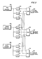
- a simple solution is illustrated in Figure 3.
- a memory is shown having a red segment 22, a green segment 24 and a blue segment 26.
- the red memory segment 22 is connected to a first group of three look-up tables 30, 32 and 34.
- the green memory segment 24 is connected to a second group of three look-up tables, 36, 38 and 40, and the blue memory segment 26 is connected to another group of three look-up tables, 42, 44 and 46.
- the red, green and blue colors are merely exemplary and other combinations are contemplated for use in this invention such as the standard TV color signals.
- Look-up table 30 is connected to a summing circuitry 50
- look-up table 32 is connected to summing circuitry 52
- look-up table 34 is connected to summing circuitry 54.
- each of the look-up tables 36, 38 and 40 connected to the green memory 24 and each of the look-up tables 42, 44, 46 connected to the blue memory 26, are cross-connected to the summing circuitries 50, 52, or 54.
- the summing circuitry 50 related to the red memory 22 is also connected to a component from the green memory 24 and a component from the blue memory 26.
- the summing circuitries 52, 54 are each connected to a component of the red memory, the green memory and the blue memory.
- a composite signal is provided to the red, green and blue display drivers.
- the red display driver for example, is provided with a combination of the red, green and blue signals.
- the red signal provided from circuitry 50 is the sum of the red memory signal through look-up table 30, the green memory signal through look-up table 36, and the blue memory signal through look-up table 42. Also, the portion of the signal that represents red is also a component for the green and blue signals.
- the cross-coupling of the signals allows the look-up tables to provide matrix multiplication, giving where f l -f 9 are the nine look-up tables. It should be noted that the matrix multiplication can be implemented by hardware multipliers as well as look-up tables. It should also be noted that the tables can be loaded with non-linear values.
- This combination provides the power to perform most coordinate transformations. This allows easy color adjustment, as in a TV set, by setting up the luminance image, then adjusting color contrast or saturation, and finally adjusting hue.
- tables 36, 38 and 40 are loaded with values 0.6 times the input and tables 42, 44 and 46 are loaded with values 0.1 times the input.
- color modification As an example of color modification, reference is made to the standard color signal equations for television images taken from COLOR: Theory and Imaging Systems, Society of Photographic Engineers and Engineers.
- the summing circuitry is presumed to include circuitry to add positive or negative numbers, including an extra bit in all tables to signify the sign, if necessary. It should also be noted that a byte in the illustration has been considered to be 8 bits, but that such a system could easily accommodate any other number of bits to represent a tone value.
- This technique can also simulate color correction masks in photographic printing. In photographic printing, however, densities rather than intensities are actually added. To simulate the density effect, the look-up tables would be logarithmic. This would require, therefore, three additional look-up tables 56, 58 and 60 connected to summing circuits 50, 52 and 54 respectively to perform the anti-log function. With this system, it is possible to do color correction, color masking, and other color modification, and changing the hue of the picture just by changing the numbers in the look-up tables, rather than changing all the numbers in the original picture memory.
Landscapes
- Engineering & Computer Science (AREA)
- Multimedia (AREA)
- Signal Processing (AREA)
- Control Of Indicators Other Than Cathode Ray Tubes (AREA)
- Facsimile Image Signal Circuits (AREA)
- Color Image Communication Systems (AREA)
- Processing Of Color Television Signals (AREA)
- Controls And Circuits For Display Device (AREA)
Applications Claiming Priority (2)
| Application Number | Priority Date | Filing Date | Title |
|---|---|---|---|
| US32799281A | 1981-12-07 | 1981-12-07 | |
| US327992 | 1999-06-08 |
Publications (2)
| Publication Number | Publication Date |
|---|---|
| EP0084228A2 true EP0084228A2 (de) | 1983-07-27 |
| EP0084228A3 EP0084228A3 (de) | 1985-05-02 |
Family
ID=23279026
Family Applications (1)
| Application Number | Title | Priority Date | Filing Date |
|---|---|---|---|
| EP82306515A Withdrawn EP0084228A3 (de) | 1981-12-07 | 1982-12-07 | Digitale Farbmodifizierung |
Country Status (3)
| Country | Link |
|---|---|
| EP (1) | EP0084228A3 (de) |
| JP (1) | JPS58106541A (de) |
| IL (1) | IL67202A0 (de) |
Cited By (15)
| Publication number | Priority date | Publication date | Assignee | Title |
|---|---|---|---|---|
| US4679074A (en) * | 1983-03-17 | 1987-07-07 | Canon Kabushiki Kaisha | Color image processing apparatus with a plurality of addressable characteristic conversion tables for compensating for differences in the spectral characteristics of different input devices |
| EP0173032A3 (de) * | 1984-08-28 | 1987-11-11 | Polaroid Corporation | Digitale Farbbildtransformation |
| US4750211A (en) * | 1983-07-29 | 1988-06-07 | Polaroid Corporation | Method and apparatus for image processing with field portions |
| US4763190A (en) * | 1986-06-30 | 1988-08-09 | Xerox Corporation | Digital color correction circuit |
| US4853738A (en) * | 1988-05-02 | 1989-08-01 | Eastman Kodak Company | Color quality improvements for electrophotographic copiers and printers |
| US4862255A (en) * | 1986-12-16 | 1989-08-29 | Victor Company Of Japan, Ltd. | Color correcting circuit for thermal printer selectively outputting a second degree correction operation result and a modified result thereof |
| EP0267566A3 (en) * | 1986-11-10 | 1990-08-01 | Canon Kabushiki Kaisha | Color image recording apparatus |
| US4949135A (en) * | 1989-08-17 | 1990-08-14 | Eastman Kodak Company | Visual based process control apparatus which is based on a near uniform human visual response space |
| US4975769A (en) * | 1987-07-06 | 1990-12-04 | Dai Nippon Insatsu Kaushiki Kaisha | Apparatus for color modification adapted to represent the pictorial image |
| WO1990015404A1 (en) * | 1989-05-30 | 1990-12-13 | Eastman Kodak Company | Apparatus for interfacing video frame store with color display device |
| US4992863A (en) * | 1987-12-22 | 1991-02-12 | Minolta Camera Kabushiki Kaisha | Colored image reading apparatus |
| EP0450867A3 (en) * | 1990-04-02 | 1992-06-17 | Kabushiki Kaisha Toshiba | Hue compensation apparatus for a color hard copy machine |
| EP0591931A1 (de) * | 1992-10-06 | 1994-04-13 | Eastman Kodak Company | Verfahren und Gerät zum Kodieren und Durchführen von multivariablen Farbtransformationen |
| US5434645A (en) * | 1986-04-16 | 1995-07-18 | Canon Kabushiki Kaisha | Color image processing apparatus |
| US5677967A (en) * | 1993-03-10 | 1997-10-14 | R. R. Donnelley & Sons Company | Method of and apparatus for converting between a color appearance space and a colorant space |
Families Citing this family (6)
| Publication number | Priority date | Publication date | Assignee | Title |
|---|---|---|---|---|
| JPH0757008B2 (ja) * | 1983-07-06 | 1995-06-14 | 富士写真フイルム株式会社 | 光量制御信号変換方法 |
| JPS60146574A (ja) * | 1984-01-11 | 1985-08-02 | Hitachi Ltd | カラ−プリンタ−の色変換回路 |
| JPS60216670A (ja) * | 1984-04-12 | 1985-10-30 | Fuji Photo Film Co Ltd | 色修正方式 |
| JPS61111071A (ja) * | 1984-11-06 | 1986-05-29 | Canon Inc | カラ−像形成装置 |
| JPS63316887A (ja) * | 1987-06-20 | 1988-12-26 | 富士通株式会社 | カラ−画像処理プロセッサ |
| IL86107A (en) * | 1988-04-18 | 1991-12-15 | Scitex Corp Ltd | Color conversion display apparatus and method |
Family Cites Families (6)
| Publication number | Priority date | Publication date | Assignee | Title |
|---|---|---|---|---|
| DE1772234C3 (de) * | 1968-04-18 | 1975-11-13 | Dr.-Ing. Rudolf Hell Gmbh, 2300 Kiel | Verfahren zur elektronischen Farbkorrektur |
| GB1315970A (en) * | 1970-02-24 | 1973-05-09 | Ipc Services Ltd | Colour facsimile transmission system |
| US4058828A (en) * | 1975-05-27 | 1977-11-15 | Eastman Kodak Company | Document copying apparatus |
| DE2839187C2 (de) * | 1978-09-08 | 1985-04-25 | Dr.-Ing. Rudolf Hell Gmbh, 2300 Kiel | Verfahren zur Ermittlung der Normfarbwerte von auf einem Farbmonitor dargestellten Farben |
| JPS55142345A (en) * | 1979-04-23 | 1980-11-06 | Dainippon Screen Mfg Co Ltd | Masking operation method in digital color tone control |
| GB2050751B (en) * | 1979-05-30 | 1983-06-29 | Crosfield Electronics Ltd | Image-reproduction apparatus |
-
1982
- 1982-11-08 IL IL67202A patent/IL67202A0/xx unknown
- 1982-11-29 JP JP57210547A patent/JPS58106541A/ja active Pending
- 1982-12-07 EP EP82306515A patent/EP0084228A3/de not_active Withdrawn
Cited By (22)
| Publication number | Priority date | Publication date | Assignee | Title |
|---|---|---|---|---|
| US4679074A (en) * | 1983-03-17 | 1987-07-07 | Canon Kabushiki Kaisha | Color image processing apparatus with a plurality of addressable characteristic conversion tables for compensating for differences in the spectral characteristics of different input devices |
| US4750211A (en) * | 1983-07-29 | 1988-06-07 | Polaroid Corporation | Method and apparatus for image processing with field portions |
| EP0173032A3 (de) * | 1984-08-28 | 1987-11-11 | Polaroid Corporation | Digitale Farbbildtransformation |
| US4839721A (en) * | 1984-08-28 | 1989-06-13 | Polaroid Corporation | Method of and apparatus for transforming color image data on the basis of an isotropic and uniform colorimetric space |
| US5652644A (en) * | 1986-04-16 | 1997-07-29 | Canon Kabushiki Kaisha | Color image processing apparatus which performs color correction in accordance with input color data |
| US5434645A (en) * | 1986-04-16 | 1995-07-18 | Canon Kabushiki Kaisha | Color image processing apparatus |
| US4763190A (en) * | 1986-06-30 | 1988-08-09 | Xerox Corporation | Digital color correction circuit |
| EP0251739A3 (en) * | 1986-06-30 | 1989-08-30 | Xerox Corporation | Colour copiers |
| EP0267566A3 (en) * | 1986-11-10 | 1990-08-01 | Canon Kabushiki Kaisha | Color image recording apparatus |
| EP0606926A1 (de) * | 1986-11-10 | 1994-07-20 | Canon Kabushiki Kaisha | Vorrichtung und Verfahren zur Farbbildaufzeichung |
| US4862255A (en) * | 1986-12-16 | 1989-08-29 | Victor Company Of Japan, Ltd. | Color correcting circuit for thermal printer selectively outputting a second degree correction operation result and a modified result thereof |
| US5278640A (en) * | 1987-07-06 | 1994-01-11 | Dai Nippon Insatsu Kabushiki Kaisha | Color modification utilizing two coefficients |
| US4975769A (en) * | 1987-07-06 | 1990-12-04 | Dai Nippon Insatsu Kaushiki Kaisha | Apparatus for color modification adapted to represent the pictorial image |
| US4992863A (en) * | 1987-12-22 | 1991-02-12 | Minolta Camera Kabushiki Kaisha | Colored image reading apparatus |
| US4853738A (en) * | 1988-05-02 | 1989-08-01 | Eastman Kodak Company | Color quality improvements for electrophotographic copiers and printers |
| EP0429583A1 (de) * | 1989-05-30 | 1991-06-05 | Eastman Kodak Company | Gerät zur schnittstellenbildung eines rasterspeichers mit einer farbanzeigevorrichtung |
| WO1990015404A1 (en) * | 1989-05-30 | 1990-12-13 | Eastman Kodak Company | Apparatus for interfacing video frame store with color display device |
| US4949135A (en) * | 1989-08-17 | 1990-08-14 | Eastman Kodak Company | Visual based process control apparatus which is based on a near uniform human visual response space |
| EP0450867A3 (en) * | 1990-04-02 | 1992-06-17 | Kabushiki Kaisha Toshiba | Hue compensation apparatus for a color hard copy machine |
| US5313290A (en) * | 1990-04-02 | 1994-05-17 | Kabushiki Kaisha Toshiba | Hue compensation apparatus for a color hard copy machine |
| EP0591931A1 (de) * | 1992-10-06 | 1994-04-13 | Eastman Kodak Company | Verfahren und Gerät zum Kodieren und Durchführen von multivariablen Farbtransformationen |
| US5677967A (en) * | 1993-03-10 | 1997-10-14 | R. R. Donnelley & Sons Company | Method of and apparatus for converting between a color appearance space and a colorant space |
Also Published As
| Publication number | Publication date |
|---|---|
| EP0084228A3 (de) | 1985-05-02 |
| JPS58106541A (ja) | 1983-06-24 |
| IL67202A0 (en) | 1983-03-31 |
Similar Documents
| Publication | Publication Date | Title |
|---|---|---|
| CA2043180C (en) | Color correction system employing reference pictures | |
| US5533181A (en) | Image animation for visual training in a simulator | |
| JPS58106541A (ja) | デイジタル的にデイスプレイされる色彩像の色補正用装置及び方法 | |
| US5611030A (en) | Subjectively pleasing color gamut mapping in a color computer graphics system | |
| US4864391A (en) | Image processing apparatus for color correcting an image which can monitor the result of the color correction | |
| Fairchild | Considering the surround in device‐independent color imaging | |
| DE19654715B4 (de) | Verfahren und Vorrichtung zur Farbverarbeitung für eine farbige Anzeigevorrichtung | |
| DE69319979T2 (de) | Bildverarbeitungssystem und Verfahren zur originalgetreuen Wiedergabe der Farben von Objekten auf Negativfilm | |
| JPH0792655B2 (ja) | カラー画像表示方法およびシステム | |
| WO1990000267A1 (en) | Apparatus and method for producing color corrected reproduction of coloured original images | |
| EP1563454A2 (de) | Verfahren zur farbkorrektur digitaler bilder | |
| EP1819143A1 (de) | Farbjustierungseinrichtung und -verfahren | |
| EP0357385A2 (de) | Bildverarbeitungsverfahren und -anordnung | |
| US4602277A (en) | Permanent color correction process using a sampling and an average color determination and a system using this process | |
| WO1991018382A1 (en) | Method and system for displaying color on a computer output device using dithering techniques | |
| Braun et al. | Testing five color‐appearance models for changes in viewing conditions | |
| US6816610B1 (en) | Image processing system | |
| Fairchild | Chromatic adaptation in hard copy/soft copy comparisons | |
| EP1790154A2 (de) | Digitale farbwiedergabetreue | |
| GB2240897A (en) | Color correction and printing system for reproduction of computer-generated images | |
| Neumann et al. | Automatic exposure in computer graphics based on the minimum information loss principle | |
| EP0612054A1 (de) | Unsichtbare Markierung elektronischer Bilder | |
| JP2004364297A (ja) | 画像内の色を補正する方法およびシステム | |
| JPH1117968A (ja) | 画像の色変換方法 | |
| JPH1155688A (ja) | 画像の色変換方法および装置 |
Legal Events
| Date | Code | Title | Description |
|---|---|---|---|
| PUAI | Public reference made under article 153(3) epc to a published international application that has entered the european phase |
Free format text: ORIGINAL CODE: 0009012 |
|
| AK | Designated contracting states |
Designated state(s): DE GB |
|
| PUAL | Search report despatched |
Free format text: ORIGINAL CODE: 0009013 |
|
| AK | Designated contracting states |
Designated state(s): DE GB |
|
| STAA | Information on the status of an ep patent application or granted ep patent |
Free format text: STATUS: THE APPLICATION IS DEEMED TO BE WITHDRAWN |
|
| 18D | Application deemed to be withdrawn |
Effective date: 19860107 |
|
| RIN1 | Information on inventor provided before grant (corrected) |
Inventor name: ROETLING, PAUL G. Inventor name: KNOX, KEITH T. |