EP0084232A1 - Circuits de filtre pour la réduction de la sensibilité à vibration dans des émetteurs de signaux des débitmètres à induction de vortex - Google Patents
Circuits de filtre pour la réduction de la sensibilité à vibration dans des émetteurs de signaux des débitmètres à induction de vortex Download PDFInfo
- Publication number
- EP0084232A1 EP0084232A1 EP82306580A EP82306580A EP0084232A1 EP 0084232 A1 EP0084232 A1 EP 0084232A1 EP 82306580 A EP82306580 A EP 82306580A EP 82306580 A EP82306580 A EP 82306580A EP 0084232 A1 EP0084232 A1 EP 0084232A1
- Authority
- EP
- European Patent Office
- Prior art keywords
- signal
- vibration signal
- vibration
- switches
- filter circuit
- Prior art date
- Legal status (The legal status is an assumption and is not a legal conclusion. Google has not performed a legal analysis and makes no representation as to the accuracy of the status listed.)
- Granted
Links
- 230000035945 sensitivity Effects 0.000 title claims description 4
- 239000003990 capacitor Substances 0.000 claims abstract description 13
- 101150087426 Gnal gene Proteins 0.000 claims 1
- 238000010586 diagram Methods 0.000 description 2
- 230000003321 amplification Effects 0.000 description 1
- 230000005540 biological transmission Effects 0.000 description 1
- 230000000694 effects Effects 0.000 description 1
- 230000008030 elimination Effects 0.000 description 1
- 238000003379 elimination reaction Methods 0.000 description 1
- 238000004519 manufacturing process Methods 0.000 description 1
- 238000000034 method Methods 0.000 description 1
- 238000003199 nucleic acid amplification method Methods 0.000 description 1
Images
Classifications
-
- G—PHYSICS
- G01—MEASURING; TESTING
- G01F—MEASURING VOLUME, VOLUME FLOW, MASS FLOW OR LIQUID LEVEL; METERING BY VOLUME
- G01F1/00—Measuring the volume flow or mass flow of fluid or fluent solid material wherein the fluid passes through a meter in a continuous flow
- G01F1/05—Measuring the volume flow or mass flow of fluid or fluent solid material wherein the fluid passes through a meter in a continuous flow by using mechanical effects
- G01F1/20—Measuring the volume flow or mass flow of fluid or fluent solid material wherein the fluid passes through a meter in a continuous flow by using mechanical effects by detection of dynamic effects of the flow
- G01F1/32—Measuring the volume flow or mass flow of fluid or fluent solid material wherein the fluid passes through a meter in a continuous flow by using mechanical effects by detection of dynamic effects of the flow using swirl flowmeters
- G01F1/325—Means for detecting quantities used as proxy variables for swirl
- G01F1/3287—Means for detecting quantities used as proxy variables for swirl circuits therefor
Definitions
- This invention relates to filter circuits for reducing vibration sensitivity (and noise) in vortex shedding flowmeter signal generators.
- vortex shedding sensors or transmitters are particularly sensitive to vibrations. Such vibrations are sometimes misinterpreted as the vortex shedding frequency or at least represent noise and obstruction to receiving the true vortex shedding frequency.
- a filter circuit for reducing vibration sensitivity in a vortex shedding flowmeter signal generator producing a vortex shedding frequency signal the filter circuit being characterised by:
- a filter circuit forming a preferred embodiment of the present invention and described hereinbelow processes a vibration signal and subtracts it from the vortex shedding frequency signal to provide a shedding frequency signal with reduced or eliminated noise.
- the preferred circuit includes a separate vibration sensor with preamplifier for sensing vibration in the flow stream.
- a vibration signal is provided through a phased locked loop and counter to a channel multiplexer circuit which selectively and sequentially applies a voltage from different sequential parts of the vibration signal to a plurality of capacitors.
- the vortex sensor signal is provided through the multiplexer circuitry wherein the vibration signal at each instant is subtracted from the vortex shedding frequency signal to provide a substantially noise reduced output signal for further amplification.
- the preferred circuit is simple in design and economical to manufacture.
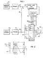
- a connecting line 20 is connected across output lines 22 and 24 respectively of the vortex sensor preamplifier 12 and the vibration sensor preamplifier 16.
- a selector switch S A is manually or automatically operable to select one of the output lines 20 or 24 and connect it to a phase locked loop 30.
- the output line 24 from the vibration sensor preamplifier 16 is shown connected to the loop 30.
- the phase locked loop 30, for example a CA4046B, is connected to the output line 24 of the vibration sensor which maintains a signal in known fashion in case the signal disappears.
- the phase locked loop 30 thus locks into the vibration signal and generates a control signal for tracking a notch filter that is in synchronism with the undesired vibration signal component.
- the vibration signal is multiplied by a number n equal to the number of switches S 1 to S n in a multiplexer 36. This multiplication takes place in the phase locked loop 30 using known circuit components.
- An output of the phase locked loop 30 is connected to a divide-by-n counter 32 which is, for example, a CA4520B.
- the counter 32 divides the signal by the value n and provides it over digital output lines 34 to the multiplexer 36.
- the multiplexer 36 operates to sequentially close the switches S l to S n during a single period of the vibration frequency. If there is no single vibration frequency, the period is divided by the fundamental frequency component of the vibration signal.
- Each of a plurality of capacitors C 1 to C n connected in series with the respective switches S 1 to S n is thus supplied with an average voltage value from the signal during each time increment during which its corresponding switch is closed. Since the capacitors C 1 to C n are in series with the vortex sensor signal coming from the line 22, through suitable and known electronic circuitry, the capacitor voltage is subtracted from the vortex shedding frequency signal.
- the multiplexer 36 comprising the switches S 1 to S n is exemplified by a CD4067B integrated circuit multiplexer.
- Figure 2 shows one period of the fundamental vibration signal 44 whose voltage varies over a total period T.
- the total period is divided by n into time increments dt.
- the average voltage V 1 to V n for each time increment is applied to its corresponding capacitor C 1 to C n by sequential operation of the respective switches S 1 to S n .
- the vibration in the flow is sometimes sufficiently great to produce a vibration signal in the vortex sensor 10 itself and, when this is the case, the switch SA can be switched over to connect to line 20 and provide the vibration signal to the phase locked loop circuit 30.
- the amplifier 40 at the output of the notch filter converts the vortex signal currents in the capacitors C 1 to C n to a voltage type signal to drive following circuitry (not shown).
- the time constant of the resistor R 1 and the capacitors taken individually determines the average of the signal and the bandwidth of the notch. These are chosen typically so that 1/2 ⁇ R 1 C is less than one tenth of the vibration signal to be removed. Also, this determines the lower limit of the desired vortex signal to be amplified. That is, the lower cutoff will be determined by 1/2 ⁇ R 1 C where C is the value of the individual capacitors C 1 to C n .
- An important feature of this apparatus is the tracking of the notch filter to the vibration signal and the sequential elimination of a major portion of the undesired vibration effects by the output of the vortex shedding flow sensor or transmitter.
Landscapes
- Physics & Mathematics (AREA)
- Fluid Mechanics (AREA)
- General Physics & Mathematics (AREA)
- Measuring Volume Flow (AREA)
Applications Claiming Priority (2)
| Application Number | Priority Date | Filing Date | Title |
|---|---|---|---|
| US329539 | 1981-12-10 | ||
| US06/329,539 US4432242A (en) | 1981-12-10 | 1981-12-10 | Tunable notch filter for reducing vibration sensitivity for vortex shedding flowmeter generator |
Publications (2)
| Publication Number | Publication Date |
|---|---|
| EP0084232A1 true EP0084232A1 (fr) | 1983-07-27 |
| EP0084232B1 EP0084232B1 (fr) | 1987-02-04 |
Family
ID=23285881
Family Applications (1)
| Application Number | Title | Priority Date | Filing Date |
|---|---|---|---|
| EP82306580A Expired EP0084232B1 (fr) | 1981-12-10 | 1982-12-09 | Circuits de filtre pour la réduction de la sensibilité à vibration dans des émetteurs de signaux des débitmètres à induction de vortex |
Country Status (5)
| Country | Link |
|---|---|
| US (1) | US4432242A (fr) |
| EP (1) | EP0084232B1 (fr) |
| JP (1) | JPS58154620A (fr) |
| CA (1) | CA1182307A (fr) |
| DE (1) | DE3275403D1 (fr) |
Cited By (3)
| Publication number | Priority date | Publication date | Assignee | Title |
|---|---|---|---|---|
| EP0283030A3 (en) * | 1987-03-19 | 1989-10-11 | Mitsubishi Denki Kabushiki Kaisha | Device for measuring amount of engine suction air |
| EP2385378A1 (fr) * | 2010-04-30 | 2011-11-09 | Rosemount Aerospace Inc. | Procédé pour détecter la dégradation de la performance d'un capteur d'angle via un suivi de vibrations |
| EP2482041A1 (fr) * | 2011-01-31 | 2012-08-01 | KROHNE Messtechnik GmbH | Appareil de mesure de débit à vortex |
Families Citing this family (4)
| Publication number | Priority date | Publication date | Assignee | Title |
|---|---|---|---|---|
| KR920010913B1 (ko) * | 1988-04-19 | 1992-12-24 | 미쓰비시전기 주식회사 | 와 유량계 |
| WO1990004230A1 (fr) * | 1988-10-14 | 1990-04-19 | Engineering Measurements Company | Procede et appareil de traitement de signaux pour debitmetres |
| JPH0648351Y2 (ja) * | 1988-11-14 | 1994-12-12 | オーバル機器工業株式会社 | 渦流量計信号増幅回路 |
| US5710720A (en) * | 1996-04-30 | 1998-01-20 | Board Of Regents Of The University Of Nebraska | Phase lock loop based system and method for decomposing and tracking decomposed frequency components of a signal, with application to vibration compensation system |
Citations (4)
| Publication number | Priority date | Publication date | Assignee | Title |
|---|---|---|---|---|
| US4123940A (en) * | 1977-09-23 | 1978-11-07 | Fischer & Porter Company | Transmission system for vortex-shedding flowmeter |
| DE3006766A1 (de) * | 1979-02-26 | 1980-09-04 | Nissan Motor | Karman-wirbelstroemungsmessgeraet |
| US4306203A (en) * | 1979-03-02 | 1981-12-15 | Matsushita Electric Industrial Co., Ltd. | Filter |
| US4336513A (en) * | 1980-07-02 | 1982-06-22 | Hewlett-Packard Company | Hum reduction circuit |
Family Cites Families (6)
| Publication number | Priority date | Publication date | Assignee | Title |
|---|---|---|---|---|
| US3709034A (en) * | 1971-02-02 | 1973-01-09 | Fischer & Porter Co | Signal conditioner for recovering dominant signals from swirl-type meters |
| US4019384A (en) * | 1974-02-26 | 1977-04-26 | Fischer & Porter Co. | Digital read-out system for external-sensor vortex flowmeter |
| US3982434A (en) * | 1975-03-14 | 1976-09-28 | Eastech, Inc. | Fluid flow signal processing circuit |
| US4094194A (en) * | 1977-02-14 | 1978-06-13 | Fischer & Porter Company | Sensing system for vortex-type flowmeters |
| US4270391A (en) * | 1979-08-24 | 1981-06-02 | Fischer & Porter Co. | Frequency-responsive filter for flowmeter transmission system |
| JPS5698613A (en) * | 1980-01-11 | 1981-08-08 | Nissan Motor Co Ltd | Fuel control device |
-
1981
- 1981-12-10 US US06/329,539 patent/US4432242A/en not_active Expired - Lifetime
-
1982
- 1982-12-08 CA CA000417250A patent/CA1182307A/fr not_active Expired
- 1982-12-09 EP EP82306580A patent/EP0084232B1/fr not_active Expired
- 1982-12-09 DE DE8282306580T patent/DE3275403D1/de not_active Expired
- 1982-12-10 JP JP57215649A patent/JPS58154620A/ja active Granted
Patent Citations (4)
| Publication number | Priority date | Publication date | Assignee | Title |
|---|---|---|---|---|
| US4123940A (en) * | 1977-09-23 | 1978-11-07 | Fischer & Porter Company | Transmission system for vortex-shedding flowmeter |
| DE3006766A1 (de) * | 1979-02-26 | 1980-09-04 | Nissan Motor | Karman-wirbelstroemungsmessgeraet |
| US4306203A (en) * | 1979-03-02 | 1981-12-15 | Matsushita Electric Industrial Co., Ltd. | Filter |
| US4336513A (en) * | 1980-07-02 | 1982-06-22 | Hewlett-Packard Company | Hum reduction circuit |
Cited By (8)
| Publication number | Priority date | Publication date | Assignee | Title |
|---|---|---|---|---|
| EP0283030A3 (en) * | 1987-03-19 | 1989-10-11 | Mitsubishi Denki Kabushiki Kaisha | Device for measuring amount of engine suction air |
| EP2385378A1 (fr) * | 2010-04-30 | 2011-11-09 | Rosemount Aerospace Inc. | Procédé pour détecter la dégradation de la performance d'un capteur d'angle via un suivi de vibrations |
| CN102252693A (zh) * | 2010-04-30 | 2011-11-23 | 罗斯蒙特航天公司 | 通过颤振监控来检测角传感器性能退化的方法 |
| US8606543B2 (en) | 2010-04-30 | 2013-12-10 | Rosemount Aerospace Inc. | Method to detect angle sensor performance degradation through dither monitoring |
| CN102252693B (zh) * | 2010-04-30 | 2015-11-25 | 罗斯蒙特航天公司 | 通过颤振监控来检测角传感器性能退化的方法 |
| US9383249B2 (en) | 2010-04-30 | 2016-07-05 | Rosemount Aerospace Inc. | Method to detect angle sensor performance degradation through dither monitoring |
| EP2482041A1 (fr) * | 2011-01-31 | 2012-08-01 | KROHNE Messtechnik GmbH | Appareil de mesure de débit à vortex |
| CN102680030A (zh) * | 2011-01-31 | 2012-09-19 | 克洛纳测量技术有限公司 | 涡流流量计 |
Also Published As
| Publication number | Publication date |
|---|---|
| DE3275403D1 (en) | 1987-03-12 |
| JPS635686B2 (fr) | 1988-02-04 |
| EP0084232B1 (fr) | 1987-02-04 |
| JPS58154620A (ja) | 1983-09-14 |
| US4432242A (en) | 1984-02-21 |
| CA1182307A (fr) | 1985-02-12 |
Similar Documents
| Publication | Publication Date | Title |
|---|---|---|
| EP0187407A1 (fr) | Traitement de signaux qui correspondent à la fréquence d'émission de tourbillons | |
| KR100186887B1 (ko) | 전자유량계 및 유량의 전자측정방법 | |
| EP1085301B1 (fr) | Débitmètre à tourbillons | |
| EP0791807A3 (fr) | Appareil de mesure de la différence de phase entre deux signaux d'entrée | |
| EP1660844B1 (fr) | Procede et systeme de filtre de debitmetre | |
| EP0084232A1 (fr) | Circuits de filtre pour la réduction de la sensibilité à vibration dans des émetteurs de signaux des débitmètres à induction de vortex | |
| GB2201785A (en) | Electromagnetic flow meter | |
| JP4435309B2 (ja) | 渦流量計および質量流計に関する出力値を計算する方法 | |
| EP0677922A2 (fr) | Filtre passe bas à réponse rapide | |
| EP0135081A2 (fr) | Réduction de bruit par interpolation linéaire utilisant un circuit amplificateur à double fonction | |
| SE503015C2 (sv) | Förfarande för driftidentifiering av en mätvärdesomformare vid magnetisk-induktiv genomströmningsmätning och magnetisk-induktiv genomströmningsmätare för genomförande av förfarandet | |
| EP0028027B1 (fr) | Dispositif de mesure de la vitesse d'écoulement de fluides | |
| JP2932710B2 (ja) | 質量流量計 | |
| EP0084231B1 (fr) | Circuits pour des débitmètres à induction de vortex | |
| US4283958A (en) | Magnetic flowmeter having automatic ranging | |
| WO2004029558A2 (fr) | Circuit de detection d'ecoulement | |
| JP2856521B2 (ja) | 電磁流量計 | |
| JP3031387B2 (ja) | 渦流量計 | |
| EP0029239A1 (fr) | Circuit de filtrage passe-bas et procédé d'utilisation de ce circuit | |
| KR940008903B1 (ko) | 변류기의 보상장치 | |
| JP2932708B2 (ja) | 質量流量計 | |
| EP0056516B1 (fr) | Multiplicateur à convertisseur de fréquence | |
| CA1062037A (fr) | Systeme de detection de debitmetre de tourbillon | |
| US3717027A (en) | Digital display distance log | |
| JPH04284600A (ja) | 信号伝送装置 |
Legal Events
| Date | Code | Title | Description |
|---|---|---|---|
| PUAI | Public reference made under article 153(3) epc to a published international application that has entered the european phase |
Free format text: ORIGINAL CODE: 0009012 |
|
| AK | Designated contracting states |
Designated state(s): DE FR GB IT |
|
| 17P | Request for examination filed |
Effective date: 19831203 |
|
| ITF | It: translation for a ep patent filed | ||
| GRAA | (expected) grant |
Free format text: ORIGINAL CODE: 0009210 |
|
| AK | Designated contracting states |
Kind code of ref document: B1 Designated state(s): DE FR GB IT |
|
| REF | Corresponds to: |
Ref document number: 3275403 Country of ref document: DE Date of ref document: 19870312 |
|
| ET | Fr: translation filed | ||
| PLBE | No opposition filed within time limit |
Free format text: ORIGINAL CODE: 0009261 |
|
| STAA | Information on the status of an ep patent application or granted ep patent |
Free format text: STATUS: NO OPPOSITION FILED WITHIN TIME LIMIT |
|
| 26N | No opposition filed | ||
| REG | Reference to a national code |
Ref country code: GB Ref legal event code: 732 |
|
| ITTA | It: last paid annual fee | ||
| PGFP | Annual fee paid to national office [announced via postgrant information from national office to epo] |
Ref country code: FR Payment date: 19961115 Year of fee payment: 15 |
|
| PGFP | Annual fee paid to national office [announced via postgrant information from national office to epo] |
Ref country code: DE Payment date: 19961122 Year of fee payment: 15 |
|
| PGFP | Annual fee paid to national office [announced via postgrant information from national office to epo] |
Ref country code: GB Payment date: 19961128 Year of fee payment: 15 |
|
| PG25 | Lapsed in a contracting state [announced via postgrant information from national office to epo] |
Ref country code: GB Free format text: LAPSE BECAUSE OF NON-PAYMENT OF DUE FEES Effective date: 19971209 |
|
| PG25 | Lapsed in a contracting state [announced via postgrant information from national office to epo] |
Ref country code: FR Free format text: THE PATENT HAS BEEN ANNULLED BY A DECISION OF A NATIONAL AUTHORITY Effective date: 19971231 |
|
| GBPC | Gb: european patent ceased through non-payment of renewal fee |
Effective date: 19971209 |
|
| PG25 | Lapsed in a contracting state [announced via postgrant information from national office to epo] |
Ref country code: DE Free format text: LAPSE BECAUSE OF NON-PAYMENT OF DUE FEES Effective date: 19980901 |
|
| REG | Reference to a national code |
Ref country code: FR Ref legal event code: ST |