EP0084238A1 - Interrupteur à vide - Google Patents
Interrupteur à vide Download PDFInfo
- Publication number
- EP0084238A1 EP0084238A1 EP82306701A EP82306701A EP0084238A1 EP 0084238 A1 EP0084238 A1 EP 0084238A1 EP 82306701 A EP82306701 A EP 82306701A EP 82306701 A EP82306701 A EP 82306701A EP 0084238 A1 EP0084238 A1 EP 0084238A1
- Authority
- EP
- European Patent Office
- Prior art keywords
- insulating
- vacuum
- envelope
- metallic
- unglazed
- Prior art date
- Legal status (The legal status is an assumption and is not a legal conclusion. Google has not performed a legal analysis and makes no representation as to the accuracy of the status listed.)
- Granted
Links
- WABPQHHGFIMREM-UHFFFAOYSA-N lead(0) Chemical compound [Pb] WABPQHHGFIMREM-UHFFFAOYSA-N 0.000 claims abstract description 42
- 239000000919 ceramic Substances 0.000 claims abstract description 41
- 238000007789 sealing Methods 0.000 claims description 36
- 239000003973 paint Substances 0.000 claims description 16
- 239000002966 varnish Substances 0.000 claims description 15
- 239000005011 phenolic resin Substances 0.000 claims description 3
- 239000011347 resin Substances 0.000 claims description 3
- 229920005989 resin Polymers 0.000 claims description 3
- JOYRKODLDBILNP-UHFFFAOYSA-N Ethyl urethane Chemical compound CCOC(N)=O JOYRKODLDBILNP-UHFFFAOYSA-N 0.000 claims description 2
- 239000003822 epoxy resin Substances 0.000 claims description 2
- 229920000647 polyepoxide Polymers 0.000 claims description 2
- 239000003344 environmental pollutant Substances 0.000 abstract description 3
- 231100000719 pollutant Toxicity 0.000 abstract description 3
- 238000005219 brazing Methods 0.000 description 15
- RYGMFSIKBFXOCR-UHFFFAOYSA-N Copper Chemical compound [Cu] RYGMFSIKBFXOCR-UHFFFAOYSA-N 0.000 description 9
- 229910052802 copper Inorganic materials 0.000 description 9
- 239000010949 copper Substances 0.000 description 9
- 239000000463 material Substances 0.000 description 8
- 238000000034 method Methods 0.000 description 8
- 230000008569 process Effects 0.000 description 8
- 229910045601 alloy Inorganic materials 0.000 description 5
- 239000000956 alloy Substances 0.000 description 5
- 230000002093 peripheral effect Effects 0.000 description 5
- 239000000853 adhesive Substances 0.000 description 4
- 230000001070 adhesive effect Effects 0.000 description 4
- 238000004519 manufacturing process Methods 0.000 description 4
- 238000010583 slow cooling Methods 0.000 description 4
- ZAMOUSCENKQFHK-UHFFFAOYSA-N Chlorine atom Chemical compound [Cl] ZAMOUSCENKQFHK-UHFFFAOYSA-N 0.000 description 3
- 229910001030 Iron–nickel alloy Inorganic materials 0.000 description 3
- 239000000460 chlorine Substances 0.000 description 3
- 229910052801 chlorine Inorganic materials 0.000 description 3
- 238000001035 drying Methods 0.000 description 3
- 238000010304 firing Methods 0.000 description 3
- 239000010935 stainless steel Substances 0.000 description 3
- 229910001220 stainless steel Inorganic materials 0.000 description 3
- 229910000881 Cu alloy Inorganic materials 0.000 description 2
- XEEYBQQBJWHFJM-UHFFFAOYSA-N Iron Chemical compound [Fe] XEEYBQQBJWHFJM-UHFFFAOYSA-N 0.000 description 2
- PNEYBMLMFCGWSK-UHFFFAOYSA-N aluminium oxide Inorganic materials [O-2].[O-2].[O-2].[Al+3].[Al+3] PNEYBMLMFCGWSK-UHFFFAOYSA-N 0.000 description 2
- 238000007796 conventional method Methods 0.000 description 2
- 238000005260 corrosion Methods 0.000 description 2
- 230000007797 corrosion Effects 0.000 description 2
- 229910052751 metal Inorganic materials 0.000 description 2
- 239000002184 metal Substances 0.000 description 2
- NOTVAPJNGZMVSD-UHFFFAOYSA-N potassium monoxide Inorganic materials [K]O[K] NOTVAPJNGZMVSD-UHFFFAOYSA-N 0.000 description 2
- VEXZGXHMUGYJMC-UHFFFAOYSA-M Chloride anion Chemical compound [Cl-] VEXZGXHMUGYJMC-UHFFFAOYSA-M 0.000 description 1
- 229910020630 Co Ni Inorganic materials 0.000 description 1
- 229910002440 Co–Ni Inorganic materials 0.000 description 1
- 239000004593 Epoxy Substances 0.000 description 1
- KKCBUQHMOMHUOY-UHFFFAOYSA-N Na2O Inorganic materials [O-2].[Na+].[Na+] KKCBUQHMOMHUOY-UHFFFAOYSA-N 0.000 description 1
- 229910017709 Ni Co Inorganic materials 0.000 description 1
- 229910003267 Ni-Co Inorganic materials 0.000 description 1
- 229910003262 Ni‐Co Inorganic materials 0.000 description 1
- 229910018107 Ni—Ca Inorganic materials 0.000 description 1
- 238000005299 abrasion Methods 0.000 description 1
- 230000004888 barrier function Effects 0.000 description 1
- KGBXLFKZBHKPEV-UHFFFAOYSA-N boric acid Chemical compound OB(O)O KGBXLFKZBHKPEV-UHFFFAOYSA-N 0.000 description 1
- 239000004327 boric acid Substances 0.000 description 1
- 230000008859 change Effects 0.000 description 1
- FZFYOUJTOSBFPQ-UHFFFAOYSA-M dipotassium;hydroxide Chemical compound [OH-].[K+].[K+] FZFYOUJTOSBFPQ-UHFFFAOYSA-M 0.000 description 1
- NTGONJLAOZZDJO-UHFFFAOYSA-M disodium;hydroxide Chemical compound [OH-].[Na+].[Na+] NTGONJLAOZZDJO-UHFFFAOYSA-M 0.000 description 1
- 239000011521 glass Substances 0.000 description 1
- 238000010438 heat treatment Methods 0.000 description 1
- 238000009413 insulation Methods 0.000 description 1
- 229910052742 iron Inorganic materials 0.000 description 1
- 150000002739 metals Chemical class 0.000 description 1
- 239000004033 plastic Substances 0.000 description 1
- 239000002994 raw material Substances 0.000 description 1
- 230000001629 suppression Effects 0.000 description 1
- 230000008646 thermal stress Effects 0.000 description 1
Images
Classifications
-
- H—ELECTRICITY
- H01—ELECTRIC ELEMENTS
- H01H—ELECTRIC SWITCHES; RELAYS; SELECTORS; EMERGENCY PROTECTIVE DEVICES
- H01H33/00—High-tension or heavy-current switches with arc-extinguishing or arc-preventing means
- H01H33/60—Switches wherein the means for extinguishing or preventing the arc do not include separate means for obtaining or increasing flow of arc-extinguishing fluid
- H01H33/66—Vacuum switches
-
- H—ELECTRICITY
- H01—ELECTRIC ELEMENTS
- H01H—ELECTRIC SWITCHES; RELAYS; SELECTORS; EMERGENCY PROTECTIVE DEVICES
- H01H33/00—High-tension or heavy-current switches with arc-extinguishing or arc-preventing means
- H01H33/60—Switches wherein the means for extinguishing or preventing the arc do not include separate means for obtaining or increasing flow of arc-extinguishing fluid
- H01H33/66—Vacuum switches
- H01H33/662—Housings or protective screens
- H01H33/66261—Specific screen details, e.g. mounting, materials, multiple screens or specific electrical field considerations
-
- H—ELECTRICITY
- H01—ELECTRIC ELEMENTS
- H01H—ELECTRIC SWITCHES; RELAYS; SELECTORS; EMERGENCY PROTECTIVE DEVICES
- H01H33/00—High-tension or heavy-current switches with arc-extinguishing or arc-preventing means
- H01H33/60—Switches wherein the means for extinguishing or preventing the arc do not include separate means for obtaining or increasing flow of arc-extinguishing fluid
- H01H33/66—Vacuum switches
- H01H33/662—Housings or protective screens
- H01H33/66207—Specific housing details, e.g. sealing, soldering or brazing
- H01H2033/66215—Details relating to the soldering or brazing of vacuum switch housings
-
- H—ELECTRICITY
- H01—ELECTRIC ELEMENTS
- H01H—ELECTRIC SWITCHES; RELAYS; SELECTORS; EMERGENCY PROTECTIVE DEVICES
- H01H33/00—High-tension or heavy-current switches with arc-extinguishing or arc-preventing means
- H01H33/60—Switches wherein the means for extinguishing or preventing the arc do not include separate means for obtaining or increasing flow of arc-extinguishing fluid
- H01H33/66—Vacuum switches
- H01H33/662—Housings or protective screens
- H01H33/66207—Specific housing details, e.g. sealing, soldering or brazing
- H01H2033/66223—Details relating to the sealing of vacuum switch housings
-
- H—ELECTRICITY
- H01—ELECTRIC ELEMENTS
- H01H—ELECTRIC SWITCHES; RELAYS; SELECTORS; EMERGENCY PROTECTIVE DEVICES
- H01H33/00—High-tension or heavy-current switches with arc-extinguishing or arc-preventing means
- H01H33/60—Switches wherein the means for extinguishing or preventing the arc do not include separate means for obtaining or increasing flow of arc-extinguishing fluid
- H01H33/66—Vacuum switches
- H01H33/662—Housings or protective screens
- H01H33/66207—Specific housing details, e.g. sealing, soldering or brazing
- H01H2033/6623—Details relating to the encasing or the outside layers of the vacuum switch housings
-
- H—ELECTRICITY
- H01—ELECTRIC ELEMENTS
- H01H—ELECTRIC SWITCHES; RELAYS; SELECTORS; EMERGENCY PROTECTIVE DEVICES
- H01H33/00—High-tension or heavy-current switches with arc-extinguishing or arc-preventing means
- H01H33/60—Switches wherein the means for extinguishing or preventing the arc do not include separate means for obtaining or increasing flow of arc-extinguishing fluid
- H01H33/66—Vacuum switches
- H01H33/662—Housings or protective screens
- H01H33/66261—Specific screen details, e.g. mounting, materials, multiple screens or specific electrical field considerations
- H01H2033/66292—Details relating to the use of multiple screens in vacuum switches
-
- H—ELECTRICITY
- H01—ELECTRIC ELEMENTS
- H01H—ELECTRIC SWITCHES; RELAYS; SELECTORS; EMERGENCY PROTECTIVE DEVICES
- H01H33/00—High-tension or heavy-current switches with arc-extinguishing or arc-preventing means
- H01H33/60—Switches wherein the means for extinguishing or preventing the arc do not include separate means for obtaining or increasing flow of arc-extinguishing fluid
- H01H33/66—Vacuum switches
- H01H33/662—Housings or protective screens
- H01H33/66207—Specific housing details, e.g. sealing, soldering or brazing
Definitions
- the present invention relates to a vacuum interrupter, particularly to a vacuum interrupter of which a vacuum envelope comprises a metallic member and an insulating ceramic member.
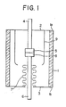
- a vacuum envelope of a conventional vacuum interrupter comprises a circular insulating cylinder 1 as an insulating member, and circular metallic end plates 2 and 3. as metallic members.
- the insulating cylinder 1 is made. of insulating ceramics such as alumina ceramics glazed on an outer surface, or of crystalized glass.
- the metallic end plates 2 and 3 are made of a Fe-Ni-Ca alloy or a Fe-Ni alloy.
- An electric stationary lead rod 4 is secured to the metallic end plate 2 coaxially to the insulating cylinder 1 in such a manner that it enters in the insulating cylinder 1 in vaccum-tightness via a circular aperture at a center of the one metallic end plate 2.
- a stationary contact 5 is secured on an inside end of the stationary lead rod 4.
- An electric movable lead rod 6 is inserted in the insulating cylinder 1 via a circular aperture at a center of the other metallic end plate 3.
- the movable lead rod 6 is supported in vacuum-tightness by bellows 7, being coaxial to the insulating cylinder 1.
- a movable contact 8 is secured on an inside end of the movable lead rod 6, a movable contact 8 is secured.
- the stationary and movable contacts 5 and 8 are separable by an axial movement of the movable lead rod 6.
- a substantially circular cylindrical arc shield 9 is provided coaxially to the insulating cylinder 1 around the stationary and movable contacts 5 and 8, projecting from the one metallic end plate 2.
- the insulating cylinder 1 is made of insulating ceramics glazed on the outer surface, it is manufactured through the following steps.
- the manufacturing steps comprise the step in which a raw materials of glaze is applied by conventional method to an outer periphery of a cylinder made of unglazed insulating ceramics, and the subsequent step in which the cylinder applied with glazing materials is fired to change the applied glazing materials into an impervious glassy film of glaze.
- This glassy film is capable of protecting the outer periphery of the insulating cylinder 1 from adsorbing moisture and pollutant, thereby preventing an insulating performance of the outer periphery of the insulating cylinder 1 from being reduced.
- both of annular end surfaces la and lb remains unglazed even in the course of forming the glassy film of glaze on the outer periphery of the insulating cylinder 1 by firing.
- Metallized layers (not shown) are formed on the unglazed annular end surfaces la and lb, respectively.
- the metallic end plates 2 and 3 are directly brazed by conventional method to the metallized layers, respectively.
- the insulating cylinder 1 generally, insulating members for a vacuum envelope of a vacuum interrupter.
- the above glazing materials include some high vapor pressure components such as anhydrous boric acid B 2 O 3 , sodium monoxide Na 2 O and potassium monoxide K20, they are vaporized in a step of vacuum brazing for a vacuum interrupter (at 900°C-1050°C) in a vacuum furnace to be chamber deposited on vacuum- ⁇ -side surfaces of the insulating members for the vacuum envelope, which reduces an chamber insulating performance of the vacuum- ⁇ -side surfaces of the insulating members, and to be deposited on surfaces of interiors of the vacuum furnace, which causes to hinder the continuing operation of the vacuum furnace.
- a vacuum interrupter at 900°C-1050°C
- the surface of the unglazed insulating ceramics adsorbs moisture and pollutant, which causes insulating performance of the insulating member for the vacuum interrupter to lower, and which causes a brazed portion and its vicinity between the insulating member and the metallic member of the vacuum envelope to be corroded to a vacuum leakage of the vacuum envelope, resulting in the lowered reliability of the vacuum interrupter.
- a primary object of the present invention is to provide a vacuum interrupter of high reliability and low manufacturing cost.
- Another object of the present invention is to provide a vacuum interrupter of large insulating performance and high weatherproofness.
- Yet another object of the present invention is to provide a vacuum interrupter of which brazed portions and vicinities thereof of a vacuum envelope have improved corrosion resistance.
- a still further object of the present invention is to provide a vacuum interrupter of which insulating ceramic member for a vacuum envelope has improved dielectric strength.
- the invention as claimed provides:
- the invention as claimed also provides:
- the vacuum envelope thereof comprises a metallic member or members and an unglazed insulating-ceramic member or members.
- the vacuum envelope further comprises an impervious insulating film which is coated on and strongly adhesive to atmospheric-side surfaces of the unglazed insulating-ceramic member for the vacuum envelope, and of the brazed portions and vicinities thereof between the unglazed insulating-ceramic member and the metallic member for the vacuum envelope.
- the insulating film is formed by applying and drying insulating resin paint of urethane or epoxy resion family.
- the insulating film is formed by applying and drying electrically insulating finish varnish.
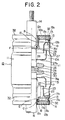
- a vacuum interrupter as such as shown in Fig. 2, was invented by Sakuma et al. Inventions concerning the vacuum interrupter were applied for patent on June 26, 1981 (Publication No. 0043258). in the E.P.O. as application No.81302900.6 /
- the vacuum interrupter by Sakuma et al comprises a hollow metallic circular cylinder and a pair of circular insulating end plates provided at both the ends of the cylinder.
- the vacuum interrupter 10 in accordance with one preferred embodiment of the present invention is improved one of the vacuum interrupter invented by Sakuma'et al.
- a vacuum / 10A of the vacuum interrupter 10 is defined by the following members of the vacuum interrupter.
- the members of the vacuum interrupter comprise a hollow metallic circular cylinder 11, two insulating end plates 12a and 12b which are provided respectively near both the ends of the metallic cylinder 11, first auxiliary sealing members 13 in the form of a hollow metallic circular cylinder which are interposed between the metallic cylinder 11 and insulating end plates 12a and 12b so as to connect the members in vacuum-tightness, a stationary electric lead rod 14, the second auxiliary sealing member 15 in the form of a hollow metallic circular cylinder which serves to connect the stationary lead rod 14 to the insulating end plate 12a in vacuum-tightness, a movable electric lead rod 16 which is movable to and from the stationary lead rod 14 along the axis thereof, bellows 17 which is mounted on the movable lead rod 16 within the metallic cylinder 11, the third auxiliary sealing member 18 in the form of a metallic ring which serves to connect an outside end of the bellows 17 to the insulating end plate 12b in vacuum-tightness, and the fourth auxiliary sealing member 19 in the form of a metallic ring
- the metallic cylinder 11 is made of stainless steel.
- Both of the insulating end plates 12a and 12b which are made of unglazed insulating ceramics, for example, unglazed alumina ceramics are disc-shaped.
- the outer diameter of the disc shape is substantially identical to those of both the ends of the metallic cylinder 11.
- the insulating end plates 12a and 12b are respectively provided at their centers with apertures 12c through which the stationary lead rod 14 and the movable lead rod 16 extend into the metallic cylinder 11, respectively.
- the vacuum-room-side surface of the insulating end plate 12b is provided, around the aperture 12c and on the outer periphery of the insulating end plate 12b with annular central and outer peripheral shoulders 20 and 21, respectively.
- the annular central and outer peripheral shoulders 20 and 21 are respectively provided with metallized layers 20a and 21a for the purpose of facilitating a vacuum-tight brazing.
- a circularly annular barrier 22 which is projecting in the vacuum room 10A more than both of the central and outer peripheral shoulders 20 and 21, is formed between the central and outer peripheral shoulders 20 and 21.
- the first auxiliary sealing member 13 made of Fe-Co-Ni or Fe-Ni alloy or of copper is employed in order to improve reliability of a vacuum-tight sealing between the metallic cylinder 11 and the insulating end plates 12a and 12b by eliminating, in a plastic deformation of the member 13, thermal stress which is to be caused during a slow cooling process after the vacuum-tight brazing in the vacuum furnace due to different coefficients of thermal expansion between the metallic cylinder 11 and the insulating end plates 12a and 12b.
- the auxiliary sealing member made of Fe-Ni-Co or Fe-Ni alloy is usually used because thermal expansion coefficient of each alloy is nearly same as that of the insulating end plate made of ceramics.
- the material of the first auxiliary sealing member 13 is preferably copper because copper is inexpensive, relatively large in mechanical strength, and anticorrosive.
- the first auxiliary sealing member 13 is provided at its one end with the first outwardly extending flange 13a which is brazed to the outer peripheral metallized layer 21a of the insulating end plate 12a or 12b,. and in the vicinity of the other end with the second outwardly extending flange 13b which is brazed to the annular end surface of the metallic cylinder 11.
- the first auxiliary sealing member 13 is also provided, between the positions of the first and second outwardly extending flanges 13a and 13b, with an inwardly extending flange 13c supporting an auxiliary shield 23.
- the stationary lead rod 14 which is a stepped shaft made of copper or a copper alloy comprises the inside chamber end portion located in the vacuum ⁇ 10A, and the outside end extending outwardly of the metallic cylinder 11 through the aperture 12c of the insulating end plate 12a.
- a stationary disc-shaped electrode 25 having a stationary contact. 24 is rigidly mounted on a periphery of the inside end of the stationary lead rod 14.
- a bottom 27a of an arc shield 27 in the form of a bottomed cylinder is rigidly secured to a periphery of a portion near to the inside end portion of the stationary lead rod 14, being mounted on a shoulder 26 of the stationary lead rod 14.
- An inwardly extending flange 15a which is formed at the inside end of the second auxiliary sealing member 15 made of copper is brazed to a periphery of a substantially middle portion of the stationary lead rod 14 via a snap ring 28.
- the annular end surface of the second auxiliary sealing member 15 is brazed to the central metallized layer 20a of the insulating end plate 12a.
- the second auxiliary sealing member 15 made of copper is employed because the stationary lead rod 14 has a shape difficult to be plastically deformed during the slow cooling process after the vacuum-tight brazing, functioning as the first auxiliary sealing member 13.
- The.movable lead rod 16 which is made of copper or a copper alloy as the stationary lead rod 14, comprises the inside end portion located in the vacuum room 10A, and the outside end extending outwardly of the metallic cylinder 11 through the aperture 12c of the insulating end plate 12b.
- a movable disc-shaped electrode 30 which has a movable contact 29 and the shape substantially identical to that of the stationary electrode 25 is rigidly mounted ' on the inside end portion of the movable lead rod 16.
- a bottom 31a of a bellows shield 31 in the form of a bottomed cylinder is rigidly secured to a periphery of the inside end portion of the movable lead rod 16 via the fourth auxiliary sealing member 19 which is rigidly secured to a periphery of a near portion to the inside end portion of the movable lead rod 16.
- the bellows shield 31 has the same shape to that of the arc shield and is made of the same material to that thereof.
- the bellows 17, made of stainless steel, is provided at the outside end with a brazing cylindrical portion 17a.
- the third auxiliary sealing member 18 made of copper is interposed between the brazing cylindrical portion 17 a and the central shoulder 20 of the insulating end plate 12b via the metallized layer 20a. Since the bellows 17 has a thickness of about 0.1 mm, it is negligible for the bellows 17 to have a coefficient of thermal expansiop different from the insulating end plate 12b.
- the brazing cylindrical portion 17a of the bellows 17, therefore, may be directly brazed to the metallized layer 20a.
- the third auxiliary sealing member 18 which during the slow cooling process after the vacuum-tight brazing functions like the first auxiliary sealing member 13, which can secure a high durable and reliable vacuum-tightness between the insulating end plate 12b and the brazing cylindrical portion 17a of the bellows 17.
- the fourth auxiliary sealing member 19 is employed to braze the bellows 17 and the movable lead rod 16 to one another and to support the bellows shield 31, all of which are metals.
- the fourth auxiliary sealing member 19 must not function like the first auxiliary sealing member 13 during the slow cooling process after the vacuum-tight brazing.
- An impervious insulating film 32 is generally formed to cover each atmospheric-side surface of the insulating end plates 12a and 12b, of the brazed portions and vicinities thereof A between each insulating end plate 12a or 12b, and the first outwardly extending flanges 13a of the first auxiliary sealing members 13, of the brazed portion and vicinity thereof B between the insulating end plate 12a and the second auxiliary sealing member 15, and of the brazed portion and vicinity thereof C between the insulating end plate 12b and the third auxiliary sealing member 18.
- the- insulating film 32 is generally formed to cover each atmospheric-side surface of the brazed portions and vicinities thereof D between the second outwardly extending flanges 13b of the first auxiliary sealing members 13 and the metallic cylinder 11, of the brazed portion and vicinity thereof E between the brazing cylindrical portion 17a of the bellows 17 and the third auxiliary sealing member 18, and of the brazed portion and vicinity thereof F between the stationary lead rod 14 and the second auxiliary sealing member 15.
- the insulating film 32 is strongly adhesive to any of surfaces of the insulating end plates 12a and 12b made of unglazed insulating ceramics, of surfaces of the first, second and third metallic auxiliary sealing members 13, 15 and 18 made of copper, of the surfaces of the vicinities of the brazed portions of the metallic cylinder 11, of the surface of the vicinity of the brazed portion of the metallic bellows 17, of the periphery of the vicinity of the brazed portion of the stationary lead rod 14, and of the atmospheric-side surfaces of the solidified brazing metal.
- the insulating film 32 which is made from insulating paint and/or varnish is obtainable by applying the insulating paint and/or varnish coated on each predetermined portion of the vacuum interrupter 10 which is taken out of the vacuum furnace after the vacuum brazing, in a clean state of surfaces of the metallic and ceramic members of the vacuum interrupter 10, and then by drying the applied insulating paint and/or varnish spontaneously or by heating.
- the clean surfaces of the metallic and ceramic members of the vacuum interrupter 10 much improve adhesive strength of the insulating film 32 to them.
- An insulating resin paint such as an insulating ulethan or epoxy resin family paint may preferably be employed as insulating paint.
- the insulating film 32 made from the paint has specially excellent weatherproofness.
- an insulating film made from insulating varnish has greater adhesive strength, larger suppression to generate pin holes, and greater abrasion resistance than an insulating film made from insulating paint.
- the insulating film 32 which is made from an electrically insulating finish varnish of a.
- the insulating film 32 may comprise two layers of an undercoating film made from insulating varnish and an overcoating film from insulating paint.
- the two-ply insulating film obtains advantages of both of the films from insulating varnish and paint.
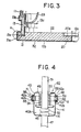
- a vacuum envelope of the vacuum interrupter 40 comprises a cup-shaped metallic housing 41, a short and circular insulating cylinder 42 which is made of unglazed insulating ceramics, and a metallic cap 43 in the form of a shallow dish.
- the metallic housing 41 is provided at the open end with an outwardly extending flange 44, and at the inner surface of the bottom 45 with a stationary contact 46 which is rigidly secured to the inner surface of the bottom 45.
- the stationary contact 46 is electrically and mechanically connected to a stationary lead rod 47 extending outwardly of the metallic housing 41 through the bottom 45.
- the metallic cap 43 is provided at the open end with an outwardly extending flange 48 as the outwardly extending flange 44.
- the metallic cap 43 has also an aperture 50 at the center of a bottom 49 thereof.
- a movable lead rod 51 extends outwardly of the metallic cap 43 through the aperture 50.
- a movable contact 52 is rigidly secured to the inside end of the movable lead rod 51 and located in the vacuum room 40A of the vacuum interrupter 40.
- the aperture 50 of the metallic cap 43 is sealed in vacuum-tightness with metallic bellows 54 which is engaged between a boss 53 defining the aperture 50 and the movable leadrod 51.
- the insulating cylinder 42 is a short and circular thick walled cylinder which is made of the same material as the insulating end plates 12a and 12b. Annular end plates 42a and 42b of the insulating cylinder 42 are provided on the respective outer peripheries with annular metallized layers 55. The outwardly extending flanges 44 and 48 of the metallic housing 41 and of the metallic cap 43' are brazed directly to the metallized layers 55, respectively.
- An insulating film 56 is generally formed to cover each atmospheric-side surface of the insulating cylinder 42 made of unglazed ceramics including the outer periphery of the insulating cylinder 42 and the outer peripheries of both the end surfaces 42a and 42b of the insulating cylinder 42, of a brazed portion and vicinity thereof G between the metallic housing 41 and an annular end plate 42b of the insulating cylinder 42, and of a brazed portion and vicinity thereof H between the metallic cap 43 and the annular end plate 42a of the insulating cylinder 42.
- the insulating film 56 has the same structure and characteristics and is produced in the same manner as the insulating film 32 in accordance with the embodiment of Fig. 2.
- the present invention is applicable not only to the above-described embodiments, but also to a vacuum interrupter comprising a vacuum envelope which comprises an insulating cylinder and two metallic end plates, for example, as shown in Fig. 1. Also, it is applicable to a vacuum interrupter (not shown) comprising a vacuum envelope which comprises a metallic cylinder and two insulating ceramic end plates brazed directly to the respective end surfaces of the metallic cylinder. Further, it is applicable to a vacuum interrupter comprising a vacuum envelope which comprises a cup-shaped metallic housing and an insulating ceramic end plate brazed directly to the open end of the cup-shaped metallic housing (See European patent publication No. 0029691). Further, it is applicable to a vacuum interrupter (not shown) comprising a vacuum envelope which comprises a cup-shaped metallic housing and an insulating ceramic end plate joined via an auxiliary sealing member to the open end of the housing.
Landscapes
- High-Tension Arc-Extinguishing Switches Without Spraying Means (AREA)
Applications Claiming Priority (2)
| Application Number | Priority Date | Filing Date | Title |
|---|---|---|---|
| JP1981190180U JPS5894233U (ja) | 1981-12-19 | 1981-12-19 | 真空インタラプタ |
| JP190180/81U | 1981-12-19 |
Publications (2)
| Publication Number | Publication Date |
|---|---|
| EP0084238A1 true EP0084238A1 (fr) | 1983-07-27 |
| EP0084238B1 EP0084238B1 (fr) | 1986-05-28 |
Family
ID=16253773
Family Applications (1)
| Application Number | Title | Priority Date | Filing Date |
|---|---|---|---|
| EP82306701A Expired EP0084238B1 (fr) | 1981-12-19 | 1982-12-15 | Interrupteur à vide |
Country Status (5)
| Country | Link |
|---|---|
| US (1) | US4482790A (fr) |
| EP (1) | EP0084238B1 (fr) |
| JP (1) | JPS5894233U (fr) |
| KR (1) | KR860002081B1 (fr) |
| DE (1) | DE3271474D1 (fr) |
Cited By (4)
| Publication number | Priority date | Publication date | Assignee | Title |
|---|---|---|---|---|
| EP0187950A1 (fr) * | 1984-12-14 | 1986-07-23 | Siemens Aktiengesellschaft | Interrupteur à vide |
| EP0254089A1 (fr) * | 1986-07-11 | 1988-01-27 | Siemens Aktiengesellschaft | Tube interrupteur sous vide |
| WO1992006482A1 (fr) * | 1990-09-28 | 1992-04-16 | Siemens Aktiengesellschaft | Procede pour accroitre la rigidite dielectrique et pour ameliorer le comportement aux courants de fuite de bandes d'isolement et application de ce procede aux interrupteurs a vide |
| DE9401655U1 (de) * | 1993-06-18 | 1994-11-03 | Siemens AG, 80333 München | Vakuumschaltröhre mit ringförigem Isolator |
Families Citing this family (4)
| Publication number | Priority date | Publication date | Assignee | Title |
|---|---|---|---|---|
| DE3764402D1 (de) * | 1986-06-02 | 1990-09-27 | Siemens Ag | Verfahren und anordnung zur nasszerlegung radioaktiv kontaminierter oder aktivierter komponenten von kernreaktoranlagen. |
| JP4031895B2 (ja) * | 2000-02-09 | 2008-01-09 | 日本特殊陶業株式会社 | 釉薬層付きセラミック部材を用いた金属−セラミック接合体及びそれを用いた真空スイッチユニット |
| DE102006041149B4 (de) * | 2006-09-01 | 2008-09-04 | Abb Technology Ag | Vakuumschaltkammer für Mittelspannungsschaltanlagen |
| DE102017222413A1 (de) * | 2017-12-11 | 2019-06-13 | Siemens Aktiengesellschaft | Überdruckfeste Vakuumschaltröhre |
Citations (3)
| Publication number | Priority date | Publication date | Assignee | Title |
|---|---|---|---|---|
| FR1428285A (fr) * | 1964-03-06 | 1966-02-11 | Ass Elect Ind | Perfectionnements aux interrupteurs dans le vide |
| GB2029643A (en) * | 1978-08-24 | 1980-03-19 | Tokyo Shibaura Electric Co | Vacuum circuit breakers |
| GB2038559A (en) * | 1978-12-06 | 1980-07-23 | Tokyo Shibaura Electric Co | Vacuum switch |
Family Cites Families (5)
| Publication number | Priority date | Publication date | Assignee | Title |
|---|---|---|---|---|
| US3674958A (en) * | 1970-11-23 | 1972-07-04 | Allis Chalmers Mfg Co | Vacuum circuit interrupter |
| JPS5279279A (en) * | 1975-12-25 | 1977-07-04 | Mitsubishi Electric Corp | Vacuum valve circuit breaker |
| DD147023A1 (de) * | 1979-11-01 | 1981-03-11 | Wolfgang Kuehn | Halterung des gleitlagers in einer vakuumschaltkammer |
| JPS5676131A (en) * | 1979-11-26 | 1981-06-23 | Meidensha Electric Mfg Co Ltd | Vacuum breaker |
| US4408107A (en) * | 1981-06-24 | 1983-10-04 | Kabushiki Kaisha Meidensha | Vacuum interrupter |
-
1981
- 1981-12-19 JP JP1981190180U patent/JPS5894233U/ja active Granted
-
1982
- 1982-12-10 US US06/448,460 patent/US4482790A/en not_active Expired - Lifetime
- 1982-12-15 EP EP82306701A patent/EP0084238B1/fr not_active Expired
- 1982-12-15 DE DE8282306701T patent/DE3271474D1/de not_active Expired
- 1982-12-17 KR KR828205673A patent/KR860002081B1/ko not_active Expired
Patent Citations (3)
| Publication number | Priority date | Publication date | Assignee | Title |
|---|---|---|---|---|
| FR1428285A (fr) * | 1964-03-06 | 1966-02-11 | Ass Elect Ind | Perfectionnements aux interrupteurs dans le vide |
| GB2029643A (en) * | 1978-08-24 | 1980-03-19 | Tokyo Shibaura Electric Co | Vacuum circuit breakers |
| GB2038559A (en) * | 1978-12-06 | 1980-07-23 | Tokyo Shibaura Electric Co | Vacuum switch |
Cited By (4)
| Publication number | Priority date | Publication date | Assignee | Title |
|---|---|---|---|---|
| EP0187950A1 (fr) * | 1984-12-14 | 1986-07-23 | Siemens Aktiengesellschaft | Interrupteur à vide |
| EP0254089A1 (fr) * | 1986-07-11 | 1988-01-27 | Siemens Aktiengesellschaft | Tube interrupteur sous vide |
| WO1992006482A1 (fr) * | 1990-09-28 | 1992-04-16 | Siemens Aktiengesellschaft | Procede pour accroitre la rigidite dielectrique et pour ameliorer le comportement aux courants de fuite de bandes d'isolement et application de ce procede aux interrupteurs a vide |
| DE9401655U1 (de) * | 1993-06-18 | 1994-11-03 | Siemens AG, 80333 München | Vakuumschaltröhre mit ringförigem Isolator |
Also Published As
| Publication number | Publication date |
|---|---|
| EP0084238B1 (fr) | 1986-05-28 |
| US4482790A (en) | 1984-11-13 |
| JPS5894233U (ja) | 1983-06-25 |
| DE3271474D1 (en) | 1986-07-03 |
| KR860002081B1 (ko) | 1986-11-24 |
| JPS6334195Y2 (fr) | 1988-09-12 |
| KR840003138A (ko) | 1984-08-13 |
Similar Documents
| Publication | Publication Date | Title |
|---|---|---|
| SU938756A3 (ru) | Способ изготовлени вакуумного выключател | |
| AU613004B2 (en) | Subminiature fuse | |
| US4482790A (en) | Vacuum interrupter | |
| EP0087881B1 (fr) | Procédé de liaison de cuivre ou alliage de cuivre-chrome avec des céramiques et produits liés en céramique et cuivre ou alliage de cuivre-chrome | |
| EP0129080B1 (fr) | Interrupteur sous vide | |
| US4582210A (en) | Casing for display device | |
| US4880947A (en) | Vacuum interrupter with simplified enclosure and method of assembly | |
| JPS6213778B2 (fr) | ||
| US2241505A (en) | Manufacture of metal to porcelain seals | |
| US3368023A (en) | Hermetically sealed envelope structure for vacuum component | |
| JP3361932B2 (ja) | 真空バルブ | |
| EP0051475B1 (fr) | Interrupteur à vide | |
| US4795866A (en) | Vacuum tube switch which uses low temperature solder | |
| EP0050955B1 (fr) | Interrupteur à vide | |
| EP0043258B1 (fr) | Interrupteur à vide et méthodes pour sa fabrication | |
| US4499349A (en) | Vacuum interrupter | |
| US3668350A (en) | Vacuum type circuit interrupter | |
| US4860437A (en) | Method of making a sub-miniature fuse | |
| JPS5942925B2 (ja) | 真空バルブ | |
| KR870000722B1 (ko) | 세라믹스와 동재 또는 동-크롬합금재와의 접합 방법 | |
| US3857005A (en) | Vacuum switch assembly | |
| JPH0113620B2 (fr) | ||
| US4310736A (en) | Vacuum circuit interrupter | |
| GB2182804A (en) | Casing of vacuum interrupters | |
| JP2009048842A (ja) | 真空スイッチおよびその製造方法 |
Legal Events
| Date | Code | Title | Description |
|---|---|---|---|
| PUAI | Public reference made under article 153(3) epc to a published international application that has entered the european phase |
Free format text: ORIGINAL CODE: 0009012 |
|
| AK | Designated contracting states |
Designated state(s): CH DE FR GB IT LI NL SE |
|
| 17P | Request for examination filed |
Effective date: 19840117 |
|
| GRAA | (expected) grant |
Free format text: ORIGINAL CODE: 0009210 |
|
| ITF | It: translation for a ep patent filed | ||
| AK | Designated contracting states |
Kind code of ref document: B1 Designated state(s): CH DE FR GB IT LI NL SE |
|
| ET | Fr: translation filed | ||
| REF | Corresponds to: |
Ref document number: 3271474 Country of ref document: DE Date of ref document: 19860703 |
|
| PLBI | Opposition filed |
Free format text: ORIGINAL CODE: 0009260 |
|
| 26 | Opposition filed |
Opponent name: VEB ELEKTRO-APPARATEWERKE BERLIN - TREPTOW Effective date: 19870302 |
|
| NLR1 | Nl: opposition has been filed with the epo |
Opponent name: VEB ELEKTRO-APPARATEWERKE BERLIN-TREPTOW |
|
| ITTA | It: last paid annual fee | ||
| PGFP | Annual fee paid to national office [announced via postgrant information from national office to epo] |
Ref country code: NL Payment date: 19891231 Year of fee payment: 8 |
|
| PGFP | Annual fee paid to national office [announced via postgrant information from national office to epo] |
Ref country code: SE Payment date: 19900117 Year of fee payment: 8 |
|
| PGFP | Annual fee paid to national office [announced via postgrant information from national office to epo] |
Ref country code: CH Payment date: 19900118 Year of fee payment: 8 |
|
| PGFP | Annual fee paid to national office [announced via postgrant information from national office to epo] |
Ref country code: FR Payment date: 19900123 Year of fee payment: 8 |
|
| PGFP | Annual fee paid to national office [announced via postgrant information from national office to epo] |
Ref country code: DE Payment date: 19900129 Year of fee payment: 8 |
|
| PGFP | Annual fee paid to national office [announced via postgrant information from national office to epo] |
Ref country code: GB Payment date: 19900131 Year of fee payment: 8 |
|
| RDAG | Patent revoked |
Free format text: ORIGINAL CODE: 0009271 |
|
| STAA | Information on the status of an ep patent application or granted ep patent |
Free format text: STATUS: PATENT REVOKED |
|
| 27W | Patent revoked |
Effective date: 19900312 |
|
| GBPR | Gb: patent revoked under art. 102 of the ep convention designating the uk as contracting state | ||
| REG | Reference to a national code |
Ref country code: CH Ref legal event code: PL |
|
| NLR2 | Nl: decision of opposition | ||
| EUG | Se: european patent has lapsed |
Ref document number: 82306701.2 Effective date: 19900808 |