EP0084257B1 - Anschlussanordnung und Anschlusselement für Flachkabel - Google Patents
Anschlussanordnung und Anschlusselement für Flachkabel Download PDFInfo
- Publication number
- EP0084257B1 EP0084257B1 EP82306931A EP82306931A EP0084257B1 EP 0084257 B1 EP0084257 B1 EP 0084257B1 EP 82306931 A EP82306931 A EP 82306931A EP 82306931 A EP82306931 A EP 82306931A EP 0084257 B1 EP0084257 B1 EP 0084257B1
- Authority
- EP
- European Patent Office
- Prior art keywords
- lance
- cable
- conductor
- mouth
- socket
- Prior art date
- Legal status (The legal status is an assumption and is not a legal conclusion. Google has not performed a legal analysis and makes no representation as to the accuracy of the status listed.)
- Expired
Links
- 239000004020 conductor Substances 0.000 title claims abstract description 43
- 239000002184 metal Substances 0.000 claims abstract description 22
- 239000000463 material Substances 0.000 claims abstract description 5
- 230000000149 penetrating effect Effects 0.000 claims abstract description 3
- 230000015572 biosynthetic process Effects 0.000 claims abstract 2
- 238000009413 insulation Methods 0.000 claims description 9
- 230000035515 penetration Effects 0.000 claims description 3
- 230000006835 compression Effects 0.000 description 2
- 238000007906 compression Methods 0.000 description 2
- 230000037431 insertion Effects 0.000 description 2
- 238000003780 insertion Methods 0.000 description 2
- 229920002799 BoPET Polymers 0.000 description 1
- 229910000881 Cu alloy Inorganic materials 0.000 description 1
- 239000005041 Mylar™ Substances 0.000 description 1
- 239000000853 adhesive Substances 0.000 description 1
- 230000001070 adhesive effect Effects 0.000 description 1
- 230000000694 effects Effects 0.000 description 1
- 230000002708 enhancing effect Effects 0.000 description 1
Images
Classifications
-
- H—ELECTRICITY
- H01—ELECTRIC ELEMENTS
- H01R—ELECTRICALLY-CONDUCTIVE CONNECTIONS; STRUCTURAL ASSOCIATIONS OF A PLURALITY OF MUTUALLY-INSULATED ELECTRICAL CONNECTING ELEMENTS; COUPLING DEVICES; CURRENT COLLECTORS
- H01R4/00—Electrically-conductive connections between two or more conductive members in direct contact, i.e. touching one another; Means for effecting or maintaining such contact; Electrically-conductive connections having two or more spaced connecting locations for conductors and using contact members penetrating insulation
- H01R4/24—Connections using contact members penetrating or cutting insulation or cable strands
- H01R4/2495—Insulation penetration combined with permanent deformation of the contact member, e.g. crimping
-
- H—ELECTRICITY
- H01—ELECTRIC ELEMENTS
- H01R—ELECTRICALLY-CONDUCTIVE CONNECTIONS; STRUCTURAL ASSOCIATIONS OF A PLURALITY OF MUTUALLY-INSULATED ELECTRICAL CONNECTING ELEMENTS; COUPLING DEVICES; CURRENT COLLECTORS
- H01R12/00—Structural associations of a plurality of mutually-insulated electrical connecting elements, specially adapted for printed circuits, e.g. printed circuit boards [PCB], flat or ribbon cables, or like generally planar structures, e.g. terminal strips, terminal blocks; Coupling devices specially adapted for printed circuits, flat or ribbon cables, or like generally planar structures; Terminals specially adapted for contact with, or insertion into, printed circuits, flat or ribbon cables, or like generally planar structures
- H01R12/50—Fixed connections
- H01R12/59—Fixed connections for flexible printed circuits, flat or ribbon cables or like structures
- H01R12/61—Fixed connections for flexible printed circuits, flat or ribbon cables or like structures connecting to flexible printed circuits, flat or ribbon cables or like structures
- H01R12/613—Fixed connections for flexible printed circuits, flat or ribbon cables or like structures connecting to flexible printed circuits, flat or ribbon cables or like structures by means of interconnecting elements
- H01R12/616—Fixed connections for flexible printed circuits, flat or ribbon cables or like structures connecting to flexible printed circuits, flat or ribbon cables or like structures by means of interconnecting elements having contacts penetrating insulation for making contact with conductors, e.g. needle points
-
- H—ELECTRICITY
- H01—ELECTRIC ELEMENTS
- H01R—ELECTRICALLY-CONDUCTIVE CONNECTIONS; STRUCTURAL ASSOCIATIONS OF A PLURALITY OF MUTUALLY-INSULATED ELECTRICAL CONNECTING ELEMENTS; COUPLING DEVICES; CURRENT COLLECTORS
- H01R12/00—Structural associations of a plurality of mutually-insulated electrical connecting elements, specially adapted for printed circuits, e.g. printed circuit boards [PCB], flat or ribbon cables, or like generally planar structures, e.g. terminal strips, terminal blocks; Coupling devices specially adapted for printed circuits, flat or ribbon cables, or like generally planar structures; Terminals specially adapted for contact with, or insertion into, printed circuits, flat or ribbon cables, or like generally planar structures
- H01R12/50—Fixed connections
- H01R12/59—Fixed connections for flexible printed circuits, flat or ribbon cables or like structures
-
- H—ELECTRICITY
- H01—ELECTRIC ELEMENTS
- H01R—ELECTRICALLY-CONDUCTIVE CONNECTIONS; STRUCTURAL ASSOCIATIONS OF A PLURALITY OF MUTUALLY-INSULATED ELECTRICAL CONNECTING ELEMENTS; COUPLING DEVICES; CURRENT COLLECTORS
- H01R2101/00—One pole
Definitions
- the invention relates to the termination of ribbon conductors and more particularly to the termination of flat cable having ribbon conductors sandwiched between layers of insulation.
- a terminal comprises a first metal plate portion from which upstands a cable penetrating tab-like lance having parallel opposite edge portions and a second metal plate portion provided with a socket aligned with the lance and having lips pushed out of the plane of the plate and converging towards their free ends to define a lance receiving mouth, the lance being proportioned to pass through the cable and into the mouth.
- a disadvantage of the prior terminal is that the force required to obtain a satisfactory electrical connection between the contact rings and the cable conductor is relatively high. Furthermore, as the lance-receiving mouth of the prior terminal is circular, there may be risk of relaxation of the connection in view of the small area of direct contact between the edge portions of the tab-like lance and the socket lip.
- the terminal can be applied with simple tooling and without need for a high force. It is further preferred that the resulting terminations will have a relatively high current carrying capacity.
- the lance receiving mouth is slot-form, the arrangement being such that, after penetration of the cable by the lance, a portion of the cable conductor will be drawn into the mouth by the lance compressed between and in direct contact with, a face of the lance and one lip by insertion of the lance into the socket.
- the conductor portion is compressed between two metal parts for a distance equal to the entire width of the tab ensuring a good electrical connection.
- Each interface of the connection is metal to metal resulting in a gas tight connection.
- the lance has been struck out from the first metal plate portion providing an aperture into which a portion of the cable is deformed during termination, the face of the lance engaged by the conductor portion being adjacent the aperture.
- an electrical connection between a ribbon conductor and first and second metal plate portions of an electrical terminal in which a tab-like lance having parallel opposite edge portions upstanding from the first metal plate portion and a free end penetrates the ribbon conductor and is received in a socket provided in the second plate portion, the socket having lips pushed out of the plane of the second plate portion and converging towards their free ends to define lance-receiving mouth, the lance passing through the cable and into the mouth, the lance-receiving mouth being slot-form and a portion of the conductor having been drawn into the mouth by the free end of the lance and compressed between and in direct contact with one lip and a face of the lance.
- ribbon conductor material has been displaced from between the face of the tab and the one lip further into the socket.
- a terminal for very thin foil-like conductors includes opposed metal plate portions each formed with raised teeth which engage the conductor where the plate portions are urged together.
- a disadvantage of the known connector is that all of the teeth must pierce and tear the conductor during termination to effect connection with the result that not only is a relatively high termination force required but the conductor is substantially weakened by the piercing and tearing. It would not be practicable to use the known connector to terminate flat cable in which the ribbon conductor is relatively thick in view of the high force required.
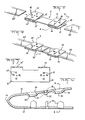
- the splice terminal 11 is stamped and formed from a single piece of sheet metal stock, (approximately 4 mm (.016 inches) thick Cu alloy 195), and comprises first and second plate portions 12, 12' and 13, 13' at respective opposite ends for terminating respective ends of flat cable 20, 20'.
- Each first plate portion 12 or 12' is integrally joined to its respective second plate portion 13 or 13' by an integral web 14 or 14'.
- a series of tab-form lances 15 and 15' having parallel opposite edge portions are located in cruciform fashion on respective first plate portions in alignment with a corresponding series of sockets 16 and 16' located on the respective second plate portions.
- Each lance 15 or 15' is pushed out of the plane of the plate portion providing an aperture 17 or 17'.
- Each socket 16 or 16' has lips 19 pushed out of the plane of the plate portion and converging towards their free ends to define a slot-form lance receiving mouth 21.
- the edges 22 of the lips 19 are relatively sharp being defined by piercing through impressed portions of the plate to provide the mouth.
- the flat cables comprise ribbon conductors 23 of 2.286 mm to 3.556 m (.009 to.014 inches) thick sandwiched between first and second layers of insulation 24 and 25 (Trade Mark: "Mylar”) approximately 1.778 mm (.007 inches) thick and a proprietary adhesive.
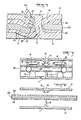
- a cable is inserted between first and second plate portions 12 and 13 and a plier type tool having planar pressing faces is used to apply a force of approximately 4488 N (1,000 pounds) to the plate portions forcing the lances through the cable into the mouths drawing with them portions 27 of the ribbon conductor.
- a portion 28 of the insulation is severed by the edge 22 of the lip 19 and ultimately expelled from between the conductor and lip.
- Conductor material is displaced from between the faces of the lances and the lips 19 leaving portions 26 of reduced thickness compressed between and in direct contact with the faces of the lances and the lips.
- Portions of ribbon conductor and the other layer 25 of insulation are deformed into the respective apertures 17. Forces acting on the free end 31 of the lance during termination broaden the free end assisting in preventing relaxation of the connection and are transmitted through the lance to the portion 26 of the conductor enhancing the compressive force.
- the resulting termination is capable of carrying relatively high currents of up to 60 amps and yet the termination is of relatively low height.
- the termination is particularly suitable for undercarpet flat cable.
Landscapes
- Coupling Device And Connection With Printed Circuit (AREA)
- Multi-Conductor Connections (AREA)
- Connections By Means Of Piercing Elements, Nuts, Or Screws (AREA)
- Insulated Conductors (AREA)
- Connections Effected By Soldering, Adhesion, Or Permanent Deformation (AREA)
Claims (9)
Priority Applications (1)
| Application Number | Priority Date | Filing Date | Title |
|---|---|---|---|
| AT82306931T ATE16333T1 (de) | 1982-01-15 | 1982-12-23 | Anschlussanordnung und anschlusselement fuer flachkabel. |
Applications Claiming Priority (2)
| Application Number | Priority Date | Filing Date | Title |
|---|---|---|---|
| US33955782A | 1982-01-15 | 1982-01-15 | |
| US339557 | 1989-04-17 |
Publications (3)
| Publication Number | Publication Date |
|---|---|
| EP0084257A2 EP0084257A2 (de) | 1983-07-27 |
| EP0084257A3 EP0084257A3 (en) | 1983-08-10 |
| EP0084257B1 true EP0084257B1 (de) | 1985-10-30 |
Family
ID=23329587
Family Applications (1)
| Application Number | Title | Priority Date | Filing Date |
|---|---|---|---|
| EP82306931A Expired EP0084257B1 (de) | 1982-01-15 | 1982-12-23 | Anschlussanordnung und Anschlusselement für Flachkabel |
Country Status (9)
| Country | Link |
|---|---|
| EP (1) | EP0084257B1 (de) |
| JP (1) | JPS58123676A (de) |
| AT (1) | ATE16333T1 (de) |
| BR (1) | BR8300064A (de) |
| CA (1) | CA1195397A (de) |
| DE (1) | DE3267197D1 (de) |
| ES (1) | ES269585Y (de) |
| IE (1) | IE53862B1 (de) |
| MX (1) | MX157446A (de) |
Families Citing this family (6)
| Publication number | Priority date | Publication date | Assignee | Title |
|---|---|---|---|---|
| JPS59217971A (ja) * | 1983-05-25 | 1984-12-08 | 松下電工株式会社 | フラツトケ−ブル用コネクタ |
| EP0342868B1 (de) * | 1988-05-13 | 1994-01-26 | The Whitaker Corporation | Elektrischer Anschluss für flaches Energiekabel |
| DE19812093C1 (de) * | 1998-03-19 | 1999-10-07 | Framatome Connectors Int | Crimpverbindung |
| JP4191128B2 (ja) * | 2004-11-16 | 2008-12-03 | 古河電気工業株式会社 | フラットケーブルと電子部品との接続構造 |
| WO2018055777A1 (ja) * | 2016-09-26 | 2018-03-29 | 有限会社コスモポリタン | コネクタ |
| JP7232073B2 (ja) * | 2019-02-18 | 2023-03-02 | 日本航空電子工業株式会社 | 接続方法、接続構造および接続端子 |
Family Cites Families (6)
| Publication number | Priority date | Publication date | Assignee | Title |
|---|---|---|---|---|
| US3553347A (en) * | 1967-07-25 | 1971-01-05 | Post Office | Wire connectors |
| US3504101A (en) * | 1968-09-30 | 1970-03-31 | Amp Inc | Electric connector for aluminum foil |
| US3594704A (en) * | 1969-10-02 | 1971-07-20 | Raychem Corp | In-line connector for electrical conductors or the like |
| GB1396000A (en) * | 1972-11-29 | 1975-05-29 | Amp Inc | Electrical contacts for flat flexible cable |
| US3997233A (en) * | 1976-02-19 | 1976-12-14 | E. I. Du Pont De Nemours And Company | Flat conductor cable connector |
| US4558915A (en) * | 1980-02-21 | 1985-12-17 | Thomas & Betts Corporation | Electrical connector |
-
1982
- 1982-12-21 CA CA000418190A patent/CA1195397A/en not_active Expired
- 1982-12-23 AT AT82306931T patent/ATE16333T1/de not_active IP Right Cessation
- 1982-12-23 EP EP82306931A patent/EP0084257B1/de not_active Expired
- 1982-12-23 DE DE8282306931T patent/DE3267197D1/de not_active Expired
-
1983
- 1983-01-04 IE IE13/83A patent/IE53862B1/en unknown
- 1983-01-05 ES ES1983269585U patent/ES269585Y/es not_active Expired
- 1983-01-07 BR BR8300064A patent/BR8300064A/pt not_active IP Right Cessation
- 1983-01-14 JP JP58005176A patent/JPS58123676A/ja active Pending
- 1983-01-14 MX MX195913A patent/MX157446A/es unknown
Also Published As
| Publication number | Publication date |
|---|---|
| ES269585Y (es) | 1985-01-01 |
| JPS58123676A (ja) | 1983-07-22 |
| MX157446A (es) | 1988-11-23 |
| EP0084257A2 (de) | 1983-07-27 |
| ATE16333T1 (de) | 1985-11-15 |
| ES269585U (es) | 1983-11-01 |
| IE53862B1 (en) | 1989-03-29 |
| IE830013L (en) | 1983-07-15 |
| EP0084257A3 (en) | 1983-08-10 |
| CA1195397A (en) | 1985-10-15 |
| BR8300064A (pt) | 1983-09-20 |
| DE3267197D1 (en) | 1985-12-05 |
Similar Documents
| Publication | Publication Date | Title |
|---|---|---|
| US4560224A (en) | Flat cable termination | |
| EP0020031B1 (de) | Elektrischer Flachkabelverbinder | |
| EP0034000B1 (de) | Anschlussklemme für Schaltplatten | |
| US4859205A (en) | Strain relief for flat cable termination | |
| US4669798A (en) | Electrical terminal for flexible printed circuits | |
| US6232555B1 (en) | Crimp connection | |
| CA1068364A (en) | Flat conductor cable connector | |
| GB1474249A (en) | Electrical contact for flat conductor cable | |
| JPS6059709B2 (ja) | 平形ケ−ブル用電気コネクタ− | |
| EP0063457A1 (de) | Elektrischer Kontakt und Zusammenbau eines elektrischen Verbinders | |
| US4558915A (en) | Electrical connector | |
| JPH05275129A (ja) | ケーブルクランプ装置 | |
| EP0782215A1 (de) | Leiteranschlusselement und Verfahren zur Herstellung | |
| US4859204A (en) | Method of staking a wave crimp for flat power cable termination | |
| US4312556A (en) | Electrical connector | |
| US4867700A (en) | Wave crimp for flat power cable termination | |
| US6439921B1 (en) | Terminal fitting for flat conductor and method of connecting terminal fitting to flat conductor | |
| EP0084257A2 (de) | Anschlussanordnung und Anschlusselement für Flachkabel | |
| JPH05198320A (ja) | 楔形コネクタ | |
| EP0057579A2 (de) | Elektrische Steckverbinder | |
| EP0342868B1 (de) | Elektrischer Anschluss für flaches Energiekabel | |
| US4288918A (en) | Method and apparatus for making a crimped, insulation-pierce electrical connection | |
| US4725247A (en) | Cable splicing assembly | |
| US12597763B2 (en) | Compression connectors and protective covers | |
| US4950180A (en) | Electrical termination and method of terminating flat power cable |
Legal Events
| Date | Code | Title | Description |
|---|---|---|---|
| PUAI | Public reference made under article 153(3) epc to a published international application that has entered the european phase |
Free format text: ORIGINAL CODE: 0009012 |
|
| PUAL | Search report despatched |
Free format text: ORIGINAL CODE: 0009013 |
|
| AK | Designated contracting states |
Designated state(s): AT BE CH DE FR GB IT LI NL SE |
|
| AK | Designated contracting states |
Designated state(s): AT BE CH DE FR GB IT LI NL SE |
|
| 17P | Request for examination filed |
Effective date: 19840203 |
|
| ITF | It: translation for a ep patent filed | ||
| GRAA | (expected) grant |
Free format text: ORIGINAL CODE: 0009210 |
|
| AK | Designated contracting states |
Designated state(s): AT BE CH DE FR GB IT LI NL SE |
|
| REF | Corresponds to: |
Ref document number: 16333 Country of ref document: AT Date of ref document: 19851115 Kind code of ref document: T |
|
| REF | Corresponds to: |
Ref document number: 3267197 Country of ref document: DE Date of ref document: 19851205 |
|
| ET | Fr: translation filed | ||
| PLBE | No opposition filed within time limit |
Free format text: ORIGINAL CODE: 0009261 |
|
| STAA | Information on the status of an ep patent application or granted ep patent |
Free format text: STATUS: NO OPPOSITION FILED WITHIN TIME LIMIT |
|
| 26N | No opposition filed | ||
| ITTA | It: last paid annual fee | ||
| REG | Reference to a national code |
Ref country code: GB Ref legal event code: 732E |
|
| EAL | Se: european patent in force in sweden |
Ref document number: 82306931.5 |
|
| PGFP | Annual fee paid to national office [announced via postgrant information from national office to epo] |
Ref country code: NL Payment date: 19951004 Year of fee payment: 14 |
|
| PGFP | Annual fee paid to national office [announced via postgrant information from national office to epo] |
Ref country code: SE Payment date: 19951120 Year of fee payment: 14 |
|
| PGFP | Annual fee paid to national office [announced via postgrant information from national office to epo] |
Ref country code: AT Payment date: 19951123 Year of fee payment: 14 |
|
| PGFP | Annual fee paid to national office [announced via postgrant information from national office to epo] |
Ref country code: DE Payment date: 19951227 Year of fee payment: 14 |
|
| PGFP | Annual fee paid to national office [announced via postgrant information from national office to epo] |
Ref country code: CH Payment date: 19951229 Year of fee payment: 14 |
|
| PGFP | Annual fee paid to national office [announced via postgrant information from national office to epo] |
Ref country code: BE Payment date: 19960109 Year of fee payment: 14 |
|
| PG25 | Lapsed in a contracting state [announced via postgrant information from national office to epo] |
Ref country code: AT Effective date: 19961223 |
|
| PG25 | Lapsed in a contracting state [announced via postgrant information from national office to epo] |
Ref country code: SE Effective date: 19961224 |
|
| PG25 | Lapsed in a contracting state [announced via postgrant information from national office to epo] |
Ref country code: LI Effective date: 19961231 Ref country code: CH Effective date: 19961231 Ref country code: BE Effective date: 19961231 |
|
| BERE | Be: lapsed |
Owner name: AMP INC. (UNE SOC. DE PENNSYLVANIE) Effective date: 19961231 |
|
| PG25 | Lapsed in a contracting state [announced via postgrant information from national office to epo] |
Ref country code: NL Effective date: 19970701 |
|
| REG | Reference to a national code |
Ref country code: CH Ref legal event code: PL |
|
| NLV4 | Nl: lapsed or anulled due to non-payment of the annual fee |
Effective date: 19970701 |
|
| PG25 | Lapsed in a contracting state [announced via postgrant information from national office to epo] |
Ref country code: DE Effective date: 19970902 |
|
| EUG | Se: european patent has lapsed |
Ref document number: 82306931.5 |
|
| PGFP | Annual fee paid to national office [announced via postgrant information from national office to epo] |
Ref country code: GB Payment date: 20001107 Year of fee payment: 19 |
|
| PGFP | Annual fee paid to national office [announced via postgrant information from national office to epo] |
Ref country code: FR Payment date: 20001204 Year of fee payment: 19 |
|
| PG25 | Lapsed in a contracting state [announced via postgrant information from national office to epo] |
Ref country code: GB Free format text: LAPSE BECAUSE OF NON-PAYMENT OF DUE FEES Effective date: 20011223 |
|
| REG | Reference to a national code |
Ref country code: GB Ref legal event code: IF02 |
|
| GBPC | Gb: european patent ceased through non-payment of renewal fee |
Effective date: 20011223 |
|
| PG25 | Lapsed in a contracting state [announced via postgrant information from national office to epo] |
Ref country code: FR Free format text: LAPSE BECAUSE OF NON-PAYMENT OF DUE FEES Effective date: 20020830 |
|
| REG | Reference to a national code |
Ref country code: FR Ref legal event code: ST |