EP0084274B1 - Verfahren zur Herstellung von Polymeren mit sehr hohem Elastizitätsmodul - Google Patents
Verfahren zur Herstellung von Polymeren mit sehr hohem Elastizitätsmodul Download PDFInfo
- Publication number
- EP0084274B1 EP0084274B1 EP82307041A EP82307041A EP0084274B1 EP 0084274 B1 EP0084274 B1 EP 0084274B1 EP 82307041 A EP82307041 A EP 82307041A EP 82307041 A EP82307041 A EP 82307041A EP 0084274 B1 EP0084274 B1 EP 0084274B1
- Authority
- EP
- European Patent Office
- Prior art keywords
- speed
- take
- tube
- furnace
- dielectric heating
- Prior art date
- Legal status (The legal status is an assumption and is not a legal conclusion. Google has not performed a legal analysis and makes no representation as to the accuracy of the status listed.)
- Expired
Links
Images


Classifications
-
- H—ELECTRICITY
- H05—ELECTRIC TECHNIQUES NOT OTHERWISE PROVIDED FOR
- H05B—ELECTRIC HEATING; ELECTRIC LIGHT SOURCES NOT OTHERWISE PROVIDED FOR; CIRCUIT ARRANGEMENTS FOR ELECTRIC LIGHT SOURCES, IN GENERAL
- H05B6/00—Heating by electric, magnetic or electromagnetic fields
- H05B6/64—Heating using microwaves
- H05B6/78—Arrangements for continuous movement of material
- H05B6/788—Arrangements for continuous movement of material wherein an elongated material is moved by applying a mechanical tension to it
-
- B—PERFORMING OPERATIONS; TRANSPORTING
- B29—WORKING OF PLASTICS; WORKING OF SUBSTANCES IN A PLASTIC STATE IN GENERAL
- B29C—SHAPING OR JOINING OF PLASTICS; SHAPING OF MATERIAL IN A PLASTIC STATE, NOT OTHERWISE PROVIDED FOR; AFTER-TREATMENT OF THE SHAPED PRODUCTS, e.g. REPAIRING
- B29C35/00—Heating, cooling or curing, e.g. crosslinking or vulcanising; Apparatus therefor
- B29C35/02—Heating or curing, e.g. crosslinking or vulcanizing during moulding, e.g. in a mould
- B29C35/12—Dielectric heating
-
- B—PERFORMING OPERATIONS; TRANSPORTING
- B29—WORKING OF PLASTICS; WORKING OF SUBSTANCES IN A PLASTIC STATE IN GENERAL
- B29C—SHAPING OR JOINING OF PLASTICS; SHAPING OF MATERIAL IN A PLASTIC STATE, NOT OTHERWISE PROVIDED FOR; AFTER-TREATMENT OF THE SHAPED PRODUCTS, e.g. REPAIRING
- B29C55/00—Shaping by stretching, e.g. drawing through a die; Apparatus therefor
- B29C55/02—Shaping by stretching, e.g. drawing through a die; Apparatus therefor of plates or sheets
- B29C55/04—Shaping by stretching, e.g. drawing through a die; Apparatus therefor of plates or sheets uniaxial, e.g. oblique
- B29C55/06—Shaping by stretching, e.g. drawing through a die; Apparatus therefor of plates or sheets uniaxial, e.g. oblique parallel with the direction of feed
-
- B—PERFORMING OPERATIONS; TRANSPORTING
- B29—WORKING OF PLASTICS; WORKING OF SUBSTANCES IN A PLASTIC STATE IN GENERAL
- B29C—SHAPING OR JOINING OF PLASTICS; SHAPING OF MATERIAL IN A PLASTIC STATE, NOT OTHERWISE PROVIDED FOR; AFTER-TREATMENT OF THE SHAPED PRODUCTS, e.g. REPAIRING
- B29C55/00—Shaping by stretching, e.g. drawing through a die; Apparatus therefor
- B29C55/22—Shaping by stretching, e.g. drawing through a die; Apparatus therefor of tubes
-
- B—PERFORMING OPERATIONS; TRANSPORTING
- B29—WORKING OF PLASTICS; WORKING OF SUBSTANCES IN A PLASTIC STATE IN GENERAL
- B29C—SHAPING OR JOINING OF PLASTICS; SHAPING OF MATERIAL IN A PLASTIC STATE, NOT OTHERWISE PROVIDED FOR; AFTER-TREATMENT OF THE SHAPED PRODUCTS, e.g. REPAIRING
- B29C71/00—After-treatment of articles without altering their shape; Apparatus therefor
- B29C71/02—Thermal after-treatment
-
- B—PERFORMING OPERATIONS; TRANSPORTING
- B29—WORKING OF PLASTICS; WORKING OF SUBSTANCES IN A PLASTIC STATE IN GENERAL
- B29K—INDEXING SCHEME ASSOCIATED WITH SUBCLASSES B29B, B29C OR B29D, RELATING TO MOULDING MATERIALS OR TO MATERIALS FOR MOULDS, REINFORCEMENTS, FILLERS OR PREFORMED PARTS, e.g. INSERTS
- B29K2059/00—Use of polyacetals, e.g. POM, i.e. polyoxymethylene or derivatives thereof, as moulding material
-
- B—PERFORMING OPERATIONS; TRANSPORTING
- B29—WORKING OF PLASTICS; WORKING OF SUBSTANCES IN A PLASTIC STATE IN GENERAL
- B29K—INDEXING SCHEME ASSOCIATED WITH SUBCLASSES B29B, B29C OR B29D, RELATING TO MOULDING MATERIALS OR TO MATERIALS FOR MOULDS, REINFORCEMENTS, FILLERS OR PREFORMED PARTS, e.g. INSERTS
- B29K2061/00—Use of condensation polymers of aldehydes or ketones or derivatives thereof, as moulding material
-
- B—PERFORMING OPERATIONS; TRANSPORTING
- B29—WORKING OF PLASTICS; WORKING OF SUBSTANCES IN A PLASTIC STATE IN GENERAL
- B29K—INDEXING SCHEME ASSOCIATED WITH SUBCLASSES B29B, B29C OR B29D, RELATING TO MOULDING MATERIALS OR TO MATERIALS FOR MOULDS, REINFORCEMENTS, FILLERS OR PREFORMED PARTS, e.g. INSERTS
- B29K2105/00—Condition, form or state of moulded material or of the material to be shaped
- B29K2105/25—Solid
-
- B—PERFORMING OPERATIONS; TRANSPORTING
- B29—WORKING OF PLASTICS; WORKING OF SUBSTANCES IN A PLASTIC STATE IN GENERAL
- B29K—INDEXING SCHEME ASSOCIATED WITH SUBCLASSES B29B, B29C OR B29D, RELATING TO MOULDING MATERIALS OR TO MATERIALS FOR MOULDS, REINFORCEMENTS, FILLERS OR PREFORMED PARTS, e.g. INSERTS
- B29K2995/00—Properties of moulding materials, reinforcements, fillers, preformed parts or moulds
- B29K2995/0037—Other properties
- B29K2995/0041—Crystalline
-
- B—PERFORMING OPERATIONS; TRANSPORTING
- B29—WORKING OF PLASTICS; WORKING OF SUBSTANCES IN A PLASTIC STATE IN GENERAL
- B29K—INDEXING SCHEME ASSOCIATED WITH SUBCLASSES B29B, B29C OR B29D, RELATING TO MOULDING MATERIALS OR TO MATERIALS FOR MOULDS, REINFORCEMENTS, FILLERS OR PREFORMED PARTS, e.g. INSERTS
- B29K2995/00—Properties of moulding materials, reinforcements, fillers, preformed parts or moulds
- B29K2995/0037—Other properties
- B29K2995/0083—Creep
Definitions
- This invention relates to a continuous process for the production of polyoxymethylene (POM) rod or tube having a high tensile modulus and small linear expansion.
- POM polyoxymethylene
- Hot drawing processes have hitherfore been known in the art, including a process wherein a material is allowed to contact with a hot pin or hot-shoe, a process wherein a material is passed through a hot tube, a process wherein a material is allowed to contact with a rotating hot roller, and a process wherein a hot pin and a hot-shoe are used in combination.
- these known processes have a common disadvantage that these processes can be applied only to process a material in the form of a fiber having a diameter of less than about 0.1 mm or in the form of a film having a thickness of less than about 0.1 mm, since the material is heated from the outside in any of these known processes leading to the result that the inside of the material cannot be heated sufficiently uniformly when the material is processed in the form of a thicker fiber or film.
- the tensile modulus (Young's modulus) of a product polyester fiber processed through any of these known processes is in the order of 20 GPa (Giga Pascals) at the highest.
- United States Patent No: 3364294 discloses a process according to the first portion of claim 1 in which a polyester tow is continuously drawn out to a multiple of its original length at an elevated and constant temperature below its melting-point while held within a furnace and supplied with microwave energy and with radiant heating.
- the description and claims of that patent relate only to polyethylene terephthalate in the form of a tow, and the apparatus described could not be used for the drawing of rod or tube.
- the problem towards which that patent is directed is that of obtaining uniform heating of the constituent fibres of the tow so as to obtain uniform results from the draining and any subsequent dyeing steps, a problem which does not arise with the present invention.
- An object of the present invention is to provide polyoxymethylene rod or tube of high tensile modulus.
- the present invention provides a process for the production of polymeric material of high tensile strength and reduced coefficient of thermal expansion, in which the polymeric material is continuously drawn out to a multiple of its original length at an elevated temperature below its melting point while heated within a furnace and supplied with microwave energy and with radiant heating, and is characterised in that:
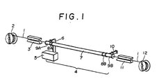
- Fig. 1 shows an embodiment of an arrangement in which a POM (polyoxymethylene) rod or tube 1 is processed through the process of this invention.
- the arrangement comprises a feed reel 2, a belt caterpillar type feeder 3, an apparatus 4 in which the POM rod or tube 1 is subjected to dielectric heating according to the process of this invention, a belt caterpillar type take-up machine 11, and a take-up reel 12.
- the apparatus 4 for effecting dielectric heating includes a circular waveguide 7 for dielectric heating, the circular waveguide 7 being made of copper and having an inner diameter of 95.6 mm and a length of 3 meters, circular waveguides 8A, 8B and 9A, 9B for matching and disposed respectively at the ends of the waveguide 7, a microwave power source 5 and a rectangular waveguide 6 connected to the waveguide 7, the microwave power source 5 generating a microwave of a frequency of 2.45 GHz and having a maximum output of 1.5 kW, the rectangular waveguide 6 being disposed for joining the microwave power source 5 to the waveguide 7 through the waveguides 9A and 8A to supply microwaves for effecting dielectric heating, and a dummy loads 10 for absorbing excess microwave power and connected to the waveguide 9B.
- the ends of the waveguides 9A and 9A are closed by lid plates, and a hole is provided at the substantial center of each lid plate to pass the POM rod or tube 1 therethrough.
- the inner diameter of each of the circular waveguides 8A and 8B for matching is somewhat larger than the inner diameter of the waveguide 7 for dielectric heating, and the inner diameter of each of the circular waveguides 9A and 9B for matching is somewhat larger than the inner diameter of each of the circular waveguides 8A and 8B for matching.
- the excess microwave power is guided through the circular waveguides 8B and 9B for matching to the dummy load 10 for absorption of excess microwave to be absorbed thereby rather than returning back to the power source 5 to injure the same.
- a circular or rectangular waveguide with comb type electrodes or a ladder type waveguide may be used as the dielectric heating furnace other than the illustrated circular waveguide.
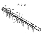
- Fig. 2 is a view showing in detail the heating furnace section of the dielectric heating apparatus 4.
- the heating furnace section comprises band heaters 13, leading wires 14 for supplying electric current to the band heaters 13, thermocouples 15 for measuring the temperature on the walls of the waveguide 7, and observation windows 16 for measuring the ambient temperature in the furnace and for observing the shape of the rod 1 under extension in the waveguide 7.
- six band heaters 13 each having a length of 50 cm are arranged on the outer periphery of the circular waveguide 7 to expand along the drawing direction, and similar band heaters 13 are arranged on the circular waveguides 8A, 8B, 9A and 9B, one for each of them, to cover the outer peripheries thereof.
- thermocouples 15 The temperatures on the wall of the waveguide 7 at the positions heated by respective band heaters 13 are monitored by thermocouples 15 to be controlled independently.
- the ambient temperature inside the furnace may be measured by inserting a temperature measuring device, such as a thermocouple, in the desired position of the furnace through one of the observation windows 16, prior to or after the emission of microwave.
- a temperature measuring device such as a thermocouple
- the dielectric heating furnace may be set to have a desired ambient temperature gradient along the drawing direction.
- the ambient temperature in the heating furnace is set to have a desired temperature gradient, and then a POM rod or tube 1 is fed from the feed reel 2 by the feeder 3 to pass through the dielectric heating furnace 4 where the rod or tube 1 is drawn under dielectric heating and then taken up by the take-up machine 11 to be wound around the take-up reel 12.
- the rod or tube 1 is dielectrically heated upon energization of the.microwave power source 5 and drawn continuously in the circular waveguide 7 under dielectric heating by the action of tension created by the difference between the take-up speed and the feed speed, since the rod or tube 1 is taken up by the take-up machine 11 at a speed far faster than the feed speed of the feeder 3.
- the crystalline molecular chains When a polymer material is drawn, the crystalline molecular chains are oriented with their molecular axes of crystals extending parallel to the drawing direction and the folded molecular chains are stretched to be reoriented to extend along the drawing direction.
- This phenomenon is known as the crystalline orientation in the art.
- tension is applied to the molecular chains in the amorphous regions existing between the crystalline regions to orient the molecular chains along hhe drawing direction.
- This phenomenon is known as the amorphous orientation in the art.
- the amorphous orientation contributes appreciably to the increase in tensile modulus. (In this connection, reference should be made to A. Ciferri and I. M. Ward (eds.), Ultra-High Modulus Polymers, Appl. Sci. Publishers, 1979).
- polymer materials exhibit a variety of dielectric absorptions of relaxation, including the crystalline absorption (a-absorption) caused by the motion of molecular chains in the crystalline region, the amorphous absorption ( ⁇ -absorption) caused by the motion of main chain in the amorphous region, and the absorption (y-absorption) caused by the local motion of the molecular chains in the amorphous region and in the crystal defects.
- a-absorption crystalline absorption
- ⁇ -absorption amorphous absorption
- y-absorption absorption caused by the local motion of the molecular chains in the amorphous region and in the crystal defects.
- the aforementioned a-, (3- and y-absorptions are initiated, in this order, as the frequency increases.
- the temperature and frequency for inducing these absorptions vary depending on the specific kind of the polymer material.
- the a-absorption occurs at low frequencies less than 1 Hz
- the P-absorption occurs at high frequencies 1 kHz to 1 MHz
- the y-absorption is induced by the microwave of about 1 GHz at a temperature around room temperature.
- These absorptions are enhanced and transferred to the higher frequency side, as the temperature becomes higher, and are .confused together at the melting point of the polymer material.
- These absorptions are excited by loading the polymer material with alternating current fields corresponding to the frequencies inducing respective absorptions to provide heat sources for dielectric heating.
- the ⁇ -absorption and/or the y-absorption may be selectively excited to heat the amorphous region selectively while leaving the crystalline region to be heated at a lesser extent.
- the crystalline region is heated due to heat conduction, as a matter of course.
- the microwave frequency for industrial use ranges within 13 MHz to 18 GHz, and the amorphous region is selectively heated by a microwave having a frequency within this range.
- the amorphous region of the POM rod or tube is heated by dielectric heating in the dielectric heating furnace. Since the calorific value of the heat generated at the amorphous region of the precursor rod or tube is large enough for heating the entire mass of the processed material, the tension applied on the rod or tube causes necking to draw the rod or pipe. Thereafter, the rod or tube is continuously drawn in the dielectric heating furnace so that the volume of the amorphous region is gradually decreased to reduce the calorific value of the heat generated by dielectric heating with the increase in heat emission from the surface of the slenderized rod or tube. As a result, the temperature of the processed material is lowered to make it difficult to rearrange the crystalline orientation.
- the ambient temperature distribution in the furnace is controlled such that the ambient temperature raises from a lower temperature to a higher temperature gradually along the drawing direction with a pre-set temperature gradient to suppress excessive heat emission in the course of drawing process, whereby the crystals contained in the processed material are continuously and effectively rearranged to improve the crystalline orientation.
- reduction in tensile modulus due to excessive heating of the crystalline regions can be suppressed because of the fact that the amorphous region is selectively heated more intensely than the crystalline region by means of dielectric heating.
- the drawing stress acts effectively upon the amorphous region resulting in effective amorphous orientation.
- a POM rod or tube is provided with ultrahigh orientation to have high tensile modulus while being produced through a continuous process.
- the precursor material must be processed under critical conditions for producing a product provided with such an ultrahigh orientation.
- the critical parameters for obtaining an ultrahigh-modulus material, such as a POM rod or tube, by drawing under dielectric heating are the ambient temperature, the electric field strength, the feed speed and the draw ratio between the feed speed and the take-up speed.
- the crystalline region is heated by heat conduction from the amorphous regions which has been selectively heated by dielectric heating. If the calorific value of the heat generated at the amorphous region is excessively large, the crystalline region is heated too rapidly to be reduced in tensile modulus so that the drawing stress developed in the amorphous region becomes insufficient for orienting the amorphous chains satisfactorily to attain improved amorphous orientation. For example, if the ambient temperature or the applied electric field strength is too high, the calorific value of the heat generated in the amorphous region becomes excessive, resulting in failure in effecting highly oriented rearrangement.
- the ambient temperature be low enough for selectively heating the amorphous region more intensively than the crystalline regions.
- the crystalline regions are not heated directly by dielectric heating, the crystalline regions must be heated by heat conduction at some extent so that the folded molecular chains in the crystals are reoriented to extend straight along the drawing direction by crystalline orientation.
- the temperature in the processed material is lowered to hinder the reorientation of crystals, as the drawing process proceeds with decrease of the amorphous region with attendant reduction in heat generated by dielectric heating and with decrease in diameter with attendant increase of heat emission from the surface of the slenderized rod or tube.
- the ambient temperature in the dielectric heating furnace be gradually raised from a lower temperature to a higher temperature along the drawing direction in order to facilitate reorientation of crystals.
- This temperature range corresponds to the range of crystalline relaxation temperature at which the molecular chains of polyoxymethylene in crystals become mobile. It should be appreciated hereby that the highest ambient temperature should be set at a temperature within the temperature range allowing the crystalline orientation. If the highest ambient temperature is set to a temperature lower than 120°C, the tensile modulus of the finished product becomes lower than 25 GPa since the reorientation of crystals is insufficient.
- Fig. 3 shows the changes in tensile modulus of the products obtained by using an embodiment of the apparatus for operating the process of this invention.
- a polyoxymethylene tube having an outer diameter of 3 mm and an inner diameter of 1 mm was drawn under an electric field strength of 360 V/cm and at a feed speed of 0.023 m/min., 0.05 m/min., 0.10 m/min., 0.20 m/min. or 0.50 m/min. while changing the highest ambient temperature.
- the tensile modulus of the resultant product changes depending on the highest ambient temperature.
- the tensile modulus of the resultant product obtained by drawing under dielectric heating also depends on the calorific value of the heat generated by dielectric heating, and the calorific value depends, in turn, on the electric field strength.
- a product having a tensile modulus of higher than 25 GPa, which is higher than the maximum value obtainable by the conventional processes, may be produced according to the process of this invention by setting the electric field strength within the range of from 200 to 550 V/cm.
- an electric field strength of 430 V/cm is developed by applying an output of 1 kW.
- the calorific value by dielectric heating must be equalized when a microwave power source generating a different frequency microwave is used.
- the calorific value by dielectric heating is in proportion to the product of the frequency and the square of electric field strength, and the pertinent range may be defined, as recited in the appended claim, within 9.8x 10'3 to 7.4x 10 14 Hz .
- V 2 /cm 2 when represented by the product of the frequency and the square of electric field strength.
- the calorific value by dielectric heating is less than the range defined as above, selective heating of the amorphous region cannot reach the level sufficient for obtaining a product having satisfactory ultrahigh-modulus, and the tensile modulus of the resultant product is lowered to the level which has been obtainable by the conventional hot drawing process.
- the calorific value by dielectric heating is in excess of the range defined above, selective heat generation in the amorphous region by dielectric heating cannot be attained and the entire mass is brought to have a temperature approximate to the melting point at which the mass is in the flow drawing state due to excessive heat generation. If the calorific value by dielectric heating is increased further, runaway heating inherent to the dielectric heating occurs to cause melting break to make it impossible to obtain a product having high tensile modulus.
- the tensile modulus changes depending on the electric field strength.
- the curves illustrated in Fig. 4 were obtained by plotting the tensile moduli measure while setting the highest ambient temperature to 140°C and setting the feed speed (m/min.) respectively to 0.05, 0.10, 0.20 and 0.50.
- the molecular chains tend to extend along the drawing direction under the action of drawing stress. This phenomenon or tendency is referred to as reorientation, and a certain time period is required for reorientation.
- the strain rate which is defined as the amount of strain per a unit time is too high, the molecular chains cannot be reoriented to result in the break of the material.
- the polymer material should be drawn under a condition at which the strain rate is as low as possible.
- the strain rate is the quotient of the speed difference between the take-up speed and the feed speed divided by the length of the furnace.
- ⁇ should take a larger value and y should take a smaller value, and hence the feed speed per a unit furnace length (v/L) should be set to a small value.
- Empirical studies conducted by us reveals that a polymer product having a tensile modulus of not less than 25 GPa which is beyond the tensile modulus obtainable by the conventional technology can be produced, in accordance with this invention, by setting the feed speed per a unit furnace length to not higher than 0.3 min.-' and by controlling the speed ratio of the take-up speed to the feed speed at a ratio of not less than twelve times.
- the tensile modulus of the product depends on the feed speed, as shown in Fig. 5; and the tensile modulus of the product also depends on the speed ratio of the take-up speed relative to the feed speed, as shown in Fig. 6.
- Polyoxymethylene having a density of 1.42 g/cm 3 , a melting point of 179°C, a number average molecular weight of 37,000 and a weight average molecular weight of 83,000 was used as the material for the crystalline polymer rod.
- a precursor rod 1 made of this material and having a diameter of 2.0 mm was fed into a dielectric heating apparatus 4 (Frequency: 2.45 GHz, Maximum Output: 1.5 KW, Circular Waveguide Length for Heating: 3 m, Inner Diameter: 95.6 mm).
- the ambient temperature in the vicinity of the inlet of the circular waveguide 7 for dielectric heating was set to 60°C, and the ambient temperature was gradually raised with an even temperature gradient along the drawing direction so that the ambient temperature reached to the highest temperature of 142°C in the vicinity of the outlet of the circular waveguide 7.
- the rod was fed into the circular waveguide 7 at a feed speed of 10 cm/min., and the draw ratio was gradually increased by increasing the take-up speed by the take-up machine 11 as the output (frequency: 2.45 GHz) from the microwave power source 5 was increased.
- the rod could be drawn to reach a draw ratio of 25 times under the condition at which the output from the power source 5 was increased to 1.0 kW and the take-up speed was increased to 2.5 m/min.
- the resultant filament had a diameter of 0.40 mm, and the linear expansion coefficient thereof took a negative small value of -4.Ox10-6 (° ⁇ ⁇ ).
- the tensile modulus of the filament was 34 GPa.
- the same precursor rod was separately drawn under dielectric heating in the same circular waveguide 7 generally following the procedures as described above, except in that the ambient temperature in the waveguide 7 is maintained, by external heating, at 146°C throughout the entire length of the waveguide 7 rather than changing the ambient temperature from 60°C to 142°C along a moderate temperature gradient.
- the process for producing an ultrahigh-modulus polymer according to this invention it is essential to heat the dielectric heating furnace or waveguide from the outside thereof in addition to dielectric heating, so as to obtain a gradient temperature increasing in the direction of drawing.
- the optimum condition for effective processing is determined by the parameters including the drawing speed, the output from the microwave power source and the concentration of polar molecules. The influences of the aforementioned parameters will now be discussed more in detail by referring to the following Examples.
- Example 2 a sample polymer was drawn under dielectric heating while heating the sample externally from the outside thereof and changing the output of the microwave power source.
- Each sample used in this Example was the same precursor rod made of the same crystalline polyoxymethylene as used in Example 1 and having a diameter of 2.0 mm, which was drawn in the same dielectric heating apparatus 4.
- the ambient temperature at the vicinity of the inlet of the circular waveguide 7 for dielectric heating was set to 55°C, and the ambient temperature was gradually raised along the drawing direction with a pre-set temperature gradient so that the ambient temperature at the vicinity of the outlet of the circular waveguide 7 was maintained at the highest temperature of 137°C.
- the feed speed was set to 10 cm/min., and the take-up speed was slowly increased with the increase of the output from the microwave power source 5. After the output from the power source 5 reached the pre-set value, respectively given in the following Table 1, the draw ratio was further increased by increasing the take-up speed at that output until the rod was broken.
- Table 1 The conditions for the experiments and the results obtained thereby are shown in Table 1.
- the draw ratio and the tensile modulus are dropped when the output from the power source exceeds beyond a certain value. It may be said from the results given above that the output from the power source should be selected within an optimum range for producing a product having an ultrahigh-modulus.
- a precursor tube made of a polyoxymethylene having a number average molecular weight of 37,000, a weight average molecular weight of 83,000, a density of 1.42 g/cm 3 and a melting point of 179°C was drawn under dielectric heating.
- the outer diameter of the tube was 3.0 mm, and the inner diameter of the tube was 1.0 mm.
- the used dielectric heating apparatus 4 comprised a microwave power source 5 for generating a microwave having a frequency of 2.45 GHz, the maximum output of the microwave power source 5 being 1.5 kW, a copper made circular waveguide (dielectric heating furnace) 7 for dielectric heating and having a length of 3 meters and an inner diameter of 95.6 mm, and other parts.
- the ambient temperature in the heating furnace was set to have a temperature gradient changing from 60°C at the center of the inlet section of the dielectric heating furnace through the sections heated to 90°C, 105°C, 120°C and 130°C to the highest ambient temperature of 130°C at the center of the outlet section of the dielectric heating furnace, by independently controlling six band heaters 13 mounted on the peripheral wall of the circular waveguide 7.
- the precursor tube 1 was fed from a feed reel 2 by means of a feeder 3 into the dielectric heating apparatus 4 where it was heated, and then passed to a take-up machine 11 to be clamped by the caterpillars of the take-up machine 11 from which the drawn product was passed to a take-up reel 12.
- the feed speed was set to 0.10 m/min: (feed speed per unit furnace length: 0.033 min- 1 ), and the feed speed was fixed to that speed constantly during the drawing operation.
- the output from the power source at the initial stage was 0.22 kW (electric field strength: 200 V/cm).
- a 3-points bending type tensiometer was interposed between the dielectric heating apparatus 4 and the take-up machine 11 to monitor the tension applied on the pipe 1 during the drawing operation.
- An outer diameter measuring device was disposed between the take-up machine 11 and the take-up reel 12 to monitor the outer diameter of the drawn pipe.
- the take-up speed was controlled, after the commencement of drawing operation, to adjust the tension to 10 kg.
- the take-up speed had to be changed greatly at the initial stage to maintain the tension at the aforementioned constant value, since the tube was drawn to be lengthened significantly at the drawing point (necking point). However, after the drawing point was fixed, the take-up speed could be set to a constant value, and the steady state operation was continued at a take-up speed of 0.8 m/min. under the constant tension of 10 kg. After the outer diameter of the drawn tube was stabilized at a constant value, the output of the power source was raised to the final value of 0.57 kW (electric field strength: 320 V/cm.) The temperature of the processed material was raised as the output of the power source was increased, whereby the tension was reduced.
- the take-up speed was increased to maintain the tension at 10 kg, and steady state operation was continued at a take-up speed at 1.2 m/min.
- the take-up speed was further increased at some extent, whereby the tension applied to the tube was somewhat increased and the outer diameter of the tube became thinner.
- the take-up speed was further increased to produce a thinner tube. The aforementioned operation was repeated to increase the take-up speed, and finally the tube could be drawn at a take-up speed of 1.4 m/min. which corresponds to 14 times as high as the feed speed.
- the tube was broken when the take-up speed was increased beyond the draw ratio thereof to the feed speed of 14.
- the drawing tension at that time was 11 kg.
- the output from the microwave power source was set to the final value of 0.57 kW immediately after the initiation of drawing operation
- the calorific value of the heat generated by dielectric heating became excessively large nevertheless the drawing point had not yet been stabilized to cause melting break due to runaway heating.
- the take-up speed was set to the final take-up speed of 1.4 m/min. immediately after the initiation of drawing operation, the strain rate became excessively large to cause breakage of the tube.
- the output from the microwave power source and the take-up speed should be set to lower levels at the initial stage for drawing the tube under dielectric heating, and that the output and the take-up speed must be gradually raised after the drawing point is fixed to continue the stabilized operation.
- the outer diameter of the resultant drawn tube was 0.81 mm, and the tensile modulus thereof at the room temperature was 28.5 GPa.
- the condition under which the polyoxymethylene tube was drawn under dielectric heating are shown in Table 2.
- Example 2 The same polyoxymethylene tube as used in Example 1 was drawn in the same dielectric heating furnace as used in Example 3, while setting the ambient temperature in the heating furnace to a temperature higher than the ambient temperature in Example 3, more specifically the ambient temperature at the center of the inlet of the furnace being 70°C, the ambient temperature to the subsequent sections arranged successively toward the outlet being, respectively, set to 105°C, 115°C, 130°C and 140°C and the highest ambient temperature at the center of the outlet being set to 140°C (See Table 2 No. 12). Similar to Example 1, the feed speed was set to 0.10 m/min.
- the take-up speed was controlled to apply a tension of 9 kg to the tube at the initial stage of drawing operation.
- the output of the power source was gradually raised, similar to Example 3, to the final value of 0.57 kW and concurrently the take-up speed was raised so that the constant tension of 9 kg was applied to the tube.
- the take-up speed was raised repeatedly after the outer diameter of the drawn tube took a stable value at every operation.
- the tube could be drawn at a take-up speed of 2.0 m/min. and at a draw ratio oftake-up speed to the feed speed of 20 times.
- the tube was broken when the take-up speed was further increased beyond aforementioned value.
- the drawing tension at that was 11.5 kg.
- the resultant drawn tube had an outer diameter of 0.67 mm and a tensile modulus of 44.8 GPa.
- the tensile modulus (44.8 GPa) was improved over that obtained by Example 3 (28.5 GPa) by raising the highest ambient temperature by 10°C, namely from 130°C to 140°C.
- Example 3 The same polyoxymethylene tube as used in Example 3 was drawn in the same dielectric heating furnace as used in Example 3, while setting the highest ambient temperature in the heating furnace further higher than the highest ambient temperature as set in Example 4 by additional 5°C or 10°C throughout all sections, more specifically the ambient temperature at the inlet of the furnace being 80°C, the ambient temperatures in the sections arranged successively toward the outlet of the furnace being, respectively, set to 110°C, 125°C, 135°Cand 145°C, and the highest ambient temperature at the outlet of the furnace being set to 145°C (See Table 2 No. 13). Similar to Example 3, the feed speed was set to 0.10 m/min., and the output from the microwave power source at the initial stage of drawing operation was set to 0.22 kW.
- the take-up speed was controlled to apply a tension of 9 kg to the tube at the initial stage of drawing operation. After the drawing point was fixed and the outer diameter of the drawn tube was stabilized to have a constant value, the output of the power source was gradually raised to the final value of 0.57 kW and concurrently the take-up speed was raised so that the constant tension of 9 kg was applied to the tube. The take-up speed was raised repeatedly after the outer diameter of the drawn tube took a constant value. Finally, the tube could be drawn at a take-up speed of 2.3 m/min. and at a draw ratio of 23 times. The tube was broken when the take-up speed was further increased beyond the aforementioned value. The drawing tension at that time was 10.5 kg.
- the resultant tube had an outer diameter of 0.65 mm and a tensile modulus of 42.1 GPa.
- the draw ratio could be raised from 20 times (Example 4) to 23 times by raising the highest ambient temperature from 140°C (Example 4) to 145°C, the tensile modulus of the product was rather lowered from 44.8 GPa (Example 4) to 42.1 GPa. It is considered that the temperature of the entire mass of the sample polymer was raised too high to render the mass partially to be in flow drawing state, leading to reduction in tensile modulus of the product, since the highest ambient temperature in this Example was too high.
- Example 3 The same polyoxymethylene tube as used in Example 3 was drawn under dielectric heating in the same dielectric heating furnace as used in Example 3, while setting the ambient temperature in the heating furnace to the same temperature as in Example 4, namely the ambient temperature at the inlet of the furnace being set to 70°C, the ambient temperature in the sections arranged successively toward the outlet of the furnace being, respectively, set to 105°C, 115°C, 130°C and 140°C, and the highest ambient temperature at the outlet of the furnace being set to 140°C (See Table 2 No. 9).
- the tube was drawn under dielectric heating while changing the final value of the output from the microwave power source to 0.34 kW (electric field strength: 250 V/cm).
- the feed speed was set to 0.10 m/min., and the output from the microwave power source at the initial stage of drawing operation was set to 0.22 kW.
- the take-up speed was controlled so that a tension of 10 kg was applied to the tube at initial stage of drawing operation. After the drawing point was fixed and the outer diameter of the drawn tube was stabilized to have a constant value, the output was gradually raised to the final value of 0.34 kW and the take-up speed was increased correspondingly to maintain the tension of 10 kg. The take-up speed was further increased, after the outer diameter of the drawn tube took a constant value. The last-mentioned operation was repeated. Finally, the tube could be drawn at a take-up speed of 1.7 m/min.
- Example 8 The same polyoxymethylene tube as used in Example 8 was drawn under dielectric heating in the same dielectric heating furnace as used in Example 3, while setting the feed speed to 0.50 m/min. (feed speed per unit furnace length: 0.17 min.-') and setting the ambient temperature in the dielectric heating furnace at 60°C, 120°C, 125°C, 140°C, 145°C and 150°C in respective sections arranged from the inlet to the outlet of the furnace in that order. Thus, the highest ambient temperature at the outlet of the furnace was 150°C.
- the output from the microwave power source at the initial stage of drawing operation was set to 0.22 kW similar to Example 3, and the take-up speed was controlled so that a tension of 7 kg was applied to the tube at the initial stage.
- the output was increased up to the final value of 0.70 kW (electric field strength: 360 V/cm) and concurrently the take-up speed was increased.
- the tube could be drawn at a take-up speed of 10 m/min. and at a draw ratio of 20 times. However, the tube was broken when the take-up speed was increased beyond the aforementioned speed.
- the resultant tube had an outer diameter of 0.67 mm and a tensile modulus of 35.4 GPa.
- Example 3 The same polyoxymethylene tube as used in Example 3 was drawn under dielectric heating in the same dielectric heating furnace as used in Example 3, while setting the feed speed to 0.023 m/min (feed j speed per unit furnace length: 0.008 min.-') and setting the ambient temperature in the dielectric heating furnace at 35°C, 60°C, 85°C, 110°C, 125°C and 135°C in respective sections arranged from the inlet to the outlet of the furnace in that order (See Table 2 No. 23). Thus, the highest ambient temperature at the outlet of the furnace was 135°C. In this Example, no tensiometer was provided.
- the drawing operation was commenced while setting the output from the microwave power source to 0.07 kW (electric field strength: 110 V/cm) and the take-up speed to 0.14 (Draw Ratio: 6 times). After the outer diameter of the drawn tube was stabilized to have a constant value, the take-up speed was increased at some extent while maintaining the output at the fixed value of 0.07 kW. Whereupon, the outer diameter of the drawn tube became slenderer correspondingly. After the outer diameter of the drawn tube was stabilized again, the take-up speed was increased further. The aforementioned operation was repeated to increase the take-up speed to 0.44 m/min. thereby to raise the draw ratio to 19 times.
- the output from the microwave power source was gradually raised up to the final value of 0.70 kW (electric field strength: 360 V/cm) while maintaining the take-up speed at the fixed speed of 0.44 m/min. Thereafter, the take-up speed was increased stepwisely. Finally, the tube could be drawn at a take-up speed of 0.70 m/min. and at a draw ratio of 30 times. However, the tube was broken when the take-up speed was increased to 0.72 m/min. The resultant drawn tube had an outer diameter of 0.60 mm and a tensile modulus of 63.1 GPa.
- a rod made of the polyoxymethylene described in Example 3 and having a diameter of 2.4 mm was . drawn under dielectric heating.
- the used dielectric heating apparatus was the same as used in Example 3.
- the feed speed was set to 0.056 m/min. (feed speed per unit furnace length: 0.019 min.-').
- the ambient temperature in the dielectric heating furnace was set at 35°C, 60°C, 85°C, 110°C, 125°C and 135°C in respective sections arranged serially from the inlet to the outlet of the furnace in that order. Thus, the highest ambient temperature at the outlet of the furnace was 135°C.
- no tensiometer was provided. The drawing operation was commenced while setting the output from the microwave power source to 0.07 kW (electric Field Strength: 110 V/cm) and the take-up speed to 0.34 (draw ratio: 6 times). After the diameter of the drawn rod was stabilized to have a constant value, the take-up speed was increased at some extent while maintaining the output at the fixed value of 0.07 kW.
- the diameter of the drawn rod was stabilized again at the thus increased take-up speed. Then the take-up speed was increased again at some extent.
- the aforementioned operation sequence was repeated to increase the take-up speed to 0.90 m/min. thereby to raise the draw ratio to 16 times. Thereafter, the output from the microwave power source was gradually raised up to the final value of 0.70 kW (electric field strength: 360 V/cm) while maintaining the take-up speed at the fixed speed of 0.90 m/min. Then, the take-up speed was increased stepwisely. Finally, the rod could be drawn at a take-up speed of 1.56 m/min. and at a speed ratio of 28 times. However, the rod was broken when the take-up speed was increased to 1.60 m/min. The resultant drawn rod had a diameter of 0.48 mm and a tensile modulus of 56.0 GPa.
- a tube or rod made of polyoxymethylene is drawn under dielectric heating while maintaining the ambient temperature at an elevated temperature by external heating with a gradient in the direction of drawing, and while setting the feed speed and the draw ratio of the feed speed to the take-up speed to defined speed and ratio, whereby a tube or rod product having an ultrahigh-modulus, such as a tensile modulus of higher than 25 GPa, which is superior to the value obtainable by any of the conventional techniques can be continuously produced at a relatively high production speed.
- an ultrahigh-modulus such as a tensile modulus of higher than 25 GPa
- a product in the form of filament, rod, tube or tape produced by the process of this invention may be used for various applications.
- a filament produced in accordance with this invention may be used as a reinforcing material or filler in a variety of composite materials.
- Materials produced by the process of this invention may be used for various applications wherein light weight, small linear expansion coefficient and high tensile modulus are required. It is particularly advantageous to use the product of this invention as a coating material for optical fibers or as a reinforcing material for various applications where it is required that the shrinkage due to temperature drop is as small as possible.
Landscapes
- Physics & Mathematics (AREA)
- Thermal Sciences (AREA)
- Engineering & Computer Science (AREA)
- Mechanical Engineering (AREA)
- Health & Medical Sciences (AREA)
- Oral & Maxillofacial Surgery (AREA)
- Electromagnetism (AREA)
- Shaping By String And By Release Of Stress In Plastics And The Like (AREA)
Claims (3)
Applications Claiming Priority (6)
| Application Number | Priority Date | Filing Date | Title |
|---|---|---|---|
| JP208032/81 | 1981-12-24 | ||
| JP20803181A JPH0236700B2 (ja) | 1981-12-24 | 1981-12-24 | Purasuchitsukunoenshinhoho |
| JP20803281A JPS58109617A (ja) | 1981-12-24 | 1981-12-24 | ポリオキシメチレンロツドの延伸方法 |
| JP208031/81 | 1981-12-24 | ||
| JP21815282A JPS59106921A (ja) | 1982-12-13 | 1982-12-13 | 高弾性率のポリオキシメチレンよりなるロツドまたはパイプの製造方法 |
| JP218152/82 | 1982-12-13 |
Publications (2)
| Publication Number | Publication Date |
|---|---|
| EP0084274A1 EP0084274A1 (de) | 1983-07-27 |
| EP0084274B1 true EP0084274B1 (de) | 1988-02-24 |
Family
ID=27328835
Family Applications (1)
| Application Number | Title | Priority Date | Filing Date |
|---|---|---|---|
| EP82307041A Expired EP0084274B1 (de) | 1981-12-24 | 1982-12-22 | Verfahren zur Herstellung von Polymeren mit sehr hohem Elastizitätsmodul |
Country Status (3)
| Country | Link |
|---|---|
| US (1) | US4497759A (de) |
| EP (1) | EP0084274B1 (de) |
| DE (1) | DE3278134D1 (de) |
Families Citing this family (8)
| Publication number | Priority date | Publication date | Assignee | Title |
|---|---|---|---|---|
| US4902461A (en) * | 1987-03-20 | 1990-02-20 | Barmag, Ag | Method for heating an advancing yarn |
| EP0914933B1 (de) * | 1997-11-04 | 2002-02-20 | Tenax S.p.A. | Verfahren zum Strecken von Kunststoff-Netzen und -Gittern |
| US9603203B2 (en) | 2013-11-26 | 2017-03-21 | Industrial Microwave Systems, L.L.C. | Tubular waveguide applicator |
| US9642194B2 (en) | 2014-08-07 | 2017-05-02 | Industrial Microwave Systems, L.L.C. | Tubular choked waveguide applicator |
| TWI665349B (zh) * | 2018-01-29 | 2019-07-11 | 永虹先進材料股份有限公司 | Fiber pre-oxidation equipment |
| PL3946942T3 (pl) | 2019-03-28 | 2025-04-28 | Philip Morris Products S.A. | Urządzenie do formowania i sposób formowania ciągłego pręta rurowego |
| TWI875846B (zh) | 2019-10-25 | 2025-03-11 | 美商應用材料股份有限公司 | 電漿增強處理中的rf功率源操作 |
| US12000049B2 (en) | 2021-12-22 | 2024-06-04 | Rtx Corporation | Alternating and continuous microwave fiber tow coating thermo-chemical reactor furnace |
Family Cites Families (4)
| Publication number | Priority date | Publication date | Assignee | Title |
|---|---|---|---|---|
| BE627777A (de) * | 1962-01-30 | |||
| GB1065971A (en) * | 1964-03-07 | 1967-04-19 | Elliott Electronic Tubes Ltd | Extruded material heater and heating process |
| US3364294A (en) * | 1965-09-20 | 1968-01-16 | Monsanto Co | Filament orientation process |
| DE2019599B2 (de) * | 1970-04-23 | 1971-12-02 | Menschner Textil Johannes | Vorrichtung zur behandlung von thermisch beeinflussbarem behandlungsgut unter einwirkung von mikrowelllenenergie |
-
1982
- 1982-12-22 EP EP82307041A patent/EP0084274B1/de not_active Expired
- 1982-12-22 DE DE8282307041T patent/DE3278134D1/de not_active Expired
- 1982-12-23 US US06/452,862 patent/US4497759A/en not_active Expired - Fee Related
Also Published As
| Publication number | Publication date |
|---|---|
| EP0084274A1 (de) | 1983-07-27 |
| US4497759A (en) | 1985-02-05 |
| DE3278134D1 (en) | 1988-03-31 |
Similar Documents
| Publication | Publication Date | Title |
|---|---|---|
| US4477707A (en) | Electromagnetic field heating apparatus for curing resin/fiber composites in continuous pultrusion processes | |
| EP0084274B1 (de) | Verfahren zur Herstellung von Polymeren mit sehr hohem Elastizitätsmodul | |
| US5096634A (en) | Method of operating an apparatus for the production of biaxially stretched plastic tubes | |
| EP0300321A2 (de) | Verfahren zur kontinuierlichen Herstellung faserverstärkter thermoplastischer Prepregs und Vorrichtung zur Durchführung desselben | |
| RU2053124C1 (ru) | Способ изготовления композиционного изделия | |
| US6020579A (en) | Microwave applicator having a mechanical means for tuning | |
| US3558580A (en) | Thin oriented plastic strips and tape | |
| US2296394A (en) | Manufacture of novelty artificial yarn | |
| US6121595A (en) | Applicator to provide uniform electric and magnetic fields over a large area and for continuous processing | |
| US4541979A (en) | Process and apparatus for manufacturing optical cable elements | |
| EP0170491A2 (de) | Herstellung von Lichtwellenleiterkabel | |
| DE202005001756U1 (de) | Mikrowellensensor zur Messung einer dielektrischen Eigenschaft eines Produkts | |
| US5213843A (en) | Vacuum powder injector and method of impregnating fiber with powder | |
| US4780585A (en) | Method and device for the thermal treatment of a conductor element at least partially constituted by a conducting material | |
| GB2053629A (en) | Process and Device for the Heat Treatment of Filiform Elements | |
| CA1197966A (en) | Process for the production of ultrahigh-modulus polymers | |
| JPH0129695B2 (de) | ||
| US5302411A (en) | Process for vulcanizing insulated wire | |
| JPS6361760B2 (de) | ||
| US3755519A (en) | Process for the preparation of weavable crosslinked and carbon filledpolyolefin filaments | |
| JPH0236700B2 (ja) | Purasuchitsukunoenshinhoho | |
| JPS6135281B2 (de) | ||
| EP0622344B1 (de) | Vorrichtung mit grosser Blende zur Überwachung der Dicke einer leitenden Beschichtung auf optischen Fasern | |
| US2954815A (en) | Method and apparatus for assembling rubber threads into ribbons | |
| Fathi et al. | Industrial applications of variable frequency microwave energy in materials processing |
Legal Events
| Date | Code | Title | Description |
|---|---|---|---|
| PUAI | Public reference made under article 153(3) epc to a published international application that has entered the european phase |
Free format text: ORIGINAL CODE: 0009012 |
|
| AK | Designated contracting states |
Designated state(s): DE FR GB IT NL |
|
| 17P | Request for examination filed |
Effective date: 19830726 |
|
| RAP1 | Party data changed (applicant data changed or rights of an application transferred) |
Owner name: NIPPON TELEGRAPH AND TELEPHONE CORPORATION |
|
| GRAA | (expected) grant |
Free format text: ORIGINAL CODE: 0009210 |
|
| AK | Designated contracting states |
Kind code of ref document: B1 Designated state(s): DE FR GB IT NL |
|
| ITF | It: translation for a ep patent filed | ||
| REF | Corresponds to: |
Ref document number: 3278134 Country of ref document: DE Date of ref document: 19880331 |
|
| ET | Fr: translation filed | ||
| PLBE | No opposition filed within time limit |
Free format text: ORIGINAL CODE: 0009261 |
|
| STAA | Information on the status of an ep patent application or granted ep patent |
Free format text: STATUS: NO OPPOSITION FILED WITHIN TIME LIMIT |
|
| 26N | No opposition filed | ||
| PGFP | Annual fee paid to national office [announced via postgrant information from national office to epo] |
Ref country code: GB Payment date: 19921102 Year of fee payment: 11 |
|
| PGFP | Annual fee paid to national office [announced via postgrant information from national office to epo] |
Ref country code: FR Payment date: 19921130 Year of fee payment: 11 |
|
| PGFP | Annual fee paid to national office [announced via postgrant information from national office to epo] |
Ref country code: DE Payment date: 19921222 Year of fee payment: 11 |
|
| ITTA | It: last paid annual fee | ||
| PGFP | Annual fee paid to national office [announced via postgrant information from national office to epo] |
Ref country code: NL Payment date: 19921231 Year of fee payment: 11 |
|
| PG25 | Lapsed in a contracting state [announced via postgrant information from national office to epo] |
Ref country code: GB Effective date: 19931222 |
|
| PG25 | Lapsed in a contracting state [announced via postgrant information from national office to epo] |
Ref country code: NL Effective date: 19940701 |
|
| NLV4 | Nl: lapsed or anulled due to non-payment of the annual fee | ||
| GBPC | Gb: european patent ceased through non-payment of renewal fee |
Effective date: 19931222 |
|
| PG25 | Lapsed in a contracting state [announced via postgrant information from national office to epo] |
Ref country code: FR Effective date: 19940831 |
|
| PG25 | Lapsed in a contracting state [announced via postgrant information from national office to epo] |
Ref country code: DE Effective date: 19940901 |
|
| REG | Reference to a national code |
Ref country code: FR Ref legal event code: ST |