EP0084294A2 - Betätigungseinrichtung für Schienenfahrzeugbremsen oder dergleichen, mit automatischer Spielnachstellungsvorrichtung - Google Patents
Betätigungseinrichtung für Schienenfahrzeugbremsen oder dergleichen, mit automatischer Spielnachstellungsvorrichtung Download PDFInfo
- Publication number
- EP0084294A2 EP0084294A2 EP82830199A EP82830199A EP0084294A2 EP 0084294 A2 EP0084294 A2 EP 0084294A2 EP 82830199 A EP82830199 A EP 82830199A EP 82830199 A EP82830199 A EP 82830199A EP 0084294 A2 EP0084294 A2 EP 0084294A2
- Authority
- EP
- European Patent Office
- Prior art keywords
- rod
- threaded rod
- hollow shaft
- tubular casing
- sleeve
- Prior art date
- Legal status (The legal status is an assumption and is not a legal conclusion. Google has not performed a legal analysis and makes no representation as to the accuracy of the status listed.)
- Granted
Links
Images


Classifications
-
- F—MECHANICAL ENGINEERING; LIGHTING; HEATING; WEAPONS; BLASTING
- F16—ENGINEERING ELEMENTS AND UNITS; GENERAL MEASURES FOR PRODUCING AND MAINTAINING EFFECTIVE FUNCTIONING OF MACHINES OR INSTALLATIONS; THERMAL INSULATION IN GENERAL
- F16D—COUPLINGS FOR TRANSMITTING ROTATION; CLUTCHES; BRAKES
- F16D65/00—Parts or details
- F16D65/38—Slack adjusters
- F16D65/40—Slack adjusters mechanical
- F16D65/52—Slack adjusters mechanical self-acting in one direction for adjusting excessive play
- F16D65/56—Slack adjusters mechanical self-acting in one direction for adjusting excessive play with screw-thread and nut
-
- B—PERFORMING OPERATIONS; TRANSPORTING
- B60—VEHICLES IN GENERAL
- B60T—VEHICLE BRAKE CONTROL SYSTEMS OR PARTS THEREOF; BRAKE CONTROL SYSTEMS OR PARTS THEREOF, IN GENERAL; ARRANGEMENT OF BRAKING ELEMENTS ON VEHICLES IN GENERAL; PORTABLE DEVICES FOR PREVENTING UNWANTED MOVEMENT OF VEHICLES; VEHICLE MODIFICATIONS TO FACILITATE COOLING OF BRAKES
- B60T17/00—Component parts, details, or accessories of power brake systems not covered by groups B60T8/00, B60T13/00 or B60T15/00, or presenting other characteristic features
- B60T17/08—Brake cylinders other than ultimate actuators
- B60T17/081—Single service brake actuators
-
- B—PERFORMING OPERATIONS; TRANSPORTING
- B60—VEHICLES IN GENERAL
- B60T—VEHICLE BRAKE CONTROL SYSTEMS OR PARTS THEREOF; BRAKE CONTROL SYSTEMS OR PARTS THEREOF, IN GENERAL; ARRANGEMENT OF BRAKING ELEMENTS ON VEHICLES IN GENERAL; PORTABLE DEVICES FOR PREVENTING UNWANTED MOVEMENT OF VEHICLES; VEHICLE MODIFICATIONS TO FACILITATE COOLING OF BRAKES
- B60T17/00—Component parts, details, or accessories of power brake systems not covered by groups B60T8/00, B60T13/00 or B60T15/00, or presenting other characteristic features
- B60T17/08—Brake cylinders other than ultimate actuators
- B60T17/083—Combination of service brake actuators with spring loaded brake actuators
-
- B—PERFORMING OPERATIONS; TRANSPORTING
- B61—RAILWAYS
- B61H—BRAKES OR OTHER RETARDING DEVICES SPECIALLY ADAPTED FOR RAIL VEHICLES; ARRANGEMENT OR DISPOSITION THEREOF IN RAIL VEHICLES
- B61H15/00—Wear-compensating mechanisms, e.g. slack adjusters
-
- B—PERFORMING OPERATIONS; TRANSPORTING
- B61—RAILWAYS
- B61H—BRAKES OR OTHER RETARDING DEVICES SPECIALLY ADAPTED FOR RAIL VEHICLES; ARRANGEMENT OR DISPOSITION THEREOF IN RAIL VEHICLES
- B61H5/00—Applications or arrangements of brakes with substantially radial braking surfaces pressed together in axial direction, e.g. disc brakes
-
- F—MECHANICAL ENGINEERING; LIGHTING; HEATING; WEAPONS; BLASTING
- F16—ENGINEERING ELEMENTS AND UNITS; GENERAL MEASURES FOR PRODUCING AND MAINTAINING EFFECTIVE FUNCTIONING OF MACHINES OR INSTALLATIONS; THERMAL INSULATION IN GENERAL
- F16D—COUPLINGS FOR TRANSMITTING ROTATION; CLUTCHES; BRAKES
- F16D55/00—Brakes with substantially-radial braking surfaces pressed together in axial direction, e.g. disc brakes
- F16D55/02—Brakes with substantially-radial braking surfaces pressed together in axial direction, e.g. disc brakes with axially-movable discs or pads pressed against axially-located rotating members
- F16D55/22—Brakes with substantially-radial braking surfaces pressed together in axial direction, e.g. disc brakes with axially-movable discs or pads pressed against axially-located rotating members by clamping an axially-located rotating disc between movable braking members, e.g. movable brake discs or brake pads
- F16D55/224—Brakes with substantially-radial braking surfaces pressed together in axial direction, e.g. disc brakes with axially-movable discs or pads pressed against axially-located rotating members by clamping an axially-located rotating disc between movable braking members, e.g. movable brake discs or brake pads with a common actuating member for the braking members
- F16D55/2245—Brakes with substantially-radial braking surfaces pressed together in axial direction, e.g. disc brakes with axially-movable discs or pads pressed against axially-located rotating members by clamping an axially-located rotating disc between movable braking members, e.g. movable brake discs or brake pads with a common actuating member for the braking members in which the common actuating member acts on two levers carrying the braking members, e.g. tong-type brakes
Definitions
- the present invention relates to actuators for controlling the brakes of railway vehicles or the like.
- the invention concerns an actuator comprising a tubular casing defining at one end a cylinder in which is slidable, under the effect of a fluid under pressure and against the action of resilient return means, a piston carrying a hollow shaft in which a rod for operating the brake means is coupled axially, and an automatic device for taking up play which is associated with the rod and acts so as to vary the axial position of the rod relative to the hollow shaft following wear of the brake means.
- the object of the present invention is to provide an actuator of the aforesaid type, which is simple, practical and is constituted by a smaller number of parts and is therefore particularly simple and economical to manufacture.
- the invention provides a control actuator for brakes of railway vehicles; characterised in that:
- the actuator according to the invention may be provided with a spring-operated device which acts on the piston to effect parking or emergency braking automatically.
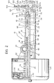
- a pneumatic actuator for controlling a brake caliper 12 carrying a pair of friction shoes 14 which cooperate with a wheel 16 of a railway vehicle or the like.
- the actuator 10 comprises essentially a tubular cylindrical casing 18 to one end of which is fixed a cylinder 20 arranged to be supplied, through an inlet union 22, from a source of air under pressure.
- a piston 26 is sealingly slidable against the action of a helical compression spring 24.
- a hollow shaft 28 which extends within the tubular casing 18.
- an attachment bush 30 for the articulation of one of the arms 12a of the brake caliper 12.
- the attachment bush 30 projects into the cavity of the tubular casing 18 and slidably engages an axial flat 32 formed on the outer surface of the hollow shaft 28. Thus, the latter is locked against rotation relative to the tubular casing 18.
- An externally-threaded rod is shown as 34, with its inner end extending coaxially in the hollow shaft 28 and its outer end projecting from the tubular casing 18 at the opposite side from the cylinder 20.
- An internally-threaded stop member 36 is engaged on the threaded rod 34, and inserted slidably in an internal annular recess 38 formed at the end of the hollow shaft 28 opposite the piston 26.
- the stop member 36 has a frontal conical surface 40 facing a complementary frontal conical surface 42 of the recess 38.
- the two frontal surfaces 40, 42 are provided with respective frontal coupling teeth, by means of which the annular stop member 36 is locked against rotation relative to the hollow shaft 28.
- the end face of the annular stop member 36 opposite the surface 40 bears against an axial rolling bearing 44 subject to the action of an axial helical compression spring 46 which acts against an annular stop 48 carried at the free end of the hollow shaft 28.
- the spring 46 urges the annular stop member 36 axially in the direction of the piston 26, so as to maintain the frontal surfaces 40, 42 in mutual engagement.
- An annular friction member, generally indicated 50, is interposed coaxially between the tubular casing 18 and the threaded rod 34 close to the outer end of the latter.
- the friction member 50 comprises an external sleeve 52 which faces the internal wall of the tubular casing 18 and has an axial projection 54 at one end in sliding contact with the threading of the rod 34, and an internal sleeve 56 axially locked with respect to the sleeve 52 and facing the surface of the rod 34.
- the internal sleeve 56 has a series of axial slits, not shown in the drawings, so as to be radially contractable, and has a series of annular circumferential grooves 59 in its outer surface in each of which is engaged a resilient ring 60 tending to clamp the sleeve 58 against the rod 34.
- the friction member 50 may move axially with the rod 34 for a predetermined length of travel between a pair of stops 62, 64.
- the stop 62 is constituted by a resilient ring which engages an annular internal groove 66 formed in the internal surface of the tubular casing 18, while the stop 64 is formed by an externally-threaded ring which is screwed onto internal threading 68 at the free end of the tubular casing 18.
- the screwing or unscrewing of the threaded ring 64 relative to the casing 18 allows the amount of displacement of the friction member 50 to be varied according to the requirements of use.
- the locking of the ring 64 relative to the casing 18 in a predetermined position is effected by a set screw 65.
- the threaded rod 34 has an axial stub portion 70 at its free end with an initial section with a thread 72.
- the thread 72 is engaged with an internally-threaded boss 74 of a sleeve 76 shown in detail in Figure 3.
- the sleeve 76 is provided, at its frontal face which faces outwardly of the tubular casing 18, with a ring of axial detents 78 the function of which will be clarified below.
- the side wall of the sleeve 76 is fixed rigidly to the outer end of a tubular guard 80 which surrounds the outer surface of the tubular casing 18 with clearance.
- the tubular part 84 of the body 82 is inserted coaxially in the cavity of the sleeve 76, and a rolling bearing 90 is interposed between the two elements to allow the free rctation of the sleeve 76 relative to the body 82.
- a transverse attachment bush 92 similar to the attachment bush 30, is fixed rigidly to the body 82 and serves for the connection of the other arm 12b of the brake caliper 12. Furthermore, the body 82 is provided with a hook member, indicated 94, the function of which is to unlock the sleeve 76, and hence the threaded rod 34, for rotation relative to the body 82. As illustrated in detail in Figures 2 and 3, the hook member 94 is formed from a pin spring which is wound around a cylindrical support 96 fixed transversely to the body 82, and has an arm 94a acting against the outer surface of the attachment bush 92.
- the other arm of the spring 94 extends axially through a recess 98 in the upper part of the body 82 and engages the frontal detents 78 of the sleeve 76.
- a control member 100 is connected to the arm 94b and is formed from a bar 102 which is provided with an annular handle 104 and extends through a guide and protection sleeve 106 within the axial recess 98.
- the internal end of the bar 1C2, indicated 102a is bent about the arm 94b of the spring 94.
- the actuator according to the invention is able to achieve automatically a continuous take-up of the play due to the wear of the friction shoes 14. Indeed, during operation of the actuator, at the end of the travel of the friction member 50, whenever the friction shoes 14 are no longer in braking contact with the wheel 16 because of wear, the rod 34 slides axially, sliding relative to the internal sleeve 56 of the friction member 50, so as to bring the shoes 14 into contact with the wheel 16 and thus apply the braking force.
- the rod 54 When the actuator is deactivated, the rod 54 lies in a different axial position relative to the hollow shaft 28, being displaced outwardly relative to the latter, so as to take up the initial travel of the displacement. Indeed, during the initial return phase of the rod 34 towards the rest position of Figure 2, the friction member 50 is brought back, under the action of the spring 24, against the stop ring 62. In this position, the rod 34 is displaced axially relative to the friction member 50 by a value corresponding to the previous additional braking travel. The return travel of the piston 26 continuing, the rod 34 is locked axially by the friction member 50 while the tubular shaft 28 continues its displacement towards the left, sliding relative to the rod 34 and separating from the annular stop member 36. The helical spring 46 is then compressed and, due to its axial thrust, the stop member 36 is rotated, screwing onto the threaded rod 34 so as to renew the engagement between the coupling surfaces 40, 42.
- the actuator according to the invention is provided with a spring-operated device which acts on the piston 26 to achieve parking or emergency braking automatically.
- the cylinder 20 forms an auxiliary chamber 110 behind the chamber in which the piston 26 is movable, an auxiliary piston 112 being slidable in this auxiliary chamber and to which is fixed a shaft 114 which bears against the surface of the piston 26.
- the auxiliary chamber 110 is connected permanently to the source of air under pressure which supplies the actuator.
Landscapes
- Engineering & Computer Science (AREA)
- Mechanical Engineering (AREA)
- General Engineering & Computer Science (AREA)
- Transportation (AREA)
- Braking Arrangements (AREA)
- Regulating Braking Force (AREA)
Priority Applications (1)
| Application Number | Priority Date | Filing Date | Title |
|---|---|---|---|
| AT82830199T ATE18651T1 (de) | 1982-01-15 | 1982-07-07 | Betaetigungseinrichtung fuer schienenfahrzeugbremsen oder dergleichen, mit automatischer spielnachstellungsvorrichtung. |
Applications Claiming Priority (2)
| Application Number | Priority Date | Filing Date | Title |
|---|---|---|---|
| IT6704182 | 1982-01-15 | ||
| IT67041/82A IT1154432B (it) | 1982-01-15 | 1982-01-15 | Attuatore di comando per freni di veicoli ferroviari e simili incorporante un dispositivo di recupero automatico dei giochi |
Publications (3)
| Publication Number | Publication Date |
|---|---|
| EP0084294A2 true EP0084294A2 (de) | 1983-07-27 |
| EP0084294A3 EP0084294A3 (en) | 1983-08-17 |
| EP0084294B1 EP0084294B1 (de) | 1986-03-19 |
Family
ID=11299116
Family Applications (1)
| Application Number | Title | Priority Date | Filing Date |
|---|---|---|---|
| EP82830199A Expired EP0084294B1 (de) | 1982-01-15 | 1982-07-07 | Betätigungseinrichtung für Schienenfahrzeugbremsen oder dergleichen, mit automatischer Spielnachstellungsvorrichtung |
Country Status (4)
| Country | Link |
|---|---|
| EP (1) | EP0084294B1 (de) |
| AT (1) | ATE18651T1 (de) |
| DE (1) | DE3269969D1 (de) |
| IT (1) | IT1154432B (de) |
Cited By (3)
| Publication number | Priority date | Publication date | Assignee | Title |
|---|---|---|---|---|
| EP2520819A4 (de) * | 2009-12-28 | 2018-03-21 | Nabtesco Corporation | Bremszylindervorrichtung und scheibenbremsenvorrichtung |
| EP3683117A1 (de) * | 2019-01-18 | 2020-07-22 | KNORR-BREMSE Systeme für Schienenfahrzeuge GmbH | Verschleissnachsteller einer kompakt-bremszangeneinheit, und kompakt-bremszangeneinheit mit einem verschleissnachsteller |
| EP3683468A1 (de) * | 2019-01-18 | 2020-07-22 | KNORR-BREMSE Systeme für Schienenfahrzeuge GmbH | Verschleissnachsteller einer kompakt-bremszangeneinheit, und kompakt-bremszangeneinheit mit einem verschleissnachsteller |
Family Cites Families (4)
| Publication number | Priority date | Publication date | Assignee | Title |
|---|---|---|---|---|
| DE2453497C3 (de) * | 1974-11-12 | 1979-08-09 | Knorr-Bremse Gmbh, 8000 Muenchen | Handbremsbetätigung für Bremszylinder |
| SE387591B (sv) * | 1975-07-14 | 1976-09-13 | Bromsregulator Svenska Ab | Spelrumsefterstellningsapparat inbyggd i en bromsenhet for ett relsfordons bromssystem |
| GB1598906A (en) * | 1976-10-09 | 1981-09-23 | Westinghouse Brake & Signal | Slack adjusting means for brake apparatus |
| GB1598907A (en) * | 1976-10-09 | 1981-09-23 | Westinghouse Brake & Signal | Friction brake apparatus |
-
1982
- 1982-01-15 IT IT67041/82A patent/IT1154432B/it active
- 1982-07-07 DE DE8282830199T patent/DE3269969D1/de not_active Expired
- 1982-07-07 EP EP82830199A patent/EP0084294B1/de not_active Expired
- 1982-07-07 AT AT82830199T patent/ATE18651T1/de not_active IP Right Cessation
Cited By (4)
| Publication number | Priority date | Publication date | Assignee | Title |
|---|---|---|---|---|
| EP2520819A4 (de) * | 2009-12-28 | 2018-03-21 | Nabtesco Corporation | Bremszylindervorrichtung und scheibenbremsenvorrichtung |
| EP3683117A1 (de) * | 2019-01-18 | 2020-07-22 | KNORR-BREMSE Systeme für Schienenfahrzeuge GmbH | Verschleissnachsteller einer kompakt-bremszangeneinheit, und kompakt-bremszangeneinheit mit einem verschleissnachsteller |
| EP3683468A1 (de) * | 2019-01-18 | 2020-07-22 | KNORR-BREMSE Systeme für Schienenfahrzeuge GmbH | Verschleissnachsteller einer kompakt-bremszangeneinheit, und kompakt-bremszangeneinheit mit einem verschleissnachsteller |
| CN111457039A (zh) * | 2019-01-18 | 2020-07-28 | 克诺尔轨道车辆系统有限公司 | 紧凑型制动钳单元的磨损补偿调节器和紧凑型制动钳单元 |
Also Published As
| Publication number | Publication date |
|---|---|
| EP0084294A3 (en) | 1983-08-17 |
| IT1154432B (it) | 1987-01-21 |
| IT8267041A1 (it) | 1983-07-15 |
| IT8267041A0 (it) | 1982-01-15 |
| EP0084294B1 (de) | 1986-03-19 |
| DE3269969D1 (en) | 1986-04-24 |
| ATE18651T1 (de) | 1986-04-15 |
Similar Documents
| Publication | Publication Date | Title |
|---|---|---|
| US4478319A (en) | Spring-applied brake unit for railway vehicle with manual release arrangement | |
| JP2739879B2 (ja) | 車両用ブレーキの自動再調節機能つき作動装置 | |
| US4784245A (en) | Brake motor having a resettable automatic adjustment device | |
| US4005767A (en) | Slack adjuster mounted inside a brake cylinder | |
| US4633978A (en) | Brake caliper includes mechanical actuator with camming device and manual wear compensator | |
| DE1750176B1 (de) | Selbsttaetig und stufenlos wirkende mechanische nachstell vorrichtung fuer eine teilbelagscheibenbremse insbeson dere fuer kraftfahrzeuge | |
| EP0084294B1 (de) | Betätigungseinrichtung für Schienenfahrzeugbremsen oder dergleichen, mit automatischer Spielnachstellungsvorrichtung | |
| EP0676557B1 (de) | Bremsbetätiger mit hülsenartigem Spielnachsteller | |
| US6386339B1 (en) | Automatic adjuster for spring applied mechanisms | |
| US4026391A (en) | Fluid pressure operated disc brake with piston expansion means to compensate for brake shoe wear | |
| US4138002A (en) | Slack adjuster for a rail vehicle brake system | |
| EP0016566B1 (de) | Mit Federkraft beaufschlagte Betätigungsglieder | |
| US3602343A (en) | Double-acting slack adjusters | |
| CN1004798B (zh) | 车辆制动器的驱动装置 | |
| US6684989B2 (en) | Spring brake cylinder having an emergency release device | |
| US4676346A (en) | Brake slack adjusting apparatus | |
| EP0247977B1 (de) | Bremsbetätigungsvorrichtung für Schienenfahrzeuge | |
| EP0074734B1 (de) | Betätigung für Bremsen od. dergl. | |
| CA2035169C (en) | Brake actuator with slack adjuster disabling mechanism | |
| US4441591A (en) | Rail vehicle slack adjuster | |
| US4926980A (en) | Automatic brake adjusting mechanism | |
| EP0267685B1 (de) | Nachstelleinrichtung für Seilzug | |
| RU2177891C2 (ru) | Пружинный тормоз | |
| EP0084295A2 (de) | Fluiddruck-Betätigungseinrichtung mit zusätzlichter Federvorrichtung für Schienenfahrzeugbremsen oder dergleichen | |
| EP0067287B1 (de) | Selbsttätige Bremsnachstellvorrichtung |
Legal Events
| Date | Code | Title | Description |
|---|---|---|---|
| PUAI | Public reference made under article 153(3) epc to a published international application that has entered the european phase |
Free format text: ORIGINAL CODE: 0009012 |
|
| PUAL | Search report despatched |
Free format text: ORIGINAL CODE: 0009013 |
|
| AK | Designated contracting states |
Designated state(s): AT BE CH DE FR GB IT LI LU NL SE |
|
| AK | Designated contracting states |
Designated state(s): AT BE CH DE FR GB IT LI LU NL SE |
|
| 17P | Request for examination filed |
Effective date: 19830907 |
|
| GRAA | (expected) grant |
Free format text: ORIGINAL CODE: 0009210 |
|
| AK | Designated contracting states |
Kind code of ref document: B1 Designated state(s): AT BE CH DE FR GB IT LI LU NL SE |
|
| REF | Corresponds to: |
Ref document number: 18651 Country of ref document: AT Date of ref document: 19860415 Kind code of ref document: T |
|
| ITF | It: translation for a ep patent filed | ||
| REF | Corresponds to: |
Ref document number: 3269969 Country of ref document: DE Date of ref document: 19860424 |
|
| ET | Fr: translation filed | ||
| PG25 | Lapsed in a contracting state [announced via postgrant information from national office to epo] |
Ref country code: AT Effective date: 19860707 |
|
| PG25 | Lapsed in a contracting state [announced via postgrant information from national office to epo] |
Ref country code: SE Effective date: 19860708 |
|
| PG25 | Lapsed in a contracting state [announced via postgrant information from national office to epo] |
Ref country code: LU Free format text: LAPSE BECAUSE OF NON-PAYMENT OF DUE FEES Effective date: 19860731 Ref country code: LI Effective date: 19860731 Ref country code: CH Effective date: 19860731 Ref country code: BE Effective date: 19860731 |
|
| PLBE | No opposition filed within time limit |
Free format text: ORIGINAL CODE: 0009261 |
|
| STAA | Information on the status of an ep patent application or granted ep patent |
Free format text: STATUS: NO OPPOSITION FILED WITHIN TIME LIMIT |
|
| BERE | Be: lapsed |
Owner name: WABCO WESTINGHOUSE COMPAGNIA FRENI S.P.A. Effective date: 19860731 |
|
| PG25 | Lapsed in a contracting state [announced via postgrant information from national office to epo] |
Ref country code: NL Effective date: 19870201 |
|
| 26N | No opposition filed | ||
| NLV4 | Nl: lapsed or anulled due to non-payment of the annual fee | ||
| PG25 | Lapsed in a contracting state [announced via postgrant information from national office to epo] |
Ref country code: FR Free format text: LAPSE BECAUSE OF NON-PAYMENT OF DUE FEES Effective date: 19870331 |
|
| REG | Reference to a national code |
Ref country code: CH Ref legal event code: PL |
|
| PG25 | Lapsed in a contracting state [announced via postgrant information from national office to epo] |
Ref country code: DE Effective date: 19870401 |
|
| GBPC | Gb: european patent ceased through non-payment of renewal fee | ||
| REG | Reference to a national code |
Ref country code: FR Ref legal event code: ST |
|
| PG25 | Lapsed in a contracting state [announced via postgrant information from national office to epo] |
Ref country code: GB Effective date: 19881122 |
|
| EUG | Se: european patent has lapsed |
Ref document number: 82830199.4 Effective date: 19870609 |