EP0084384B1 - Procédé pour le moussage en continu de matières plastiques - Google Patents
Procédé pour le moussage en continu de matières plastiques Download PDFInfo
- Publication number
- EP0084384B1 EP0084384B1 EP83200002A EP83200002A EP0084384B1 EP 0084384 B1 EP0084384 B1 EP 0084384B1 EP 83200002 A EP83200002 A EP 83200002A EP 83200002 A EP83200002 A EP 83200002A EP 0084384 B1 EP0084384 B1 EP 0084384B1
- Authority
- EP
- European Patent Office
- Prior art keywords
- band
- paper
- tape
- foaming
- flexible
- Prior art date
- Legal status (The legal status is an assumption and is not a legal conclusion. Google has not performed a legal analysis and makes no representation as to the accuracy of the status listed.)
- Expired
Links
- 229920003023 plastic Polymers 0.000 title claims abstract description 37
- 239000004033 plastic Substances 0.000 title claims abstract description 37
- 238000005187 foaming Methods 0.000 title claims abstract description 27
- 238000000034 method Methods 0.000 title claims abstract description 12
- 239000000463 material Substances 0.000 claims abstract description 34
- 239000004698 Polyethylene Substances 0.000 claims abstract description 21
- 229920000573 polyethylene Polymers 0.000 claims abstract description 21
- -1 polyethylene Polymers 0.000 claims abstract description 20
- 230000008569 process Effects 0.000 claims abstract description 9
- 229920002635 polyurethane Polymers 0.000 claims abstract description 3
- 239000004814 polyurethane Substances 0.000 claims abstract description 3
- 238000004519 manufacturing process Methods 0.000 claims description 5
- 238000004804 winding Methods 0.000 claims description 2
- 230000001464 adherent effect Effects 0.000 abstract description 5
- 239000002131 composite material Substances 0.000 abstract 1
- 238000009434 installation Methods 0.000 description 30
- 239000006260 foam Substances 0.000 description 18
- 235000008429 bread Nutrition 0.000 description 13
- 230000008878 coupling Effects 0.000 description 9
- 238000010168 coupling process Methods 0.000 description 9
- 238000005859 coupling reaction Methods 0.000 description 9
- 239000000203 mixture Substances 0.000 description 8
- YFXPPSKYMBTNAV-UHFFFAOYSA-N bensultap Chemical compound C=1C=CC=CC=1S(=O)(=O)SCC(N(C)C)CSS(=O)(=O)C1=CC=CC=C1 YFXPPSKYMBTNAV-UHFFFAOYSA-N 0.000 description 7
- 230000009471 action Effects 0.000 description 6
- 239000006261 foam material Substances 0.000 description 5
- 238000011084 recovery Methods 0.000 description 5
- 238000007596 consolidation process Methods 0.000 description 4
- 238000010586 diagram Methods 0.000 description 4
- 239000000853 adhesive Substances 0.000 description 3
- 230000001070 adhesive effect Effects 0.000 description 3
- 239000011541 reaction mixture Substances 0.000 description 3
- 241000195940 Bryophyta Species 0.000 description 2
- 230000006978 adaptation Effects 0.000 description 2
- 238000006243 chemical reaction Methods 0.000 description 2
- 235000011929 mousse Nutrition 0.000 description 2
- 230000035900 sweating Effects 0.000 description 2
- 229920005830 Polyurethane Foam Polymers 0.000 description 1
- 230000008901 benefit Effects 0.000 description 1
- 239000011248 coating agent Substances 0.000 description 1
- 238000000576 coating method Methods 0.000 description 1
- 230000000295 complement effect Effects 0.000 description 1
- 150000001875 compounds Chemical class 0.000 description 1
- 238000011109 contamination Methods 0.000 description 1
- 238000010924 continuous production Methods 0.000 description 1
- 238000010438 heat treatment Methods 0.000 description 1
- 230000004048 modification Effects 0.000 description 1
- 238000012986 modification Methods 0.000 description 1
- 230000035699 permeability Effects 0.000 description 1
- 239000011496 polyurethane foam Substances 0.000 description 1
- 230000009467 reduction Effects 0.000 description 1
- 239000007787 solid Substances 0.000 description 1
- 238000007711 solidification Methods 0.000 description 1
- 230000008023 solidification Effects 0.000 description 1
- 239000007858 starting material Substances 0.000 description 1
- 239000000126 substance Substances 0.000 description 1
- 238000006467 substitution reaction Methods 0.000 description 1
- 229920002994 synthetic fiber Polymers 0.000 description 1
- 239000002699 waste material Substances 0.000 description 1
- 238000004078 waterproofing Methods 0.000 description 1
- 230000037303 wrinkles Effects 0.000 description 1
Images

Classifications
-
- B—PERFORMING OPERATIONS; TRANSPORTING
- B29—WORKING OF PLASTICS; WORKING OF SUBSTANCES IN A PLASTIC STATE IN GENERAL
- B29C—SHAPING OR JOINING OF PLASTICS; SHAPING OF MATERIAL IN A PLASTIC STATE, NOT OTHERWISE PROVIDED FOR; AFTER-TREATMENT OF THE SHAPED PRODUCTS, e.g. REPAIRING
- B29C44/00—Shaping by internal pressure generated in the material, e.g. swelling or foaming ; Producing porous or cellular expanded plastics articles
- B29C44/20—Shaping by internal pressure generated in the material, e.g. swelling or foaming ; Producing porous or cellular expanded plastics articles for articles of indefinite length
- B29C44/30—Expanding the moulding material between endless belts or rollers
-
- Y—GENERAL TAGGING OF NEW TECHNOLOGICAL DEVELOPMENTS; GENERAL TAGGING OF CROSS-SECTIONAL TECHNOLOGIES SPANNING OVER SEVERAL SECTIONS OF THE IPC; TECHNICAL SUBJECTS COVERED BY FORMER USPC CROSS-REFERENCE ART COLLECTIONS [XRACs] AND DIGESTS
- Y10—TECHNICAL SUBJECTS COVERED BY FORMER USPC
- Y10S—TECHNICAL SUBJECTS COVERED BY FORMER USPC CROSS-REFERENCE ART COLLECTIONS [XRACs] AND DIGESTS
- Y10S264/00—Plastic and nonmetallic article shaping or treating: processes
- Y10S264/84—Conversion of foamed resinous buns into foamed billets having geo metrical crosssections
Definitions
- the present invention relates to processes for continuous foaming of plastics, especially but not exclusively for the production of blocks of polyurethane foam and the like.
- the mixture of starting materials, intended to react and to transform into foam is poured onto a ribbon of flexible material, which advances on a conveyor belt, which defines the base of the blocks which it is desired to produce, and which is folded vertically to also define the flanks of the same blocks, or it is accompanied by other separate ribbons defining these flanks, and in some cases it is still accompanied by another ribbon which defines the upper surface of the blocks.
- These ribbons delimit the space in which the foaming of the reaction mixture takes place, and therefore they define the shape of the solidified foam.
- said flexible ribbons are detached from the material which is still advancing continuously and the material is then cut into blocks of the desired dimensions, which are carried on appropriate shelves where the reactions in progress are complementary.
- paper tapes are normally used. Although this paper is treated on purpose to limit its permeability, large quantities of the poured mixture are absorbed by the paper and they are then removed with the paper, with the double drawback of wasting material and polluting the paper, which cannot be recovered even as stationery pulp and which therefore poses disposal problems.
- the conveyor belt is heated to reduce the thickness of the non-foamed skin that forms at the base of the blocks, the skin can adhere so much to the paper that it detaches from the block when it is detached paper, thereby producing another large loss of material. In certain conditions it is even verified a transudation of substances through the paper, with a consequent soiling of the installations.
- the object of the present invention is to rationally solve the problem of eliminating or limiting the aforementioned drawbacks which arise in the continuous production of foams, and in particular of preventing soiling of the paper tape and the sweating of the reaction mixture. , and to eliminate or limit the losses of the materials constituting the strips used to delimit the foaming space.
- each flexible tape comprises a paper support tape and a plastic tape, superimposed on said paper tape on the inner side with respect to the foaming space and having limited adhesion with respect to said paper tape, by the fact that as flexible tape is used a coupled tape, prepared and wound before introduction into the foaming installation; that said flexible tape comprises a plastic tape with a thickness of between 5 and 20 microns; and detaching the paper tape from the foam material formed by uncoupling it from the plastic tape, separately winding said paper tape and leaving said plastic tape at least temporarily adhering to the foam.
- the ribbon plastic material used is extremely thin and therefore economical; it protects the entire surface of the paper tape, and therefore we obtain a complete impermeability of the ribbons which delimit the expansion space and, consequently, the paper tape which is detached from the foam formed does not carry with it any trace of foam material or its components, thereby systematically avoiding the waste of these materials and, moreover, by making possible the complete recovery of unpolluted paper. Even if the heating of the conveyor tape is pushed to minimize the thickness of the skin which forms at the base of the foam bread, there is no risk of this skin being torn off when the peel is detached. paper tape. No transudation is possible, and this avoids any contamination of the installation.
- the very thin plastic tape which, originally, was coupled to the paper tape, and from which the latter was detached is left adhering to the corresponding surfaces of the block in foam that has formed, without causing this, in general, no inconvenience.
- the ribbon of very thin plastic material will in its time be removed from the block formed, at the same time as the layer of skin presented by the block, which must be cut and removed.
- the plastic tape is detached in turn from the foam formed, after the paper tape has been detached, and it is collected separately from the other tape and sent to recovery.
- the paper included in the coupler may be of lower quality than that which is ordinarily used, since no impermeability is required of it, thereby allowing a reduction in the cost price.
- the plastic material included in the coupling can be chosen from a wide range of possibilities and, in particular, it can consist of an economical polyethylene which does not require any particular properties.
- the coupling as such, is also economical because it requires low adhesion between the components, while the difficulty generally encountered in the production of couplings, and is overcome by operations which increase the price. cost, is that of obtaining greater adhesion between the components.
- the invention can find its application in an ordinary foaming installation, without requesting any modification or adaptation, but only the substitution rolls of paper usually used by similar rolls of coupled tape.
- the application of the invention requires an adaptation of the usual installations, with doubling of the means for removing the ribbons from the foam formed, the first of these means providing for the detachment and collection of the paper. and the latter provide separate detachment and collection of very thin plastic tape.
- the invention can be applied without difficulty to foaming installations of all the different types existing. It can concern all or only part of the tapes used in an installation; naturally, the greatest advantage is that of the application of the invention to the lower ribbon on which the reactive mixture is poured.
- the invention can therefore be applied only to the ribbon folded in a "U" shape forming the base and the sides of the foaming space, in installations with a single ribbon, or else it can be applied to the single basic ribbon or else to this tape as well as the side tapes in three-tape installations; it can be applied to the upper tape intended to make the upper surface of the block formed planar, in installations of the Hennecke and Planiblock type; it is compatible with the presence of polyethylene lateral ribbons, deflected upwards, in installations of the Draka and Petzetakis type, and it can, of course, find its application even in installations of the Maxfoam type, although in these latter the ribbon of base does not directly receive the reactive mixture but a foaming material which has already partially reacted.
- the invention can find its application either in the production of flexible foams than in the production of rigid foams, with open or closed cells and of different characteristics.
- the main field of application is that of foaming polyurethane compounds but, of course, the invention can be applied to the foaming of other synthetic materials having similar requirements.
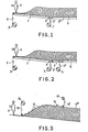
- FIG. 1 illustrates a traditional foaming installation of which the only basic ribbon has been considered.
- the installation comprises a first conveyor belt 1 slightly inclined downwards, on which, after the interposition of a flexible tape 2 coming from a roller 3, the reactive mixture formed is poured into a mixing head 4.
- the deposited mixture With the time and, consequently, with advancement on the conveyor belt 1 which is kept in continuous movement, the deposited mixture begins its reaction and its expansion, so that (the space being limited on the sides by ribbons not shown) the foam that forms rises from level until it reaches a maximum level; the foam material then becomes solid.
- the flexible ribbon 2 is formed by a coupler (FIGS. 7 and 8) comprising a ribbon 2 'of paper (which gives the coupler sufficient rigidity to ensure that the corresponding surface of the material in foam is flat and to allow proper handling of the flexible tape) and a very thin plastic tape 2 "(which gives the coupling a substantially complete impermeability).
- This plastic tape can advantageously be formed from polyethylene from 5 to 40 microns thick or, more preferably still, 10 to 20 microns thick.
- the point where the paper tape is detached from the polyethylene tape can be substantially the same where, in a traditional installation, the uncoupled paper tape would be detached, or it can even be a little closer to the mixing head 4 , in consideration of the fact that the detachment, in this case, does not include a peeling action of the bread and it can therefore be done in the presence of a consolidation condition which is even lower than that necessary to resist a peeling action.
- FIG. 2 which refers to the second example of application of the invention, shows parts identical to those of FIG. 1, indicated by the same references, but it illustrates how, at the final end of the conveyor belt 9 (which is continued by a subsequent conveyor 10) the polyethylene tape 2 "which had remained adherent to the bread 6 is also detached and it is collected on a roller 11. This is done downstream of the point of detachment of the paper tape 2 ' , at a point where the bread 6 has reached a consolidation such that it allows it to resist the peeling action inherent in the detachment of the polyethylene tape, action moreover very moderate in view of the waterproofing of this tape, which prevents any energetic adherence to bread.
- FIG. 3 shows, in relation to the mixing head 4 and the bread 6, the characteristic parts of an installation of the Hennecke type, that is to say a flexible tape 12, coming from a roller 13, which is guided by means of plates 17 along the upper surface of the material 6 expanding to beyond point 5 where the maximum level of the material is reached, after which it is removed on a roller 14, possibly after being perforated at 15.
- the ribbon 12 when applying the invention, the ribbon 12 must be a coupler of the same kind which has already been indicated, and in the roll 14 is collected the only ribbon 12 'of paper from the coupler 12, allowing the 12 "plastic tape adhered to the upper surface of the bread 6.
- Figure 4 shows how the installation according to Figure 3 must be modified when one wants to apply the invention in its second form.
- the 12 "polyethylene tape, which had remained adherent to the upper surface of the bread 6 is removed at a point located downstream from that where the paper tape 12 ′ collected on the roll 14 was removed, and, in turn, it is wound to form a roll 16.
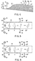
- FIG. 5 shows how the invention, in its first form, can find its application with regard to the side tapes in a foaming installation.
- the installation is illustrated in plan; the mixing head 4 pours the reactive mixture onto the flexible tape 2, which covers the basic conveyor belt and on which the mixture expands to form the bread 6.
- the foaming space is laterally limited by walls 22 and 23 , inside which the flexible ribbons 18 and 20 which come from the rollers 19 and 21 slide.
- these flexible ribbons are formed by a paper and thin plastic coupling, and the paper ribbons 18 'and 20' are removed, after consolidation of the foam, by separating them from the respective plastic ribbons 18 "and 20" which remain adherent to the side surfaces of the bread 6, while the paper ribbons 18 'and 20' are collected on rollers 24 and 25.
- the invention can be applied in its second form even with regard to the side tapes, as shown in FIG. 6.
- the plastic tapes 18 "and 20" which had remained adherent to the side surfaces of the bread 6 are removed, at points downstream from those where the paper ribbons 18 'and 20' have been collected on the rollers 24 and 25, and they are in turn wound up to form the rollers 26 and 27.
Landscapes
- Casting Or Compression Moulding Of Plastics Or The Like (AREA)
- Laminated Bodies (AREA)
- Manufacture Of Porous Articles, And Recovery And Treatment Of Waste Products (AREA)
- Processing And Handling Of Plastics And Other Materials For Molding In General (AREA)
- Adhesive Tapes (AREA)
Description
- La présente invention se réfère aux procédés de moussage en continu de matières plastiques, spécialement mais non exclusivement pour la production de blocs de mousse de polyuréthane et similaires.
- Dans ces procédés, le mélange de produits de départ, destinés à réagir et à se transformer en mousse, est versé sur un ruban de matériel flexible, leqùel avance sur un transporteur à bande, qui définit la base des blocs qu'on veut produire, et qui est replié verticalement pour définir aussi les flancs des mêmes blocs, ou bien il est accompagné par d'autres rubans séparés définissant ces flancs, et dans certains cas il est encore accompagné par un autre ruban qui définit la surface supérieure des blocs. Cex rubans délimitent l'espace dans lequel a lieu l'expansion de la mousse du mélange en réaction, et ils définissent donc la forme de la mousse solidifiée. Dès que la solidification est suffisante, on détache lesdits rubans flexibles du matériel qui avance encore en continu et on coupe ensuite le matériel en blocs des dimensions désirées, qui sont portés sur des étagères appropriées où les réactions en cours se complètent. Comme rubans flexibles pour le but indiqué on emploie normalement des rubans de papier. Bien que ce papier soit traité exprès pour limiter sa perméabilité, des quantités importantes du mélange versé sont absorbées par le papier et elles sont ensuite emportées avec le papier, avec le double inconvénient d'un gaspillage de matériel et d'une pollution du papier, qu'on ne peut récupérer même comme pâte de papeterie et qui pose par conséquent des problèmes d'élimination. Dans les cas où la bande du trasporteur est chauffée pour réduire l'épaisseur de la peau non moussée qui se forme à la base des blocs, la peau peut adhérer tellement au papier qu'elle se détache du bloc au moment où l'on détache le papier, ainsi produisant une autre forte perte de matériel. Dans certaines conditions il se vérifie même une transsudation de substances à travers le papier, avec un conséquent souillement des installations.
- Pour remédier à ces inconvénients on a tenté d'employer des rubans imperméables, par exemple de polyéthylène, au lieu du papier, mais les résultats ne semblent pas satisfaisants à cause de l'insuffisante rigidité des rubans; d'autre part, la récupération du matériel de ces rubans, indispensable en considération de leur prix de revient, pose des considérables problèmes techniques.
- On a aussi tenté de superposer, à un ruban de papier qui vient d'un rouleau, un ruban de polyéthylène relativement mince qui vient d'un autre rouleau, mais il n'est pas résulté possible, en conditions de gestion industrielle, d'assurer que le mince ruban de polyéthylène adhère en plan et sans froncis au ruban de papier malgré les contraintes qu'on doit appliquer pour produire l'avancement des rubans.
- Par la publication FR-E 95213 il est aussi connu de disposer, dans l'installation de moussage, des rouleaux de ruban de papier de support et des rouleaux de ruban de polyéthylène; de coupler entre eux ces deux rubans dans l'installation, par un adhésif déplaçable; de saisir le ruban de polyéthylène par des rouleaux de pincement et de le déplacer par rapport au ruban de papier contre l'action de l'adhésif; et enfin de renvider sur un rouleau le ruban de polyéthylène toujours accouplé avec le ruban de papier. Cette disposition atteint le but de déplacer les parois de l'espace de moussage pendant la croissance de la mousse, de sorte à obtenir une surface supérieure substantiellement plane de celle-ci. Toutefois la disposition n'est pas en condition de protéger entièrement le ruban de papier contre la pollution, ni d'empêcher entièrement la transsudation du mélange en réaction, car la partie inférieure des rubans de papier reste dépourvue de la protection assurée par le ruban de polyéthylène lors que celui-ci est déplacé par rapport au ruban de papier. D'autre côté les rubans de papier et de polyéthylène, renvidés à l'état accouplé, constituent une masse dont la récupération serait extrêmement difficile sinon impossible. Cela comporte une perte importante de matériel, car le ruban de polyéthylène doit présenter, dans ce cas, une épaisseur relativement élevée, d'un côté pour autoriser l'opération d'accouplement avec le ruban de papier sans l'emploi d'installations spéciales, et d'autre côté pour permettre aux rouleaux de pincement de déplacer le ruban de polyéthylène par rapport au ruban de papier, contre l'action de l'adhésif, sans le déchirer.
- Le but de la présente invention est de resoudre rationnellement le problème d'éliminer ou de limiter les susdits inconvénients qui se présentent dans la production en continu de mousses, et particulièrement d'empêcher le souillement du ruban de papier et la transsudation du mélange de réaction, et d'eliminer ou de limiter les pertes des matériaux constituant les ruban employés pour délimiter l'espace de moussage.
- Ce but est atteint, suivant l'invention, dans un procédé pour le moussage en continu de matières plastiques, du type dans lequel l'espace de moussage est limité par des rubans flexibles guidés de sorte à accompagner les surfaces correspondantes du matériel en cours d'expansion et de consolidation, et dans lequel chaque ruban flexible comprend un ruban de support de papier et un ruban de matière plastique, superposé audit ruban de papier du côté intérieur par rapport à l'espace de moussage et ayant une adhésion limitée par rapport audit ruban de papier, par le fait que comme ruban flexible on emploie un ruban accouplé, préparé et enroulé avant l'introduction dans l'installation de moussage; que ledit ruban flexible comprend un ruban de matière plastique d'une épaisseur comprise entre 5 et 20 microns; et qu'on détache le ruban de papier du matériel en mousse formé en le désaccouplant du ruban de matière plastique, en enroulant séparément ledit ruban de papier et en laissant ledit ruban de matière plastique au moins temporairement adhérent à la mousse.
- Grâce à cette façon de procéder, le ruban de matière plastique employé est extrêmement mince et donc économique; il protège la surface toute entière du ruban de papier, et donc on obtient une complète imperméabilité des rubans qui délimitent l'espace d'expansion et, par conséquent, le ruban de papier qui est détaché de la mousse formée n'emporte avec lui aucune trace de matériel en mousse ou de ses composants, en évitant ainsi systématiquement le gaspillage de ces matières et, en outre, en rendant possible la complète récupération du papier non pollué. Même dans le cas où le chauffage du ruban transporteur est poussé pour réduire au minimum l'épaisseur de la peau qui se forme à la base du pain de mousse, il n'y a aucun risque d'arrachement de cette peau quand on détache le ruban de papier. Aucune transsudation n'est possible, et on évite ainsi tout souillement de l'installation.
- Dans une première manière d'application de l'invention, le ruban de matière plastique très mince qui, à l'origine, était accouplé au ruban de papier, et duquel ce dernier a été détaché, est laissé adhérent aux surfaces correspondantes du bloc en mousse qui s'est formé, sans que cela entraîne, en général, aucun inconvénient. En effet, le ruban de matière plastique très mince sera en son temps emporté du bloc formé, en même temps que la couche de peau présentée par le bloc, laquelle doit être coupée et enlevée. Au contraire, dans une seconde manière d'application de l'invention, le ruban en matière plastique est détaché à son tour de la mousse formée, après le détachement du ruban de papier, et il est recueilli séparément de l'autre ruban et envoyé à la récupération.
- Le fait d'employer un ruban accouplé, dans lequel un ruban de papier agit comme support pour un ruban très mince de matière plastique, permet de limiter beaucoup la consommation de matière plastique, en vue de la possibilité de réduire au minimum, par exemple dans l'ordre du centième de millimètre, son épaisseur, tandis qu'un ruban d'une épaisseur tellement réduite, non accouplé à un ruban de papier, ne pourrait trouver aucun emploi dans une installation industrielle de moussage. L'adhésion entre les deux composants du ruban accouplé, bien que réduite, assure la planéité parfaite du ruban intérieur en matière plastique, sans rendre nécessaire aucune précaution particulière dans le traitement du ruban accouplé par rapport à un ruban ordinaire de papier. Le papier inclus dans l'accouplé peut être de qualité inférieure à celui qu'on emploie ordinairement, puisque on n'en exige de lui aucune imperméabilité, en consentant ainsi une réduction du prix de revient. La matière plastique incluse dans l'accouplé peut être choisie dans un vaste champ de possibilités et, particulièrement, elle peut être constituée par un économique polyéthylène auquel on ne demande pas de propriétés particulières. L'accouplé, comme tel, résulte en outre économique parce qu'on lui demande une basse adhésion entre les composants, tandis que la difficulté qu'on encontre généralement dans la production des accouplés,et est surmontée par des opérations qui en augmentent le prix de revient, est celle d'obtenir une plus forte adhésion entre les composants.
- Dans sa première forme de mise en oeuvre, qui prévoit de laisser le ruban de matière plastique adhérent à la mousse formée, l'invention peut trouver son application dans une installation ordinaire de moussage, sans en demander aucune modification ou adaptation, mais seulement la substitution des rouleaux de papier habituellement employés par des rouleaux similaires de ruban accouplé. Dans la seconde forme de mise en oeuvre, l'application de l'invention exige une adaptation des installations habituelles, avec doublement des moyens d'éloignement des rubans de la mousse formée, les premiers de ces moyens pourvoyant au détachement et au recueil du papier et les seconds pourvoyant séparément au détachement et recueil du ruban très mince de matière plastique.
- On pourrait aussi prévoir le détachement de l'accouplé sans séparer ses composants (dans ce cas l'exigence initiale d'employer un accouplé à basse adhésion n'existerait pas), mais cette manière de procéder résulte moins avantageuse car elle gêne gravement la successive récupération du papier et de la matière plastique ainsi restés accouplés.
- Ce qui a une grande importance pratique c'est le fait que l'invention est applicable sans difficultés aux installations de moussage de tous les différents genres existants. Elle peut concerner tous ou seulement une partie des rubans employés dans une installation; naturellement, le plus grand avantage est celui de l'application de l'invention au ruban inférieur sur lequel est versé le mélange réactif. L'invention peut donc être appliquée seulement au ruban replié en «U» formant la base et les flancs de l'espace de moussage, dans les installations à un seul ruban, ou bien elle peut être appliquée au seul ruban de base ou encore à ce ruban ainsi qu'aux rubans latéraux dans les installations à trois rubans; elle peut être appliquée au ruban supérieur destiné à rendre plane la surface superieure du bloc formé, dans les installations du type Hennecke et Planiblock; elle est compatible avec la présence des rubans latéraux en polyéthylène, déviés vers le haut, dans les installations du type Draka et Petzetakis, et elle peut trouver, naturellement, son application même dans les installations du type Maxfoam, quoique dans ces dernières le ruban de base ne reçoit pas directement le mélange réactif mais un matériel mousseux qui a déjà réagit partiellement.
- L'invention peut trouver son application soit dans la production de mousses flexibles que dans la production de mousses rigides, à cellules ouvertes ou closes et de caractéristiques différentes. Le domaine d'application principal est celui du moussage de composés polyuréthaniques mais, bien entendu, l'invention peut être appliquée au moussage d'autres matières synthétiques présentant des exigences similaires.
- Les particularités du procédé selon l'invention apparaîtront plus clairement de la suivante description de certains exemples d'application, faite avec référence au dessins schématiques annexés, dans lesquels:
- la figure 1 illustre le schéma d'une installation traditionnelle, dans laquelle l'invention est appliquée dans une première forme qui prévoit que le composant en matière plastique du ruban accouplé soit laissé adhérant aux blocs de mousse formés;
- la figure 2 illustre le schéma analogue dans le cas d'application de la seconde forme de l'invention, dans laquelle le composant en matière plastique du ruban accouplé est détaché lui aussi des blocs formés;
- la figure 3 montre comment l'invention, dans ce cas dans sa première forme, peut être appliquée au ruban supérieur dans un procédé du type Hennecke ou Planiblock;
- la figure 4 illustre l'application de l'invention, dans sa seconde forme, au ruban supérieur dans un procédé Hennecke ou Planiblock;
- la figure 5 montre en plan l'application de l'invention aux rubans latéraux d'une installation à trois rubans, dans la première forme de réalisation;
- la figure 6 montre de manière similaire l'application de la seconde forme de l'invention aux rubans latéraux d'une installation;
- la figure 7 montre un tronçon de ruban accouplé avec ses composants partiellement séparés;
- la figure 8 montre en très grande échelle une section du ruban accouplé; et
- la figure 9 montre en très grande échelle un bout de bloc formé en mousse solidifiée ayant un ruban de matière plastique adhérent à sa surface.
- Le schéma de la figure 1 illustre une installation traditionnelle de moussage de laquelle on a considéré le seul ruban de base. L'installation comprend un premier tapis transporteur 1 légèrement incliné vers le bas, sur lequel, après l'interposition d'un ruban flexible 2 venant d'un rouleau 3, on verse le mélange réactif formé dans une tête de mélange 4. Avec le temps et, par conséquent, avec l'avancement sur le tapis transportateur 1 qui est maintenu en mouvement continu, le mélange déposé commence sa réaction et son expansion, de sorte que (l'espace étant limité sur les côtés par des rubans non représentés) la mousse qui se forme monte de niveau jusqu'à atteindre en un niveau maximum; le matériel en mousse devient alors solide.
- Selon l'application de l'invention, le ruban flexible 2 est formé par un accouplé (figures 7 et 8) comprenant un ruban 2' de papier (qui donne à l'accouplé une rigidité suffisante pour assurer que la correspondante surface du matériel en mousse soit plane et pour permettre une manipulation appropriée du ruban flexible) et un ruban en matière plastique très mince 2" (qui donne à l'accouplé une imperméabilité substantiellement complète). Ce ruban en matière plastique peut être avantageusement formé de polyéthylène de 5 à 40 microns d'épaisseur ou, plus préférablement encore, de 10 à 20 microns d'épaisseur.
- Ces deux composants de l'accouplé sont unis l'un à l'autre de manière qu'ils présentent une adhésion réciproque limitée, suffisante pour éviter tout détachement pendant la manipulation du ruban accouplé et pendant son emploi pour limiter l'espace de moussage, mais telle à consentir facilement le détachement intentionnel des deux composants.
- Dans un point de l'installation, où le matériel en mousse 6 a déjà atteint un degré de consolidation tel qu'il n'a plus besoin ultérieurement du support rigide fourni par le ruban de papier qui fait partie du ruban accouplé 2, on détache ledit ruban de papier 2' du ruban de polyéthylène 2" avec lequel il était accouplé, et le ruban de papier 2" est recueilli sur un rouleau 7. Dans l'exemple représenté cela se fait en correspondance du rouleau 8 de renvoi final du ruban transporteur incliné 1. Sur un tapis transporteur successif 9 procède le matériel en mousse 6 qui forme une masse dite pain qui porte, comme revêtement superficiel, le ruban de polyéthylène 2" qui faisait partie de l'accouplé 2 (figure 9). Le pain 6 sera successivement coupé en blocs et laissé mûrir.
- Le point où le ruban de papier est détaché du ruban de polyéthylène peut être substantiellement le même où, dans une installation traditionnelle, on détacherait le ruban de papier non accouplé, ou bien il peut même être un peu plus près de la tête de mélange 4, en considération du fait que le détachement, dans ce cas, ne comporte pas une action de pelage du pain et il peut donc être fait en présence d'une condition de consolidation encore inférieure à celle nécessaire pour résister à une action de pelage.
- La figure 2, qui se réfère au second exemple d'application de l'invention, montre des parties identiques à celles de la figure 1, indiquées par les mêmes références, mais elle illustre comment, à l'extrémité finale du tapis transporteur 9 (qui est poursuivi par un ultérieur transporteur 10) le ruban de polyéthylène 2" qui était resté adhérent au pain 6 est détaché lui aussi et il est recueilli sur un rouleau 11. Cela est fait en aval du point de détachement du ruban de papier 2', en un point où le pain 6 a atteint une consolidation telle qui lui consent de résister à l'action de pelage inhérente au détachement du ruban de polyéthylène, action d'ailleurs très modérée en vue de l'imperméabilité de ce ruban, laquelle prévient toute adhésion énergique au pain.
- La figure 3 montre, en relation à la tête de mélange 4 et au pain 6, les parties caractéristiques d'une installation du type Hennecke, c'est à dire un ruban flexible 12, provenant d'un rouleau 13, qui est guidé au moyen de plaques 17 lelong de la surface supérieure du matériel 6 en expansion jusqu'au-delà du point 5 où le niveau maximum du matériel est atteint, après quoi il est retiré sur un rouleau 14, éventuellement après avoir été perforé en 15. Dans ce cas, quand on applique l'invention, le ruban 12 doit être un accouplé du même genre qui a été déjà indiqué, et dans le rouleau 14 est recueilli le seul ruban 12' de papier de l'accouplé 12, en laissant procéder le ruban de matière plastique 12" adhérent à la surface supérieure du pain 6.
- La figure 4 montre comment l'installation selon la figure 3 doit être modifiée quand on veut appliquer l'invention dans sa seconde forme. Dans ce cas, même le ruban de polyéthylène 12", qui était resté adhérent à la surface supérieure du pain 6, est retiré en un point situé en aval de celui où a été retiré le ruban de papier 12' recueilli sur le rouleau 14, et, à son tour, il est enroulé pour former un rouleau 16.
- La figure 5 montre comment l'invention, dans sa première forme, peut trouver son application pour ce qui concerne les rubans latéraux dans une installation de moussage. Dans le schéma de la figure 5 l'installation est illustrée en plan; la tête de mélange 4 verse le mélange réactif sur le ruban flexible 2, qui recouvre le tapis transporteur de base et sur lequel le mélange fait son expansion pour former le pain 6. L'espace de moussage est limité latéralement par des parois 22 et 23, à l'intérieur desquelles glissent les rubans flexibles 18 et 20 qui viennent des rouleaux 19 et 21. En application de l'invention, ces ruban flexibles sont formés par un accouplé de papier et de matière plastique mince, et les rubans de papier 18' et 20' sont retirés, après la consolidation de la mousse, en les séparant des respectifs rubans de matière plastique 18" et 20" qui restent adhérents aux surfaces latérales du pain 6, tandis que les rubans de papier 18' et 20' sont recueillis sur les rouleaux 24 et 25.
- L'invention peut être appliquée dans sa seconde forme même pour ce qui concerne les rubans latéraux, comme le montre la figure 6. Dans ce cas, les rubans de matière plastique 18" et 20" qui étaient restés adhérents aux surfaces latérales du pain 6 sont retirés, en des points en aval de ceux où les rubans de papier 18' et 20' ont été recueillis sur les rouleaux 24 et 25, et il sont à leur tour enroulés pour former les rouleaux 26 et 27.
- Même si, dans la description qui précède, l'application de l'invention dans ses différentes formes a été décrite séparément pour le ruban de base, pour le ruban supérieur et pour les rubans latéraux, il faut bien entendre que les différentes dispositions décrites et illustrées peuvent coexister, c'est à dire que, dans une installation réelle avec plusieurs rubans flexibles, l'invention peut être appliquée à tous les rubans ou bien a une partie ou même à un seul d'entre eux, selon l'opportunité opérative chaque fois constatée.
Claims (3)
Priority Applications (1)
| Application Number | Priority Date | Filing Date | Title |
|---|---|---|---|
| AT83200002T ATE19369T1 (de) | 1982-01-18 | 1983-01-04 | Verfahren zum kontinuierlichen aufschaeumen von kunststoffen. |
Applications Claiming Priority (2)
| Application Number | Priority Date | Filing Date | Title |
|---|---|---|---|
| IT6704682 | 1982-01-18 | ||
| IT67046/82A IT1155453B (it) | 1982-01-18 | 1982-01-18 | Procedimento ed impianto per la schiumatura in continuo di materie plastiche e prodotti che ne risultano |
Publications (2)
| Publication Number | Publication Date |
|---|---|
| EP0084384A1 EP0084384A1 (fr) | 1983-07-27 |
| EP0084384B1 true EP0084384B1 (fr) | 1986-04-23 |
Family
ID=11299155
Family Applications (1)
| Application Number | Title | Priority Date | Filing Date |
|---|---|---|---|
| EP83200002A Expired EP0084384B1 (fr) | 1982-01-18 | 1983-01-04 | Procédé pour le moussage en continu de matières plastiques |
Country Status (6)
| Country | Link |
|---|---|
| US (1) | US4492664A (fr) |
| EP (1) | EP0084384B1 (fr) |
| AT (1) | ATE19369T1 (fr) |
| DE (1) | DE3363106D1 (fr) |
| ES (1) | ES8406941A1 (fr) |
| IT (1) | IT1155453B (fr) |
Families Citing this family (19)
| Publication number | Priority date | Publication date | Assignee | Title |
|---|---|---|---|---|
| DE3707400C1 (de) * | 1987-03-07 | 1988-03-10 | Kulzer & Co Gmbh | Form zum Einbetten von histologischen Praeparaten |
| GB9014331D0 (en) * | 1990-06-27 | 1990-08-15 | Bareuter Gerd | Manufacture of polymeric foam |
| US5665287A (en) * | 1993-07-14 | 1997-09-09 | Foaming Technologies Cardio Bv | Froth process for continous manufacture of polyurethane foam slab-stocks |
| IT1270979B (it) * | 1993-09-30 | 1997-05-26 | Afros Spa | Procedimento e apparecchiatura per la produzione in continuo di schiume poliuretaniche in blocchi |
| NO309077B1 (no) | 1993-07-14 | 2000-12-11 | Foaming Techn Cardio Bv | FremgangsmÕte og system for kontinuerlig tilvirkning av polyuretanskumblokker |
| DE102004059724A1 (de) | 2004-12-11 | 2006-06-14 | Bayer Materialscience Ag | Verfahren und Anlage zur Herstellung von Schaumstoff in einem kontinuierlichen Schaumprozess |
| DE102005003341A1 (de) | 2005-01-25 | 2006-07-27 | Bayer Materialscience Ag | Verfahren und Anlage zur optimierten Herstellung von Schaumstoff in einem kontinuierlichen Blockschaumprozess |
| US8752348B2 (en) * | 2005-02-25 | 2014-06-17 | Syntheon Inc. | Composite pre-formed construction articles |
| BRPI0607377A2 (pt) * | 2005-02-25 | 2010-03-23 | Nova Chem Inc | composiÇço de cimento de baixo peso, leito de estrada, artigo de construÇço painel compàsito, estrutura de concreto isolada, mÉtodo de fabricar um artigo de composiÇço de cimento de baixo peso, artigo de concreto de baixo peso e unidade estrutural de baixo peso |
| CA2598442C (fr) * | 2005-02-25 | 2011-02-08 | Nova Chemicals Inc. | Panneaux de construction preformes composites |
| JP2008534418A (ja) | 2005-03-22 | 2008-08-28 | ノバ・ケミカルズ・インコーポレイテツド | 軽量コンクリート組成物 |
| US7741266B2 (en) * | 2005-06-20 | 2010-06-22 | Rotuba Extruders, Inc. | Process for preparing scented cellulosics and products prepared thereby |
| US20070187516A1 (en) * | 2005-06-20 | 2007-08-16 | Rotuba Extruders, Inc. | Scented authorization card and method of manufacture |
| US7677009B2 (en) * | 2007-02-02 | 2010-03-16 | Nova Chemicals Inc. | Roof truss system |
| US8048219B2 (en) * | 2007-09-20 | 2011-11-01 | Nova Chemicals Inc. | Method of placing concrete |
| US20090078161A1 (en) * | 2007-09-20 | 2009-03-26 | Nova Chemicals Inc. | Methods of minimizing concrete cracking and shrinkage |
| PL235291B1 (pl) | 2013-09-16 | 2020-06-15 | Labanowicz Sebastian | Sposób wytwarzania materacy piankowych z wtopionymi sprężynami |
| PL3015239T3 (pl) | 2014-11-03 | 2021-11-08 | Mondi Ag | Zdzieralna, elastyczna i przezroczysta okładzina procesowa |
| DE102024126818A1 (de) * | 2024-09-17 | 2026-03-19 | Hennecke Gmbh | Verfahren und Vorrichtung zum kontinuierlichen Herstellen eines Stranges aus Reaktivkunststoff |
Family Cites Families (10)
| Publication number | Priority date | Publication date | Assignee | Title |
|---|---|---|---|---|
| FR95213E (fr) * | 1965-11-12 | 1970-08-07 | Hellenic Plastics Rubber | Procédé et dispositif de production de mousse de polyuréthane. |
| US3812227A (en) * | 1967-04-12 | 1974-05-21 | J Blackwell | Method of producing a flat top slab of foamed polyurethane |
| NL170928C (nl) * | 1971-05-11 | 1983-01-17 | Hennecke Gmbh Maschf | Inrichting voor het continu vervaardigen van eindloze schuimkunststofblokken. |
| GB1564604A (en) * | 1975-11-07 | 1980-04-10 | Unifoam Ag | Manufacture of polymeric foam |
| US3906068A (en) * | 1973-12-13 | 1975-09-16 | Textron Inc | Process for continuously producing foamed material of rectangular shape |
| GB1487848A (en) * | 1974-02-20 | 1977-10-05 | Planiblock Sa | Apparatus for the continuous manufacture of foamed plastics blocks |
| DE2449107C3 (de) * | 1974-10-15 | 1980-10-16 | Metzeler Schaum Gmbh, 8940 Memmingen | Verfahren zur kontinuierlichen Herstellung von Schaumstoffblöcken mit rechteckigem Querschnitt |
| US4154562A (en) * | 1977-08-31 | 1979-05-15 | Kornylak Corporation | Adjustable width molding apparatus for a flat-top bun |
| DE2813137C3 (de) * | 1978-03-25 | 1980-10-16 | Metzeler Schaum Gmbh, 8940 Memmingen | Vorrichtung zur Synchronisierung der Bewegungen der Abdeckbahn und der Bodenbahn bei der Herstellung von Schaumstoffblöcken |
| US4343164A (en) * | 1980-07-11 | 1982-08-10 | Presto Lock, Inc. | Combination locks |
-
1982
- 1982-01-18 IT IT67046/82A patent/IT1155453B/it active
-
1983
- 1983-01-04 DE DE8383200002T patent/DE3363106D1/de not_active Expired
- 1983-01-04 AT AT83200002T patent/ATE19369T1/de not_active IP Right Cessation
- 1983-01-04 US US06/455,580 patent/US4492664A/en not_active Expired - Lifetime
- 1983-01-04 EP EP83200002A patent/EP0084384B1/fr not_active Expired
- 1983-01-14 ES ES519002A patent/ES8406941A1/es not_active Expired
Also Published As
| Publication number | Publication date |
|---|---|
| IT1155453B (it) | 1987-01-28 |
| DE3363106D1 (en) | 1986-05-28 |
| US4492664A (en) | 1985-01-08 |
| ATE19369T1 (de) | 1986-05-15 |
| EP0084384A1 (fr) | 1983-07-27 |
| ES519002A0 (es) | 1984-08-16 |
| ES8406941A1 (es) | 1984-08-16 |
| IT8267046A0 (it) | 1982-01-18 |
Similar Documents
| Publication | Publication Date | Title |
|---|---|---|
| EP0084384B1 (fr) | Procédé pour le moussage en continu de matières plastiques | |
| EP0151088A2 (fr) | Procédé de préparation d'un matériau sandwich à ondulations intérieures de papier et protection extérieure par pellicule plastique. | |
| EP0135431A1 (fr) | Procédé de fabrication d'opercules pour récipients à ouverture par pelage et opercules obtenus par la mise en oeuvre de ce procédé | |
| BE898071A (fr) | Couche pour bebe a jeter. | |
| EP1523517B1 (fr) | Mousse avec une bande de matière adhésive | |
| WO1991016870A1 (fr) | Procede de fabrication en continu d'articles d'hygiene tels que des couches-culottes, et article d'hygiene ainsi fabrique | |
| CH365276A (fr) | Matériel d'emballage muni d'un ruban d'arrachage et procédé de fabrication de ce matériel | |
| CA2179173A1 (fr) | Article, notamment plaque de revetement de batiments, et procede de fabrication d'un tel article | |
| CH616366A5 (fr) | ||
| FR2497725A1 (fr) | Panneau enduit pour confectionner des moules et des coffrages a beton, et procede pour la fabrication de ce panneau | |
| EP0775045A1 (fr) | Procede de fabrication d'un article en forme de plaque et article fabrique | |
| EP0412867B1 (fr) | Procédé de traitement antiadhérent en continu d'un cordon de matière adhésive permanente plus particulièrement d'un adhésif thermofusible à la sortie d'un mélangeur extrudeur ainsi qu'installation permettant la mise en oeuvre de ce procédé et produit ainsi obtenu | |
| EP0780213A1 (fr) | Procédé de fabrication d'une pièce en matériau composite par moulage par transfert de résine, et pièce obtenue par ce procédé | |
| FR2498981A1 (fr) | Filiere pour la production de pellicules par extrusion | |
| EP1997977B1 (fr) | Panneau préfabriqué pour le revêtement mural de bâtiment | |
| BE1026867B1 (fr) | Matériau multicouche de protection de câble pour hautes températures | |
| CA2161124C (fr) | Procede de traitement anti-adherent en continu d'un adhesif thermofusible collant en surface | |
| EP1601581B1 (fr) | Recipient pour produits salissants | |
| EP1884268A1 (fr) | Procédé de fabrication d'une planche de glisse | |
| FR2461070A1 (fr) | Element isolant en forme de plaque et procede de fabrication d'un tel element | |
| FR2480669A1 (fr) | Procede et dispositif pour la fabrication de feuilles de matiere plastique de haute qualite optique et produits obtenus | |
| FR2614233A1 (fr) | Procede de realisation d'une feuille de matiere plastique a plusieurs couches dont une couche d'adhesif et procede de realisation d'un corps en nappe a l'aide d'une telle feuille; feuille et corps en nappe ainsi obtenus. | |
| FR3120006A1 (fr) | Procede de fabrication de packs secables | |
| FR2755115A1 (fr) | Dispositif de transfert et d'extraction, par rapport a un poste de travail, d'un flan de matiere collante et presse de transformation en faisant application | |
| FR2487254A1 (fr) | Structure de papier renforce par des fils metalliques |
Legal Events
| Date | Code | Title | Description |
|---|---|---|---|
| PUAI | Public reference made under article 153(3) epc to a published international application that has entered the european phase |
Free format text: ORIGINAL CODE: 0009012 |
|
| AK | Designated contracting states |
Designated state(s): AT BE CH DE FR GB LI NL SE |
|
| 17P | Request for examination filed |
Effective date: 19830915 |
|
| GRAA | (expected) grant |
Free format text: ORIGINAL CODE: 0009210 |
|
| AK | Designated contracting states |
Kind code of ref document: B1 Designated state(s): AT BE CH DE FR GB LI NL SE |
|
| REF | Corresponds to: |
Ref document number: 19369 Country of ref document: AT Date of ref document: 19860515 Kind code of ref document: T |
|
| REF | Corresponds to: |
Ref document number: 3363106 Country of ref document: DE Date of ref document: 19860528 |
|
| PLBI | Opposition filed |
Free format text: ORIGINAL CODE: 0009260 |
|
| 26 | Opposition filed |
Opponent name: JOST & BRAITSCH OHG Effective date: 19870114 |
|
| NLR1 | Nl: opposition has been filed with the epo |
Opponent name: JOST & BRAITSCH OHG |
|
| PLBM | Termination of opposition procedure: date of legal effect published |
Free format text: ORIGINAL CODE: 0009276 |
|
| STAA | Information on the status of an ep patent application or granted ep patent |
Free format text: STATUS: OPPOSITION PROCEDURE CLOSED |
|
| 27C | Opposition proceedings terminated |
Effective date: 19881008 |
|
| REG | Reference to a national code |
Ref country code: GB Ref legal event code: 746 Effective date: 19930224 |
|
| REG | Reference to a national code |
Ref country code: FR Ref legal event code: DL |
|
| PGFP | Annual fee paid to national office [announced via postgrant information from national office to epo] |
Ref country code: AT Payment date: 19931217 Year of fee payment: 12 |
|
| NLR2 | Nl: decision of opposition | ||
| PG25 | Lapsed in a contracting state [announced via postgrant information from national office to epo] |
Ref country code: AT Effective date: 19950104 |
|
| EAL | Se: european patent in force in sweden |
Ref document number: 83200002.0 |
|
| PGFP | Annual fee paid to national office [announced via postgrant information from national office to epo] |
Ref country code: GB Payment date: 19961224 Year of fee payment: 15 |
|
| PGFP | Annual fee paid to national office [announced via postgrant information from national office to epo] |
Ref country code: NL Payment date: 19970130 Year of fee payment: 15 |
|
| PGFP | Annual fee paid to national office [announced via postgrant information from national office to epo] |
Ref country code: BE Payment date: 19970228 Year of fee payment: 15 |
|
| PGFP | Annual fee paid to national office [announced via postgrant information from national office to epo] |
Ref country code: DE Payment date: 19970401 Year of fee payment: 15 |
|
| PG25 | Lapsed in a contracting state [announced via postgrant information from national office to epo] |
Ref country code: GB Free format text: LAPSE BECAUSE OF NON-PAYMENT OF DUE FEES Effective date: 19980104 |
|
| PGFP | Annual fee paid to national office [announced via postgrant information from national office to epo] |
Ref country code: SE Payment date: 19980127 Year of fee payment: 16 |
|
| PGFP | Annual fee paid to national office [announced via postgrant information from national office to epo] |
Ref country code: FR Payment date: 19980129 Year of fee payment: 16 |
|
| PG25 | Lapsed in a contracting state [announced via postgrant information from national office to epo] |
Ref country code: BE Free format text: LAPSE BECAUSE OF NON-PAYMENT OF DUE FEES Effective date: 19980131 |
|
| PGFP | Annual fee paid to national office [announced via postgrant information from national office to epo] |
Ref country code: CH Payment date: 19980327 Year of fee payment: 16 |
|
| BERE | Be: lapsed |
Owner name: S.P.A. GIUSEPPE OLMO SUPERDLEXITE ITALIANA Effective date: 19980131 |
|
| PG25 | Lapsed in a contracting state [announced via postgrant information from national office to epo] |
Ref country code: NL Free format text: LAPSE BECAUSE OF NON-PAYMENT OF DUE FEES Effective date: 19980801 |
|
| GBPC | Gb: european patent ceased through non-payment of renewal fee |
Effective date: 19980104 |
|
| NLV4 | Nl: lapsed or anulled due to non-payment of the annual fee |
Effective date: 19980801 |
|
| PG25 | Lapsed in a contracting state [announced via postgrant information from national office to epo] |
Ref country code: DE Free format text: LAPSE BECAUSE OF NON-PAYMENT OF DUE FEES Effective date: 19981001 |
|
| PG25 | Lapsed in a contracting state [announced via postgrant information from national office to epo] |
Ref country code: SE Free format text: LAPSE BECAUSE OF NON-PAYMENT OF DUE FEES Effective date: 19990105 |
|
| PG25 | Lapsed in a contracting state [announced via postgrant information from national office to epo] |
Ref country code: LI Free format text: LAPSE BECAUSE OF NON-PAYMENT OF DUE FEES Effective date: 19990131 Ref country code: CH Free format text: LAPSE BECAUSE OF NON-PAYMENT OF DUE FEES Effective date: 19990131 |
|
| REG | Reference to a national code |
Ref country code: CH Ref legal event code: PL |
|
| PG25 | Lapsed in a contracting state [announced via postgrant information from national office to epo] |
Ref country code: FR Free format text: LAPSE BECAUSE OF NON-PAYMENT OF DUE FEES Effective date: 19990930 |
|
| REG | Reference to a national code |
Ref country code: FR Ref legal event code: ST |