EP0084420A2 - Antenne, besonders zum Empfang von Übertragungssatelliten - Google Patents
Antenne, besonders zum Empfang von Übertragungssatelliten Download PDFInfo
- Publication number
- EP0084420A2 EP0084420A2 EP83300106A EP83300106A EP0084420A2 EP 0084420 A2 EP0084420 A2 EP 0084420A2 EP 83300106 A EP83300106 A EP 83300106A EP 83300106 A EP83300106 A EP 83300106A EP 0084420 A2 EP0084420 A2 EP 0084420A2
- Authority
- EP
- European Patent Office
- Prior art keywords
- reflector
- antenna
- sub
- antenna according
- main reflector
- Prior art date
- Legal status (The legal status is an assumption and is not a legal conclusion. Google has not performed a legal analysis and makes no representation as to the accuracy of the status listed.)
- Withdrawn
Links
Images


Classifications
-
- H—ELECTRICITY
- H01—ELECTRIC ELEMENTS
- H01Q—ANTENNAS, i.e. RADIO AERIALS
- H01Q15/00—Devices for reflection, refraction, diffraction or polarisation of waves radiated from an antenna, e.g. quasi-optical devices
- H01Q15/14—Reflecting surfaces; Equivalent structures
- H01Q15/141—Apparatus or processes specially adapted for manufacturing reflecting surfaces
-
- H—ELECTRICITY
- H01—ELECTRIC ELEMENTS
- H01Q—ANTENNAS, i.e. RADIO AERIALS
- H01Q19/00—Combinations of primary active antenna elements and units with secondary devices, e.g. with quasi-optical devices, for giving the antenna a desired directional characteristic
- H01Q19/10—Combinations of primary active antenna elements and units with secondary devices, e.g. with quasi-optical devices, for giving the antenna a desired directional characteristic using reflecting surfaces
- H01Q19/18—Combinations of primary active antenna elements and units with secondary devices, e.g. with quasi-optical devices, for giving the antenna a desired directional characteristic using reflecting surfaces having two or more spaced reflecting surfaces
- H01Q19/19—Combinations of primary active antenna elements and units with secondary devices, e.g. with quasi-optical devices, for giving the antenna a desired directional characteristic using reflecting surfaces having two or more spaced reflecting surfaces comprising one main concave reflecting surface associated with an auxiliary reflecting surface
Definitions
- This invention relates to an antenna, particularly a groundstation antenna for the reception of satellite broadcast television, business satellite communications or marine satellite communications.
- New television (TV) services based upon the direct broadcast of signals from geostationary satellites are planned. These will become available in several countries in the next few years. Such services will be received, in a domestic context, either by a satellite groundstation devoted to a single home or, alternatively, by a community groundstation and then relayed to a number of homes.
- the patent application describes the design of a microwave antenna which is suitable for incorporation in a domestic groundstation system.
- Antennae suitable for satellite broadcast reception fall into two categories, namely reflector antennae and planar array antennae.
- Reflector antennae are designed either with or without subreflectors, ie Cassegrain or front-fed respectively.
- the feed and/or sub-reflector(s) may be either along the principal axis of the main reflector (symmetrical) or offset.
- the simplest reflector antenna configuration a focal front-fed arrangement, generally requires a waveguide or coaxial cable to be routed from the microwave feed to a receiver. This implies a high radio frequency signal loss which is highly undesirable for satellite broadcast reception. Designs have been proposed where the receiver is suspended at the reflector focus; however the additional volume at the focus causes increased antenna aperture blockage (leading to lower efficiency, high sidelobes and depolarisation) and mechanical problems.
- the Cassegrain configuration overcomes the signal loss problem but requires an extra reflecting surface(s) (sub-reflector(s)) and possesses a greater number of degrees of mechanical freedom, which makes alignment problematical.
- an antenna comprises a main reflector having a parabolic reflecting surface, a sub-reflector having a hyperbolic reflecting surface and a microwave feed system aligned along the axis of the main reflector, wherein the two reflecting surfaces are accurately, permanently and non-adjustably located one with respect to the other and the two reflecting surfaces are protected from the environment surrounding the antenna.
- the main reflector and the sub-reflector are formed by an integral body which is conveniently of a foamed synthetic plastics material.
- the body may be moulded or cast in the desired shape, and have metal coatings over the parabolic and hyperbolic surfaces.
- the metal coatings may be deposited on the foamed body by spraying.
- a mounting flange is preferably attached to the parabolic surface by a suitable adhesive.
- the sub-reflector is integral with its radome support.
- the latter consists of a conical tube of a microwave transparent material, such as a plastics material, that extends from its base at the perimeter of the main reflector to the sub-reflector.
- the cone is truncated in the vicinity of the main reflector's primary focus and the truncating section formed by a hyperbolic surface.
- the inner surface of the hyperbola is coated with conducting material to form the sub-reflector.
- a simple bayonet or snap fastener arrangement may join the main reflector to the sub- reflector/radome allowing simple assembly and servicing.
- the main reflector has a diameter of typically 0.5 to 1.0 metres for 12 GHz TV direct broadcast, while suitable dimensions for the sub-reflector diameter and the distance from the feed to the sub-reflector are given in texts on antenna practice and theory, respectively.
- the fastening between the main reflector and combined radome/sub-reflector should be as waterproof as practically possible to reduce deterioration of the metallic surfaces by exposure to moisture.
- the surface of either the main reflector or the sub-reflector, or both can be modified to correct for any error caused by the presence of the radome material.
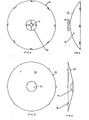
- the antenna of Figures 1 and 2 comprises a body 1 of foamed plastics material having a metallised hyperbolic surface 2 (forming a main reflector) and a metallised parabolic surface 3.
- the body 1 has a circular outer periphery marking the transition between the rear parabolic surface 3 and the front frusto-conical surface, in the centre of which is the hyperbolic surface 2.
- the metallised surfaces 2 and 3 are formed by deposition of metal on appropriate regions of the external surface of the body 1.
- the body 1 is moulded with a recess 4 to receive a feed horn carried by a mounting flange 5 which is attached to the body 1 by a suitable adhesive.
- the foamed body 1 is simple and cheap to mould or cast in the desired shape and is light yet robust. It will be appreciated that the body 1 may be made of any shape which presents the required parabolic and hyperbolic surfaces. In particular the external surface of the body surrounding the hyperbolic surface 2 may be shaped differently from the frusto-conical configuration shown.
- the metallised surfaces 2 and 3 are, where they reflect an incoming signal (e.g. along the single ray path A), covered by the foam meterial and therefore protected from the environment. Also, the surfaces 2 and 3 are maintained in their relative positions by virtue of being deposited on the common body 1 of foamed material.
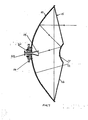
- the antenna of the second embodiment has a main reflector 10 which is of metal and plastics with a parabolic reflecting surface 12 having at its centre an orifice 13 surrounded by an antenna mounting flange 14.
- the sub-reflector 15 ( Figures 5 and 6) has a central hyperbolic reflecting surface 17 integral with and surrounded by a radome 16.
- the reflecting surfaces 12 and 17 are suitably formed by coating the concave side of the main reflector 10 and the convex side of the sub-reflector 15.
- Figure 7 shows the main reflector 10 and the sub-reflector 15 assembled together by means of a bayonet attachment around their peripheries, projections on the periphery of the sub-reflector engaging within slots in the periphery of the main reflector.
- the main reflector 10 and the sub-reflector 15 are in the nature of dished casing members so that the assembled antenna is a hollow shell-like structure which encloses the reflecting surfaces 12 and 17.
- the orifice 13 accommodates a feed horn 19 which has a feed output flange 20 and which is clamped in position by a detachable split feed clamp 21.
- the sub-reflector is in effect rigidly positioned and located with respect to the main reflector which is shaped to provide a convenient means of aligning a feed horn.
- the antenna of each embodiment is designed so that the reflecting surfaces are well protected, and so that the antenna is adaptable to accept future commercially available microwave feeds.
Landscapes
- Engineering & Computer Science (AREA)
- Manufacturing & Machinery (AREA)
- Physics & Mathematics (AREA)
- Electromagnetism (AREA)
- Aerials With Secondary Devices (AREA)
Applications Claiming Priority (4)
| Application Number | Priority Date | Filing Date | Title |
|---|---|---|---|
| GB8201417 | 1982-01-19 | ||
| GB8201417 | 1982-01-19 | ||
| GB8203068 | 1982-02-03 | ||
| GB8203068 | 1982-02-03 |
Publications (2)
| Publication Number | Publication Date |
|---|---|
| EP0084420A2 true EP0084420A2 (de) | 1983-07-27 |
| EP0084420A3 EP0084420A3 (de) | 1983-08-03 |
Family
ID=26281750
Family Applications (1)
| Application Number | Title | Priority Date | Filing Date |
|---|---|---|---|
| EP83300106A Withdrawn EP0084420A3 (de) | 1982-01-19 | 1983-01-10 | Antenne, besonders zum Empfang von Übertragungssatelliten |
Country Status (1)
| Country | Link |
|---|---|
| EP (1) | EP0084420A3 (de) |
Cited By (10)
| Publication number | Priority date | Publication date | Assignee | Title |
|---|---|---|---|---|
| EP0108515A1 (de) * | 1982-10-11 | 1984-05-16 | Cambridge Electronic Industries plc | Parabolspiegelantenne |
| EP0170726A1 (de) * | 1984-07-13 | 1986-02-12 | Siemens Aktiengesellschaft | Zweireflektor-Richtantenne |
| US4581615A (en) * | 1983-02-08 | 1986-04-08 | Levy Stanley P | Double reflector antenna with integral radome reflector support |
| GB2168854A (en) * | 1984-12-17 | 1986-06-25 | Shamah M | Antenna systems |
| US4977407A (en) * | 1981-07-23 | 1990-12-11 | Crane Patrick E | Optical collimator |
| GB2221351B (en) * | 1988-07-27 | 1991-12-04 | British Telecomm | Antenna |
| US5351060A (en) * | 1991-02-25 | 1994-09-27 | Bayne Gerald A | Antenna |
| EP2510576A4 (de) * | 2009-12-11 | 2014-05-14 | Andrew Llc | Bandklemme zur anbringung an einem reflektorantennenradom |
| WO2017152988A1 (en) * | 2016-03-10 | 2017-09-14 | Telefonaktiebolaget Lm Ericsson (Publ) | A reflector antenna arrangement |
| CN112635965A (zh) * | 2020-12-31 | 2021-04-09 | 西安恒达微波技术开发有限公司 | 一种应用于leo低轨卫星通信的双圆极化卡塞格伦天线 |
Family Cites Families (6)
| Publication number | Priority date | Publication date | Assignee | Title |
|---|---|---|---|---|
| US3374482A (en) * | 1958-09-30 | 1968-03-19 | Navy Usa | Radar dish in plastic casement |
| US3296685A (en) * | 1962-05-31 | 1967-01-10 | Sylvania Electric Prod | Method of making dielectric foam antenna |
| US3430244A (en) * | 1964-11-25 | 1969-02-25 | Radiation Inc | Reflector antennas |
| GB1100391A (en) * | 1965-01-12 | 1968-01-24 | Malifaud Pierre | Receivers for directional waves |
| GB1531242A (en) * | 1975-01-21 | 1978-11-08 | Post Office | Splash plate feed assemblies for aerials |
| DE2842298A1 (de) * | 1978-09-28 | 1980-05-22 | Siemens Ag | Richtantenne fuer sehr kurze elektromagnetische wellen |
-
1983
- 1983-01-10 EP EP83300106A patent/EP0084420A3/de not_active Withdrawn
Cited By (13)
| Publication number | Priority date | Publication date | Assignee | Title |
|---|---|---|---|---|
| US4977407A (en) * | 1981-07-23 | 1990-12-11 | Crane Patrick E | Optical collimator |
| EP0108515A1 (de) * | 1982-10-11 | 1984-05-16 | Cambridge Electronic Industries plc | Parabolspiegelantenne |
| US4581615A (en) * | 1983-02-08 | 1986-04-08 | Levy Stanley P | Double reflector antenna with integral radome reflector support |
| EP0170726A1 (de) * | 1984-07-13 | 1986-02-12 | Siemens Aktiengesellschaft | Zweireflektor-Richtantenne |
| GB2168854A (en) * | 1984-12-17 | 1986-06-25 | Shamah M | Antenna systems |
| GB2168854B (en) * | 1984-12-17 | 1989-06-14 | Shamah M | Antenna systems |
| GB2221351B (en) * | 1988-07-27 | 1991-12-04 | British Telecomm | Antenna |
| US5351060A (en) * | 1991-02-25 | 1994-09-27 | Bayne Gerald A | Antenna |
| EP2510576A4 (de) * | 2009-12-11 | 2014-05-14 | Andrew Llc | Bandklemme zur anbringung an einem reflektorantennenradom |
| WO2017152988A1 (en) * | 2016-03-10 | 2017-09-14 | Telefonaktiebolaget Lm Ericsson (Publ) | A reflector antenna arrangement |
| US10263343B2 (en) | 2016-03-10 | 2019-04-16 | Telefonaktiebolaget Lm Ericsson (Publ) | Reflector antenna arrangement |
| CN112635965A (zh) * | 2020-12-31 | 2021-04-09 | 西安恒达微波技术开发有限公司 | 一种应用于leo低轨卫星通信的双圆极化卡塞格伦天线 |
| CN112635965B (zh) * | 2020-12-31 | 2025-06-13 | 西安恒达微波技术开发有限公司 | 一种应用于leo低轨卫星通信的双圆极化卡塞格伦天线 |
Also Published As
| Publication number | Publication date |
|---|---|
| EP0084420A3 (de) | 1983-08-03 |
Similar Documents
| Publication | Publication Date | Title |
|---|---|---|
| US5117240A (en) | Multimode dielectric-loaded double-flare antenna | |
| US6512485B2 (en) | Multi-band antenna for bundled broadband satellite internet access and DBS television service | |
| US8497810B2 (en) | Multi-band antenna system for satellite communications | |
| US5309167A (en) | Multifocal receiving antenna with a single aiming direction for several satellites | |
| US5606334A (en) | Integrated antenna for satellite and terrestrial broadcast reception | |
| US7466282B2 (en) | Tri-head KaKuKa feed for single-offset dish antenna | |
| EP0084420A2 (de) | Antenne, besonders zum Empfang von Übertragungssatelliten | |
| US6535176B2 (en) | Multi-feed reflector antenna | |
| US7982687B1 (en) | Ka/Ku outdoor unit configuration using a frequency selective surface | |
| US6166704A (en) | Dual elliptical corrugated feed horn for a receiving antenna | |
| CN115315848B (zh) | 反射器天线重新指向设备和反射器天线 | |
| JPH02228103A (ja) | 円錐形ホーンアンテナ | |
| US7038632B2 (en) | Co-located multi-band antenna | |
| US6225964B1 (en) | Dual gridded reflector antenna system | |
| US6980170B2 (en) | Co-located antenna design | |
| EP0452077A1 (de) | Antennenanordnung | |
| US20020008669A1 (en) | Reflective antenna system with increased focal length | |
| WO1990006004A1 (en) | Offset parabolic reflector antenna | |
| KR200212460Y1 (ko) | 위성방송 수신용 엘엔비 고정브라켓 | |
| US20080120653A1 (en) | Method and apparatus for receiving dual band signals from an orbital location using an outdoor unit with a subreflector and additional antenna feed | |
| AU627720B2 (en) | Multimode dielectric-loaded multi-flare antenna | |
| CN112635965A (zh) | 一种应用于leo低轨卫星通信的双圆极化卡塞格伦天线 | |
| KR19990014621U (ko) | 나침반이 부착된 안테나 | |
| AU2002306710A1 (en) | Multi-band antenna for bundled broadband satellite internet access and DBS television service |
Legal Events
| Date | Code | Title | Description |
|---|---|---|---|
| PUAI | Public reference made under article 153(3) epc to a published international application that has entered the european phase |
Free format text: ORIGINAL CODE: 0009012 |
|
| PUAL | Search report despatched |
Free format text: ORIGINAL CODE: 0009013 |
|
| AK | Designated contracting states |
Designated state(s): CH DE FR GB IT LI SE |
|
| AK | Designated contracting states |
Designated state(s): CH DE FR GB IT LI SE |
|
| RAP1 | Party data changed (applicant data changed or rights of an application transferred) |
Owner name: P.A. CONSULTING SERVICES LIMITED |
|
| 17P | Request for examination filed |
Effective date: 19831217 |
|
| STAA | Information on the status of an ep patent application or granted ep patent |
Free format text: STATUS: THE APPLICATION HAS BEEN WITHDRAWN |
|
| 18W | Application withdrawn |
Withdrawal date: 19860405 |
|
| RIN1 | Information on inventor provided before grant (corrected) |
Inventor name: MAILE, GRAHAM LESLIE |