EP0084496A2 - Anlage zum Öffnen von unter Väkuum stehenden Einmachgefässen - Google Patents
Anlage zum Öffnen von unter Väkuum stehenden Einmachgefässen Download PDFInfo
- Publication number
- EP0084496A2 EP0084496A2 EP83400090A EP83400090A EP0084496A2 EP 0084496 A2 EP0084496 A2 EP 0084496A2 EP 83400090 A EP83400090 A EP 83400090A EP 83400090 A EP83400090 A EP 83400090A EP 0084496 A2 EP0084496 A2 EP 0084496A2
- Authority
- EP
- European Patent Office
- Prior art keywords
- tongue
- tool
- branches
- rubber
- clamping
- Prior art date
- Legal status (The legal status is an assumption and is not a legal conclusion. Google has not performed a legal analysis and makes no representation as to the accuracy of the status listed.)
- Granted
Links
- 229920001971 elastomer Polymers 0.000 claims abstract description 37
- 239000000463 material Substances 0.000 claims abstract description 4
- 238000004519 manufacturing process Methods 0.000 claims description 4
- 238000000034 method Methods 0.000 claims description 3
- 238000007493 shaping process Methods 0.000 claims description 2
- 238000005728 strengthening Methods 0.000 claims description 2
- 238000009924 canning Methods 0.000 claims 1
- 150000001768 cations Chemical class 0.000 claims 1
- 238000003780 insertion Methods 0.000 claims 1
- 230000037431 insertion Effects 0.000 claims 1
- 235000013324 preserved food Nutrition 0.000 abstract 1
- 239000002184 metal Substances 0.000 description 5
- RRHGJUQNOFWUDK-UHFFFAOYSA-N Isoprene Chemical compound CC(=C)C=C RRHGJUQNOFWUDK-UHFFFAOYSA-N 0.000 description 2
- 238000005520 cutting process Methods 0.000 description 2
- 235000021183 entrée Nutrition 0.000 description 2
- 229920001195 polyisoprene Polymers 0.000 description 2
- 238000007789 sealing Methods 0.000 description 2
- 208000027418 Wounds and injury Diseases 0.000 description 1
- 240000008042 Zea mays Species 0.000 description 1
- 230000000295 complement effect Effects 0.000 description 1
- 230000006378 damage Effects 0.000 description 1
- 238000005553 drilling Methods 0.000 description 1
- 229940082150 encore Drugs 0.000 description 1
- 208000014674 injury Diseases 0.000 description 1
- 239000012528 membrane Substances 0.000 description 1
- 230000003014 reinforcing effect Effects 0.000 description 1
- 238000003466 welding Methods 0.000 description 1
- 238000004804 winding Methods 0.000 description 1
Images

Classifications
-
- B—PERFORMING OPERATIONS; TRANSPORTING
- B67—OPENING, CLOSING OR CLEANING BOTTLES, JARS OR SIMILAR CONTAINERS; LIQUID HANDLING
- B67B—APPLYING CLOSURE MEMBERS TO BOTTLES JARS, OR SIMILAR CONTAINERS; OPENING CLOSED CONTAINERS
- B67B7/00—Hand- or power-operated devices for opening closed containers
- B67B7/20—Hand- or power-operated devices for opening closed containers for breaking vacuum seals between lids or covers and bodies of preserving jars, e.g. by wedge action
- B67B7/22—Hand- or power-operated devices for opening closed containers for breaking vacuum seals between lids or covers and bodies of preserving jars, e.g. by wedge action incorporating loops, e.g. of wire, which are tightened around seal
Definitions
- the present invention relates to a device for the easy and safe opening of vacuum preserving jars with circular horizontal section in which a rubber ring of standardized thickness with lateral tab is interposed between the lid and the edges of the jar so sealing it.
- the opening of these jars is traditionally carried out using objects as diverse as pliers, knives, screwdrivers which risk causing injury to the user and damaging the material of the jar, the rubber and its lid.
- the essential object of the invention is to remedy these drawbacks by proposing a new device which makes it easy and safe to effortlessly open jars of the indicated type.
- the device is designed to act on the rubber tongue so as to tighten it by stretching the intermediate ring without, however, risking breaking it.
- the device is in the form of a tool without no movable part comprising, at one end of a handle and in the extension thereof, two resistant branches slightly apart with a general profile in half-tubes to receive between them, in the passage thus formed, the rubber tongue by pushing or pulling the tool in a horizontal tangential direction relative to the jar so that this tongue is tightened along two parallel lines spaced between the lips opposite the two branches and that a rotation of the tool around its axis stretches rubber by thinning it between the jar and the lid to allow an air intake and an easy opening.
- the forked tool provides between the opposite edges of its two branches a space of width less than the standardized thickness of the rubber tongue, this space having been experimentally determined so that this tongue is tightened by the four lips formed by the opposite edges of the half-tubes which turn their concavities towards each other allowing the rubber, due to its elasticity, to swell on either side of the clamping edges and, thus ensuring a satisfactory bond between the tool and the tongue without risk of the rubber breaking.
- the entry of the rubber tongue into the passage formed between the two half-tubes can be flared over a small fraction of the length of the half-tubes to facilitate the engagement of the tongue by causing it to be gradually tightened during its introduction. between the two facing branches.
- each of these branches which constitute the four clamping lips may have notches or teeth opposing the sliding of the rubber after engagement of the tool.
- the tool On the side opposite the entry of the tongue between the clamping arms, the tool may advantageously have a stop or a shoulder limiting the engagement movement of the tool by the stop of the rubber tongue at the bottom of the passage provided for it between the two branches of the tool.
- bosses or grooves on the outer surface of the half-tubes, further reducing the risk of the rubber slipping when it is stretched by rotation of the tool taking press against the edge of the jar or lid. These bosses or grooves can further strengthen the mechanical strength of the branches.
- the cavities formed by the interior of the two branches between their clamping edges allow the bulging of the repressed rubber by the engagement of the tool which is thus facilitated while then allowing a perfect connection between the tool and the rubber tongue.
- the tool according to the invention is in no way comparable to tools having flat surfaces on either side of a passage formed between these surfaces as is the case with certain keys for winding metal lids of metal cans. A tool with facing flat surfaces could not moreover engage on the tongue by tightening it in the desired manner.
- the two characteristic half-tubes of the device according to the invention can be obtained by various means, or from two. suitably profiled separate parts, or on the contrary from a single piece shaped to present the two half-tubes facing each other by forming the four tightening lips which have been mentioned.
- These lips can be obtained for example by cutting two parallel open slits, made opposite in an initial tube or by folding a concave bar with a trough profile so as to leave between two branches a passage whose width is less than the thickness of the rubber.
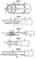
- FIG. 1 there is indicated at 1 a jar of vacuum cans whose cover 2 is applied to the jar with the interposition of a rubber ring 3 having a tongue 4 projecting outward.
- the opening tool according to this exemplary embodiment of the invention comprises a handle 5 carrying a tube 6 made of metal or any other suitable material of good mechanical strength, the free end of which is divided into two half-arms tubes 7 by a longitudinal slot 8 intended to receive the tongue 4 for clamping between the four lips 9 opposite two by two of the two branches 7.
- the width of the slot 8 is less than the thickness of the rubber tongue 4 which is thus tightened when this tongue is introduced between the two half-tubes 7 by pushing the tool in a tangential horizontal direction relative to the jar .
- the free ends of its two branches 7 have a spacing greater than the thickness of the tongue, for example by presenting a flared tray 10 composed of the two ends of the branches or half tubes.
- the outside diameter of the tube 6 must obviously not exceed the radial extent of the tongue 4, the outer end of which protrudes from the edge of the tool opposite the base of this tongue.
- the external surface of the clamping arms can have various arrangements of bosses or grooves against which the base of the tongue rests, favoring the drawing in question.
- each of the two branches of the tool clamping fork can be modified while using the principle of clamping the tongue between opposite lips.
- Figure 5 there is shown a variant of Figure 4 comprising two branches with a profile provided with a central membrane 13 which can strengthen the branches while having additional clamping lips.
- FIG. 5 representing the forked part of the tool with a transverse section of the fork, there is also indicated at 14 one of the longitudinal grooves which can be provided on the outer periphery of the forked part and at 15 a transverse groove.
- Such grooves can on the one hand oppose the sliding of the tongue on the tool during its rotation while strengthening the clamping branches.
- branches with profile in half-tubes which characterize the invention can be obtained by various manufacturing processes, in particular by processes for shaping and assembling the tool making it possible to obtain this tool starting, for example, from flat metal bars intended to be cut and stamped instead of from tubes.
- FIG. 6 shows the use of two clamping arms 16 constituted by two separate parts whose ends 17 opposite the entry 18 of the housing of the tongue 4 are fixed, for example by welding, to an internal wedge 19 does not extending only over a fraction of the length of the branches, the assembly then being intended to be mounted in a handle 5.
- Obtaining clamping branches can also be obtained by folding a profile bar in a half-tube as shown in FIG. 7 in which we see a handle 5 carrying one end of a bar 20 with a profile in a half-tube. the other end of which 21 has been folded back at 22 to form a shorter branch up to the entrance 23 of the gap 24 intended to receive the tongue 4.
- the entrance 23 is thus between the handle 5 and the bottom of the housing of the tongue 4 which is introduced between the two branches 20-21 by tangential traction of the tool instead of being introduced by pushing the tool.
- Figure 7 a variant in which the tool consists of a handle 5 and a tubular piece of sufficient mechanical strength 26 having a curved slot 27 of which l entry 28 is towards the handle and which extends towards the front of the tool, stopping before the end of this tool so as to still allow the engagement of the tongue through the slot 27 by pulling the tool.
- the free end of the tube constituting the two clamping arms can receive a complementary end piece, for example a drilling punch or cutting blade for another use.
Landscapes
- Engineering & Computer Science (AREA)
- Mechanical Engineering (AREA)
- Devices For Opening Bottles Or Cans (AREA)
- Food Preservation Except Freezing, Refrigeration, And Drying (AREA)
- Storage Of Fruits Or Vegetables (AREA)
- Agricultural Chemicals And Associated Chemicals (AREA)
- Control And Other Processes For Unpacking Of Materials (AREA)
- Table Equipment (AREA)
- Packages (AREA)
Priority Applications (1)
| Application Number | Priority Date | Filing Date | Title |
|---|---|---|---|
| AT83400090T ATE23983T1 (de) | 1982-01-14 | 1983-01-13 | Anlage zum oeffnen von unter vaekuum stehenden einmachgefaessen. |
Applications Claiming Priority (2)
| Application Number | Priority Date | Filing Date | Title |
|---|---|---|---|
| FR8200525 | 1982-01-14 | ||
| FR8200525A FR2519623B1 (fr) | 1982-01-14 | 1982-01-14 | Dispositif permettant l'ouverture des bocaux de conserve sous vide |
Publications (3)
| Publication Number | Publication Date |
|---|---|
| EP0084496A2 true EP0084496A2 (de) | 1983-07-27 |
| EP0084496A3 EP0084496A3 (en) | 1983-08-10 |
| EP0084496B1 EP0084496B1 (de) | 1986-12-03 |
Family
ID=9269985
Family Applications (1)
| Application Number | Title | Priority Date | Filing Date |
|---|---|---|---|
| EP83400090A Expired EP0084496B1 (de) | 1982-01-14 | 1983-01-13 | Anlage zum Öffnen von unter Väkuum stehenden Einmachgefässen |
Country Status (4)
| Country | Link |
|---|---|
| EP (1) | EP0084496B1 (de) |
| AT (1) | ATE23983T1 (de) |
| DE (1) | DE3368042D1 (de) |
| FR (1) | FR2519623B1 (de) |
Family Cites Families (2)
| Publication number | Priority date | Publication date | Assignee | Title |
|---|---|---|---|---|
| FR694252A (fr) * | 1930-04-22 | 1930-12-02 | Clef à tube pour ouvrir les boîtes de conserves | |
| FR79338E (fr) * | 1961-03-10 | 1962-11-16 | Ouvre-bocal |
-
1982
- 1982-01-14 FR FR8200525A patent/FR2519623B1/fr not_active Expired
-
1983
- 1983-01-13 DE DE8383400090T patent/DE3368042D1/de not_active Expired
- 1983-01-13 EP EP83400090A patent/EP0084496B1/de not_active Expired
- 1983-01-13 AT AT83400090T patent/ATE23983T1/de active
Also Published As
| Publication number | Publication date |
|---|---|
| EP0084496A3 (en) | 1983-08-10 |
| EP0084496B1 (de) | 1986-12-03 |
| ATE23983T1 (de) | 1986-12-15 |
| FR2519623B1 (fr) | 1986-01-31 |
| DE3368042D1 (en) | 1987-01-15 |
| FR2519623A1 (fr) | 1983-07-18 |
Similar Documents
| Publication | Publication Date | Title |
|---|---|---|
| FR2775679A1 (fr) | Ouvre-boite | |
| FR2753120A1 (fr) | Dispositif de pince coupe-tube pour couper transversalement un tube en matiere plastique | |
| EP2519132B1 (de) | Entfernbarer griff | |
| CH650188A5 (fr) | Outil de blocage a long bec. | |
| CH625864A5 (de) | ||
| FR3037368A3 (fr) | Dispositif de verrouillage avec des positions reglables du volant a main de verrouillage. | |
| EP0084496B1 (de) | Anlage zum Öffnen von unter Väkuum stehenden Einmachgefässen | |
| FR2692832A1 (fr) | Dispositif tendeur pour une chaîne à scier. | |
| CH681519A5 (de) | ||
| EP0686369A1 (de) | Schneebesengriff | |
| EP0550623A1 (de) | Vorrichtung und verfahren zum anbringen eines taues um einen festmacherpfosten | |
| EP3795877A1 (de) | Schlauchklemme | |
| EP1082264B1 (de) | Öffner zum öffnen von gefässen mit schraubverschluss | |
| FR3084604A1 (fr) | Pince de serrage d’un collier de serrage | |
| FR2778839A1 (fr) | Pince a biopsie | |
| EP0835617A1 (de) | Gürtelschnalle | |
| FR2508368A1 (fr) | Dispositif de serrage pour fixer par serrage un corps creux fendu sur un bord comportant un bourrelet | |
| FR2849146A1 (fr) | Collier de serrage debrayable | |
| FR2678503A1 (fr) | Ustensile de cuisson a poignee inamovible. | |
| FR2523028A1 (fr) | Poignee-poussoir de prehension manuelle pour machines a bois | |
| CH363863A (fr) | Dispositif de fixation | |
| FR2705048A1 (fr) | Dispositif de liaison entre le manche et l'organe actif d'un outil de serrage et desserrage. | |
| BE844517A (fr) | Outil en forme de pince pour desserrer le capuchon de fermeture a vis d'un recipient | |
| FR2682310A1 (fr) | Pince de traction autoserrante pour le redressement d'elements de carrosserie deformes. | |
| FR2883340A1 (fr) | Dispositif de fixation d'un anneau d'arrimage sur un element porteur et support le comportant |
Legal Events
| Date | Code | Title | Description |
|---|---|---|---|
| PUAI | Public reference made under article 153(3) epc to a published international application that has entered the european phase |
Free format text: ORIGINAL CODE: 0009012 |
|
| PUAL | Search report despatched |
Free format text: ORIGINAL CODE: 0009013 |
|
| AK | Designated contracting states |
Designated state(s): AT BE CH DE FR IT LI |
|
| AK | Designated contracting states |
Designated state(s): AT BE CH DE FR IT LI |
|
| 17P | Request for examination filed |
Effective date: 19840125 |
|
| GRAA | (expected) grant |
Free format text: ORIGINAL CODE: 0009210 |
|
| AK | Designated contracting states |
Kind code of ref document: B1 Designated state(s): AT BE CH DE FR IT LI |
|
| PG25 | Lapsed in a contracting state [announced via postgrant information from national office to epo] |
Ref country code: IT Free format text: LAPSE BECAUSE OF FAILURE TO SUBMIT A TRANSLATION OF THE DESCRIPTION OR TO PAY THE FEE WITHIN THE PRESCRIBED TIME-LIMIT;WARNING: LAPSES OF ITALIAN PATENTS WITH EFFECTIVE DATE BEFORE 2007 MAY HAVE OCCURRED AT ANY TIME BEFORE 2007. THE CORRECT EFFECTIVE DATE MAY BE DIFFERENT FROM THE ONE RECORDED. Effective date: 19861203 Ref country code: AT Effective date: 19861203 |
|
| REF | Corresponds to: |
Ref document number: 23983 Country of ref document: AT Date of ref document: 19861215 Kind code of ref document: T |
|
| REF | Corresponds to: |
Ref document number: 3368042 Country of ref document: DE Date of ref document: 19870115 |
|
| PLBE | No opposition filed within time limit |
Free format text: ORIGINAL CODE: 0009261 |
|
| STAA | Information on the status of an ep patent application or granted ep patent |
Free format text: STATUS: NO OPPOSITION FILED WITHIN TIME LIMIT |
|
| 26N | No opposition filed | ||
| PG25 | Lapsed in a contracting state [announced via postgrant information from national office to epo] |
Ref country code: LI Effective date: 19880131 Ref country code: CH Effective date: 19880131 |
|
| REG | Reference to a national code |
Ref country code: CH Ref legal event code: PL |
|
| PG25 | Lapsed in a contracting state [announced via postgrant information from national office to epo] |
Ref country code: DE Effective date: 19881001 |
|
| PGFP | Annual fee paid to national office [announced via postgrant information from national office to epo] |
Ref country code: FR Payment date: 19980130 Year of fee payment: 16 |
|
| PGFP | Annual fee paid to national office [announced via postgrant information from national office to epo] |
Ref country code: BE Payment date: 19980227 Year of fee payment: 16 |
|
| PG25 | Lapsed in a contracting state [announced via postgrant information from national office to epo] |
Ref country code: BE Free format text: LAPSE BECAUSE OF NON-PAYMENT OF DUE FEES Effective date: 19990131 |
|
| BERE | Be: lapsed |
Owner name: BISSON JEAN Effective date: 19990131 |
|
| PG25 | Lapsed in a contracting state [announced via postgrant information from national office to epo] |
Ref country code: FR Free format text: LAPSE BECAUSE OF NON-PAYMENT OF DUE FEES Effective date: 19990930 |
|
| REG | Reference to a national code |
Ref country code: FR Ref legal event code: ST |