EP0084507A1 - Système d'allumage pour moteur à combustion interne - Google Patents
Système d'allumage pour moteur à combustion interne Download PDFInfo
- Publication number
- EP0084507A1 EP0084507A1 EP83400140A EP83400140A EP0084507A1 EP 0084507 A1 EP0084507 A1 EP 0084507A1 EP 83400140 A EP83400140 A EP 83400140A EP 83400140 A EP83400140 A EP 83400140A EP 0084507 A1 EP0084507 A1 EP 0084507A1
- Authority
- EP
- European Patent Office
- Prior art keywords
- transistor
- ignition system
- circuit
- operating
- switching device
- Prior art date
- Legal status (The legal status is an assumption and is not a legal conclusion. Google has not performed a legal analysis and makes no representation as to the accuracy of the status listed.)
- Withdrawn
Links
Images

Classifications
-
- F—MECHANICAL ENGINEERING; LIGHTING; HEATING; WEAPONS; BLASTING
- F02—COMBUSTION ENGINES; HOT-GAS OR COMBUSTION-PRODUCT ENGINE PLANTS
- F02P—IGNITION, OTHER THAN COMPRESSION IGNITION, FOR INTERNAL-COMBUSTION ENGINES; TESTING OF IGNITION TIMING IN COMPRESSION-IGNITION ENGINES
- F02P5/00—Advancing or retarding ignition; Control therefor
- F02P5/04—Advancing or retarding ignition; Control therefor automatically, as a function of the working conditions of the engine or vehicle or of the atmospheric conditions
- F02P5/145—Advancing or retarding ignition; Control therefor automatically, as a function of the working conditions of the engine or vehicle or of the atmospheric conditions using electrical means
- F02P5/15—Digital data processing
- F02P5/1502—Digital data processing using one central computing unit
-
- Y—GENERAL TAGGING OF NEW TECHNOLOGICAL DEVELOPMENTS; GENERAL TAGGING OF CROSS-SECTIONAL TECHNOLOGIES SPANNING OVER SEVERAL SECTIONS OF THE IPC; TECHNICAL SUBJECTS COVERED BY FORMER USPC CROSS-REFERENCE ART COLLECTIONS [XRACs] AND DIGESTS
- Y02—TECHNOLOGIES OR APPLICATIONS FOR MITIGATION OR ADAPTATION AGAINST CLIMATE CHANGE
- Y02T—CLIMATE CHANGE MITIGATION TECHNOLOGIES RELATED TO TRANSPORTATION
- Y02T10/00—Road transport of goods or passengers
- Y02T10/10—Internal combustion engine [ICE] based vehicles
- Y02T10/40—Engine management systems
Definitions
- This invention relates to an ignition system for an internal combustion engine and more specifically to a circuit that isolates a computer, analyzing the operation of an engine, from an ignition system that operates the engine.
- An ignition system for an internal combustion engine generates timing pulses, which indicate the instant during a piston stroke that its respective spark plug should be fired, and distributes these pulses to the respective spark plugs to cause them to fire in a preset order.
- One example of an ignition system that advances the timing of an ignition system upon an increase in engine speed may be found in U.S. patent 3,240,198 issued March 15, 1966 and entitled “Electrical Apparatus”.
- An electomagnetic pulse generator used with such a system may be found in U.S. patent 3,252,024, issued May 17, 1966 and entitled “Electrical Apparatus”.
- An improvement to such an ignition system may be found in U.S. patent 3,952,715 issued April 27, 1976 and entitled “Variable and Constant Timing for Breakerless Ignition”.
- This last patent discloses a pulse generating system for controlling spark timing in which timing is advanced with increased engine speed and changed independently of engine speed by a voltage biasing means.
- the triggering circuit .in the system may be controlled manually by varying a resistor or controlled by a computer to provide any desired spark timing.
- a computer is .utilized to analyze the operation of an engine it provides an output signal, such as a variable current, to a circuit that operates a transistor in its active region.
- the ignition system is electrically connected to the computer electrical signals, harmful to the computer, may be fed back into the computer by the ignition system.
- This invention provides a circuit that isolates the electrical signals or noise in an ignition system from a computer which controls the timing of the ignition system.
- the invention is characterized by an electro-optical coupling device such as a photosensitive transistor which is controlled by a light emitting diode (LED) to provide a variable light output in response to a variable output signal from' a computer analyzing the operation of an engine.
- the photosensitive transistor is in parallel with a capacitor that is in series with and biases the gate of an (SCR) silicon controlled rectifier switch that controls the discharge of energy from a main storage capacitor through a spark plug in response to trigger pulses timed to the engine operating cycle.
- SCR silicon controlled rectifier switch
- the resistance of the transistor decreases and increases in response to the varying light output of the LED to change the timing of the system.
- the capacitor biasing the SCR switch, discharges to a lower voltage level permitting trigger pulses to pass through to trigger ON the SCR switch at a lower level.
- the predetermined current at which the advance begins is determined by a diode in series with the base of the transistor. The diode does not conduct until the voltage across a resistor reaches a predetermined voltage which corresponds to a specific current from the computer.
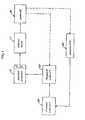
- FIGURE 1 illustrates a block diagram of an ignition system that includes an energy storage section 10; a spark plug 11 for receiving the stored energy and for igniting fuel in an internal combustion engine 40; a trigger circuit 50 for generating trigger pulses and suppling them to the energy storage section 10 to release electrical energy to the spark plug 11 in timed relation to the operating cycle of the engine 40; and a timing circuit 100 for advancing the time that the trigger circuit releases the electrical energy from the storage 10 to the spark plug 11.
- the energy storage section 10 includes a distributor to distribute the energy released to each spark plug in the proper sequence in the operating cycle of the engine 40.
- FIGURE 2 illustrates an ignition system constructed according to the invention for supplying timed spark discharges from spark plug 11 to an internal combustion engine 40. Any number of spark plugs 11 may be used and electrical energy may be distributed to the spark plugs in timed relation to the engine through a distributor (not shown) as described in U.S. patent 3,240,198.
- Direct current power 13 for the system may be supplied by a magneto or generator through a full wave rectifier or any other suitable source such as a battery.
- the voltage may also be regulated by a Zener diode 15 and diode 17 connected in series across leads 19 and 21.
- Lead 19 is connected to source 13 through a diode 23 and lead 21 is connected to source 13 through an inductor 25.
- a main storage capacitor 27 connected between leads 19 and 21 is periodically charged by D C source 13 through diode 23 and inductor 25.
- Capacitor 27 discharges when a silicon controlled rectifier 29 is triggered to conduct by a triggering pulse from trigger circuit. 50.
- the capacitor 27 upon discharging will provide sufficient energy through transformer 33, which has a primary winding 35 connected in series with silicon controlled rectifier 29 across leads 19 and 21 and a secondary winding 37 connected in series with spark plug 11, to provide a suitable spark at spark plug 11.
- An electromagnetic pulse generator similar to that shown in U.S. patent 3,252,024 is shown generally as 30.
- the generator includes a trigger wheel 39 having a plurality of projections or vanes 41 equal to the number of spark plugs 11 and is rotated by the crankshaft of engine 40.
- the vanes 41 of trigger wheel 39 when rotated, pass through the flux of a permanent magnet 43, having a pickup coil 45 wound thereon. Each time a vane 41 passes through the flux of the permanent magnet a pulse is generated in pickup coil 45.
- the amplitude of each pulse increases with an increase in the speed of trigger wheel 39.
- One end of coil 45 is connected through a lead 47 to the cathode of a silicon controlled rectifier 49.
- Capacitor 53 is the means for supplying a voltage bias in the gate of SCR 49.
- the timing circuit 100 of the invention is connected in parallel with capacitor 53 to control the voltage to which capacitor 53 discharges to between trigger pulses and hence control t. bias on the gate of SCR 49.
- the cathode of SCR 49 is also commected to the gate of SCR 29 through a lead 59.
- a diode 77 is connected across leads 47 and 57 to keep the reverse gate to cathode voltage at a low value.
- a capacitor 65 is connected to lead 21 through a diode 67 to the junction of resistor 61 and 63.
- the capacitor 65 is also connected to the anode SCR 49.
- Radio frequency suppression may be provided for SCR 49 by a resistor 73 and a capacitor 75 connected in parallel between leads 47 and 57 across the gate to cathode circuit of the SCR 49.
- RF suppression may be provided for SCR 29 by a resistor 78 and a capacitor 79 connected in parallel between leads 59 and 29 across the gate to cathode circuit of SCR 29.
- the ignition circuit operates as follows: capacitor 65 and 27 are fully charged by DC source 13 between successive pulses generated in pickup coil 45.
- the gate of SCR 49 reaches its threshold voltage in response to a pulse from pickup coil 45, the SCR 49 conducts and capacitor 65 discharges through the SCR 49 to provide a pulse through the gate of SCR 29 so that it conducts and discharges capacitor 27 through the primary winding 35 of transformer 33.
- This induces a high voltage at secondary winding 37 causing a spark discharge across the gap of spark plug 11.
- the timing of the spark discharge in the engine cycle is determined by the amplitude of the trigger pulse from the electromagnetic pulse generating means 30 and the voltage on capacitor 53 at the time the trigger pulse is generated.
- the voltage on capacitor 53 is determined by the amplitude of the trigger pulse and by the value of the resistance of transistor 125 of timing circuit 100.
- a trigger pulse upon gating SCR 49 charges capacitor 53 to a voltage corresponding to the amplitude of the trigger pulse and, in the interval between trigger pulses, the capacitor 53 discharges through timing circuit 100 to a voltage determined by the resistance value of transistor 125.
- a trigger pulse from the generator 30 gates SCR 49 ON when its amplitude exceeds the voltage capacitor 53 has discharged'to in the interval between pulses.
- Timing circuit 100 controls the discharging of capacitor 53 by transistor 125.
- Photosensitive transistor 125 is operated in its active region (as a resistor) over a predetermined range of current regardless of engine speed so that its resistance is not substantially a constant value during a portion of its operation.
- capacitor 53 discharges to a lower level permitting trigger pulses from the generator 30 to pass to SCR 49 at a lower voltage level. This triggers SCR 49 ON earlier in the operating cycle of the engine, hence advancing the timing.
- the timing circuit 100 receives computer output current 60, of 4 to 20 milliamperes, and reduces the current to operate the transistor 125 in its active range and provide a 7 degree timing change for that range.
- Resistor 101 has a resistance value so that the voltage developed from the current will reach the forward voltage drop of the diode 112 at 4 milliamperes.
- Resistor 102, 103, and 104 have resistances designed to provide a current though the LED 125 so that the light sensitive transistor 125 functions as a variable resistor. This provides a linear advance as the computer current 60 increases to 20 milliamperes.
- the value of resistor 102 and diode 111 may also be varied to change the slope of the current to the LED 120 if the gain of transistor 125 is not linear. At a predetermined voltage level across resistor 101, diode 111 will conduct, changing the amount of current to the optical coupler 130 (LED 120 and transistor 125).
- Resistors 102, 103, and 104 may also be varied to change the slope of the current to LED 120 and, therefore, change the advance of the timing pulse with speed to fit a desired curve. If desired the circuit 150 may be grounded.
Landscapes
- Engineering & Computer Science (AREA)
- Theoretical Computer Science (AREA)
- Signal Processing (AREA)
- Chemical & Material Sciences (AREA)
- Combustion & Propulsion (AREA)
- Mechanical Engineering (AREA)
- General Engineering & Computer Science (AREA)
- Ignition Installations For Internal Combustion Engines (AREA)
- Electrical Control Of Ignition Timing (AREA)
Applications Claiming Priority (2)
| Application Number | Priority Date | Filing Date | Title |
|---|---|---|---|
| US341030 | 1982-01-20 | ||
| US06/341,030 US4446841A (en) | 1982-01-20 | 1982-01-20 | Photoelectric isolation circuit for an internal combustion engine ignition system |
Publications (1)
| Publication Number | Publication Date |
|---|---|
| EP0084507A1 true EP0084507A1 (fr) | 1983-07-27 |
Family
ID=23335975
Family Applications (1)
| Application Number | Title | Priority Date | Filing Date |
|---|---|---|---|
| EP83400140A Withdrawn EP0084507A1 (fr) | 1982-01-20 | 1983-01-20 | Système d'allumage pour moteur à combustion interne |
Country Status (3)
| Country | Link |
|---|---|
| US (1) | US4446841A (fr) |
| EP (1) | EP0084507A1 (fr) |
| JP (1) | JPS58155279A (fr) |
Cited By (1)
| Publication number | Priority date | Publication date | Assignee | Title |
|---|---|---|---|---|
| CN103968417A (zh) * | 2014-05-29 | 2014-08-06 | 周成龙 | 光敏自动控制电子点烟器 |
Families Citing this family (15)
| Publication number | Priority date | Publication date | Assignee | Title |
|---|---|---|---|---|
| US4469952A (en) * | 1982-05-28 | 1984-09-04 | Snap-On Tools Corporation | Adapter for diesel-engine-timing meter |
| JPS60195378A (ja) * | 1984-03-16 | 1985-10-03 | Sanshin Ind Co Ltd | 内燃機関の点火時期制御装置 |
| US5040519A (en) * | 1987-02-09 | 1991-08-20 | Outboard Marine Corporation | System to prevent reverse engine operation |
| US5038743A (en) * | 1987-02-09 | 1991-08-13 | Outboard Marine Corporation | Dual schedule ignition system |
| CA1296760C (fr) * | 1987-02-09 | 1992-03-03 | Gregry M. Remmers | Systeme de demarrage electronique |
| US4813393A (en) * | 1987-10-27 | 1989-03-21 | Lee Hong Maw | Electronic ignition system |
| US5268642A (en) * | 1990-10-31 | 1993-12-07 | Central Glass Company Limited | Method and apparatus for measuring electrical conductivity of liquid |
| US5239209A (en) * | 1991-06-17 | 1993-08-24 | Minnesota Mining And Manufacturing Company | Zero crossing detection circuit |
| US5345910A (en) * | 1993-04-19 | 1994-09-13 | Outboard Marine Corporation | Engine ignition system having improved warmup advanced timing control |
| US5789960A (en) * | 1996-09-04 | 1998-08-04 | Control Gaging, Inc. | Universal input circuit including opto-isolator and retriggerable monostable multivibrator |
| DE10208697A1 (de) * | 2002-02-28 | 2003-09-11 | Volkswagen Ag | Zündendstufe |
| DE602007012823D1 (de) * | 2007-03-07 | 2011-04-14 | Martin Charles | Schaltkreis und Verfahren zum Überprüfen der Impedanz von Elektroden und zur Steuerung der Intensität eines elektrischen Stimulus |
| EP2124136B1 (fr) * | 2008-05-23 | 2012-08-22 | Charles Martin | Dispositif mains libres pour télécommande |
| US9491821B2 (en) * | 2014-02-17 | 2016-11-08 | Peter W. Shackle | AC-powered LED light engine |
| CN104791169A (zh) * | 2015-04-20 | 2015-07-22 | 余姚市奥鑫电器有限公司 | 延迟点火控制装置 |
Citations (3)
| Publication number | Priority date | Publication date | Assignee | Title |
|---|---|---|---|---|
| US3472216A (en) * | 1968-03-06 | 1969-10-14 | Willis D Clyborne | Engine ignition system |
| US3952715A (en) * | 1974-05-06 | 1976-04-27 | The Bendix Corporation | Variable and constant timing for breakerless ignition |
| FR2477233A1 (fr) * | 1980-03-03 | 1981-09-04 | Bosch Gmbh Robert | Montage pour l'allumage de moteurs a combustion interne |
Family Cites Families (5)
| Publication number | Priority date | Publication date | Assignee | Title |
|---|---|---|---|---|
| US4087706A (en) * | 1975-11-24 | 1978-05-02 | Hynes Electric Heating Company | Electronic level switch control setup |
| FR2378187A1 (fr) * | 1977-01-21 | 1978-08-18 | Renault | Circuit electronique de prelevement et de mise en forme d'un signal rupteur |
| US4197471A (en) * | 1977-09-29 | 1980-04-08 | Texas Instruments Incorporated | Circuit for interfacing between an external signal and control apparatus |
| JPS566533A (en) * | 1979-06-28 | 1981-01-23 | Jieru Syst:Kk | Solid-state relay |
| US4380224A (en) * | 1981-07-31 | 1983-04-19 | The Bendix Corporation | Ignition system for an internal combustion engine |
-
1982
- 1982-01-20 US US06/341,030 patent/US4446841A/en not_active Expired - Fee Related
-
1983
- 1983-01-20 JP JP58007986A patent/JPS58155279A/ja active Pending
- 1983-01-20 EP EP83400140A patent/EP0084507A1/fr not_active Withdrawn
Patent Citations (3)
| Publication number | Priority date | Publication date | Assignee | Title |
|---|---|---|---|---|
| US3472216A (en) * | 1968-03-06 | 1969-10-14 | Willis D Clyborne | Engine ignition system |
| US3952715A (en) * | 1974-05-06 | 1976-04-27 | The Bendix Corporation | Variable and constant timing for breakerless ignition |
| FR2477233A1 (fr) * | 1980-03-03 | 1981-09-04 | Bosch Gmbh Robert | Montage pour l'allumage de moteurs a combustion interne |
Cited By (1)
| Publication number | Priority date | Publication date | Assignee | Title |
|---|---|---|---|---|
| CN103968417A (zh) * | 2014-05-29 | 2014-08-06 | 周成龙 | 光敏自动控制电子点烟器 |
Also Published As
| Publication number | Publication date |
|---|---|
| US4446841A (en) | 1984-05-08 |
| JPS58155279A (ja) | 1983-09-14 |
Similar Documents
| Publication | Publication Date | Title |
|---|---|---|
| EP0084507A1 (fr) | Système d'allumage pour moteur à combustion interne | |
| US3952715A (en) | Variable and constant timing for breakerless ignition | |
| US3831571A (en) | Variable dwell ignition system | |
| EP0297584B1 (fr) | Système d'allumage pour moteur à combustion interne | |
| US5060623A (en) | Spark duration control for a capacitor discharge ignition system | |
| EP0369236A2 (fr) | Dispositif et méthode d'allumage d'une turbine motrice | |
| US4083347A (en) | High energy spark ignition system, particularly for internal combustion engines | |
| US5032969A (en) | Turbine engine igniter exciter circuit | |
| US4404940A (en) | Engine speed limiting circuit | |
| US3729647A (en) | Spark ignition systems | |
| US3941110A (en) | Ignition system for internal combustion engines | |
| US3275884A (en) | Electrical apparatus for generating current pulses | |
| US4162665A (en) | Multi-spark ignition system for internal combustion engines | |
| US4186711A (en) | Ignition device with speed limitation for internal combustion engines | |
| US4380224A (en) | Ignition system for an internal combustion engine | |
| EP0040009B1 (fr) | Circuit de commande combiné de l'allumage et de l'injection pour moteur à combustion interne | |
| US3383555A (en) | Regulated capacitor discharge ignition system | |
| US4558683A (en) | Ignition system in internal combustion engine | |
| US4445490A (en) | Ignition system for an internal combustion engine | |
| US4491122A (en) | Anti-reverse operation of solid state inductive magneto | |
| US4053823A (en) | Ignition arc monitor circuit | |
| US4562811A (en) | Ignition circuit | |
| GB1458731A (en) | Ignition apparatus for internal combustion engine | |
| US4149509A (en) | Breakerless ignition system | |
| US4346690A (en) | CD Ignition with isolation circuit to provide immediate recharging of the charge capacitor |
Legal Events
| Date | Code | Title | Description |
|---|---|---|---|
| PUAI | Public reference made under article 153(3) epc to a published international application that has entered the european phase |
Free format text: ORIGINAL CODE: 0009012 |
|
| 17P | Request for examination filed |
Effective date: 19830126 |
|
| AK | Designated contracting states |
Designated state(s): DE FR GB IT |
|
| STAA | Information on the status of an ep patent application or granted ep patent |
Free format text: STATUS: THE APPLICATION IS DEEMED TO BE WITHDRAWN |
|
| 18D | Application deemed to be withdrawn |
Effective date: 19840511 |
|
| RIN1 | Information on inventor provided before grant (corrected) |
Inventor name: VAN SICLEN, HOWARD EDGAR, JR. |