EP0084523A2 - Verfahren zum automatischen Beschichten von Werkstücken auf einem Fliessband und Vorrichtung zur Ausführung dieses Verfahrens - Google Patents
Verfahren zum automatischen Beschichten von Werkstücken auf einem Fliessband und Vorrichtung zur Ausführung dieses Verfahrens Download PDFInfo
- Publication number
- EP0084523A2 EP0084523A2 EP83830001A EP83830001A EP0084523A2 EP 0084523 A2 EP0084523 A2 EP 0084523A2 EP 83830001 A EP83830001 A EP 83830001A EP 83830001 A EP83830001 A EP 83830001A EP 0084523 A2 EP0084523 A2 EP 0084523A2
- Authority
- EP
- European Patent Office
- Prior art keywords
- painting
- painting machine
- pieces
- processing line
- line
- Prior art date
- Legal status (The legal status is an assumption and is not a legal conclusion. Google has not performed a legal analysis and makes no representation as to the accuracy of the status listed.)
- Withdrawn
Links
Images


Classifications
-
- B—PERFORMING OPERATIONS; TRANSPORTING
- B25—HAND TOOLS; PORTABLE POWER-DRIVEN TOOLS; MANIPULATORS
- B25J—MANIPULATORS; CHAMBERS PROVIDED WITH MANIPULATION DEVICES
- B25J5/00—Manipulators mounted on wheels or on carriages
- B25J5/02—Manipulators mounted on wheels or on carriages travelling along a guideway
-
- B—PERFORMING OPERATIONS; TRANSPORTING
- B05—SPRAYING OR ATOMISING IN GENERAL; APPLYING FLUENT MATERIALS TO SURFACES, IN GENERAL
- B05B—SPRAYING APPARATUS; ATOMISING APPARATUS; NOZZLES
- B05B13/00—Machines or plants for applying liquids or other fluent materials to surfaces of objects or other work by spraying, not covered by groups B05B1/00 - B05B11/00
- B05B13/02—Means for supporting work; Arrangement or mounting of spray heads; Adaptation or arrangement of means for feeding work
- B05B13/04—Means for supporting work; Arrangement or mounting of spray heads; Adaptation or arrangement of means for feeding work the spray heads being moved during spraying operation
- B05B13/0431—Means for supporting work; Arrangement or mounting of spray heads; Adaptation or arrangement of means for feeding work the spray heads being moved during spraying operation with spray heads moved by robots or articulated arms, e.g. for applying liquid or other fluent material to three-dimensional [3D] surfaces
- B05B13/0433—Means for supporting work; Arrangement or mounting of spray heads; Adaptation or arrangement of means for feeding work the spray heads being moved during spraying operation with spray heads moved by robots or articulated arms, e.g. for applying liquid or other fluent material to three-dimensional [3D] surfaces the work being vehicle components, e.g. vehicle bodies
-
- B—PERFORMING OPERATIONS; TRANSPORTING
- B25—HAND TOOLS; PORTABLE POWER-DRIVEN TOOLS; MANIPULATORS
- B25J—MANIPULATORS; CHAMBERS PROVIDED WITH MANIPULATION DEVICES
- B25J9/00—Program-controlled manipulators
- B25J9/0093—Program-controlled manipulators co-operating with conveyor means
-
- G—PHYSICS
- G05—CONTROLLING; REGULATING
- G05B—CONTROL OR REGULATING SYSTEMS IN GENERAL; FUNCTIONAL ELEMENTS OF SUCH SYSTEMS; MONITORING OR TESTING ARRANGEMENTS FOR SUCH SYSTEMS OR ELEMENTS
- G05B19/00—Program-control systems
- G05B19/02—Program-control systems electric
- G05B19/418—Total factory control, i.e. centrally controlling a plurality of machines, e.g. direct or distributed numerical control [DNC], flexible manufacturing systems [FMS], integrated manufacturing systems [IMS] or computer integrated manufacturing [CIM]
- G05B19/41815—Total factory control, i.e. centrally controlling a plurality of machines, e.g. direct or distributed numerical control [DNC], flexible manufacturing systems [FMS], integrated manufacturing systems [IMS] or computer integrated manufacturing [CIM] characterised by the cooperation between machine tools, manipulators and conveyor or other workpiece supply system, workcell
- G05B19/4182—Total factory control, i.e. centrally controlling a plurality of machines, e.g. direct or distributed numerical control [DNC], flexible manufacturing systems [FMS], integrated manufacturing systems [IMS] or computer integrated manufacturing [CIM] characterised by the cooperation between machine tools, manipulators and conveyor or other workpiece supply system, workcell manipulators and conveyor only
-
- Y—GENERAL TAGGING OF NEW TECHNOLOGICAL DEVELOPMENTS; GENERAL TAGGING OF CROSS-SECTIONAL TECHNOLOGIES SPANNING OVER SEVERAL SECTIONS OF THE IPC; TECHNICAL SUBJECTS COVERED BY FORMER USPC CROSS-REFERENCE ART COLLECTIONS [XRACs] AND DIGESTS
- Y02—TECHNOLOGIES OR APPLICATIONS FOR MITIGATION OR ADAPTATION AGAINST CLIMATE CHANGE
- Y02P—CLIMATE CHANGE MITIGATION TECHNOLOGIES IN THE PRODUCTION OR PROCESSING OF GOODS
- Y02P90/00—Enabling technologies with a potential contribution to greenhouse gas [GHG] emissions mitigation
- Y02P90/02—Total factory control, e.g. smart factories, flexible manufacturing systems [FMS] or integrated manufacturing systems [IMS]
Definitions
- the present invention relates to a process for automatic ally painting pieces fed in along a processing line which utilizes on the line itself at least a painting machine, such as a so-called painting robot, preferably of the kind provided with an articulated arm, carrying a spraying device controlled, by means of corresponding actuators and electrical position transducers, by an electronic equipment suitable to store a number of predetermined processing procedures and to pilot the painting machine according to said procedures so that said spaying device can be operated in space, time and mode according to a desired program and in a repeated manner.
- a painting machine such as a so-called painting robot, preferably of the kind provided with an articulated arm, carrying a spraying device controlled, by means of corresponding actuators and electrical position transducers, by an electronic equipment suitable to store a number of predetermined processing procedures and to pilot the painting machine according to said procedures so that said spaying device can be operated in space, time and mode according to a desired program and in a repeated manner.
- the automatic painting of pieces (for example the bearing body of cars) f e d in along a processing line takes place by arranging a certain number of painting robots in predetermined fixed positions at the sides of said line, each robot being scheduled to carry out the painting of a certain portion of said pieces.
- the processing line conveyer is caused to advance continuously, normally at a constant speed, and the programming of the painting robots is based on this speed, the spraying devices of which being moved so that they can reach the respective areas to be painted.
- a further drawback of the automatic painting methods actually in use consists in that, as the processing line must always be in movement during the normal running in order to attain a continuous production at a high production rate, said robots cannot always carry out complete and regular paintings, even when the conveyer does not suddenly stop or slow down. In fact some areas of the workpiece are often difficult to paint and the continuous advancing of the piece * does not allow the robot to work properly, for example because the passage time of said areas is too short or because the orientation of said areas is not suitable for a correct projection of a paint spray thereon, as each robot must always "wait" for the piece being painted to be at the right distance.
- a still further drawback of the automatic painting methods actually in use consists in that the programming of said painting robots is too much appro x imative, which does not allow to fully exploit the possibilites of movement of same.
- the teaching step i.e. the storing of processing procedure by an electronic device is carried out with the aid of an operator which execute the painting of a piece which is fed in along the processing line.
- the main object of the present invention is to obviate the above drawbacks related to known systems, by accomplishing an automatic painting process fitted for carrying out regular and uniform paintings over the whole area, whether the conveyer which causes the pieces being painted to advance moves regularly or is caused to slow-down, stop and then start again.
- a further important object of the present invention is to allow the automatic painting even on zones which are difficult to reach and which require a manual painting when known methods are used.
- a still further object of the present invention is to conceive an automatic painting process allowing a very accurate programming so that the possibilites offered by painting machines are exploited at the utmost while times necessary for said processes are reduced.
- a processing line which utilizes on the line itself at least a painting machine, such as a so-called painting robot preferably of the kind provided with an articulated arm, carrying a spraying device and controlled, by means of corresponding actuators and position transducers, by an electronic equipment suitable to store a number of predetermined processing procedures and to pilot the painting machine according to said procedures, so that said device can be operated in space, time and mode according to a desired program and a particular routine, said process being characterized in that it provides the reciprocating motion of said painting machine in a direction which is substantially parallel to the axis of said processing line, being possible to vary, when desired, the relative speed of said painting machine with respect to said pieces to be painted.
- a painting machine such as a so-called painting robot preferably of the kind provided with an articulated arm, carrying a spraying device and controlled, by means of corresponding actuators and position transducers, by an electronic equipment suitable to store a number of predetermined processing procedures and to pilot the painting machine according to said procedures, so that said device can be operated in
- the painting machine can move together with the piece being painted at the same speed or at different speeds so that the spraying device can reach even hidden areas, or it can move in the opposite direction with respect to the feeding in direction of pieces in order to reduce the painting time.
- the painting machine can go on moving while the processing line is slowing down or stopping, so that painting can be regular ly carried out even in these cases.
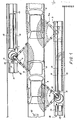
- FIG. 1 a tunnel for the automatic painting of the bearing bodies of cars 2, fed in uninterruptedly by a conveyer along a processing line 3.
- An arrow A in Fig: 1 shows the feeding direction of line 3.
- Painting robots are arranged on both sides of line 3, said robots being of the kind provided with an articulated arm, mounted however, according to the present invention, on respective trucks slidable in a direction parallel to axis 3a of line 3.
- first painting robot placed at one side of line 3 and mounted on a respective truck 5 and at 6 a second painting robot placed on the opposite side and mounted on a respective truck 7.
- second painting robot placed on the opposite side and mounted on a respective truck 7.
- other painting robots can be arranged which are also mounted on respective trucks, disposed in a line one after the other or, if more appropriate, traditional robots can be arranged on one side of the line, these robots cooperating with robots mounted on slidable trucks disposed on the opposite side.
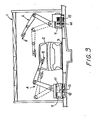
- Each robot carries a spraying device 8 fed in a known manner and movable by means of actuators disposed close to the several articulated joints where position transducers are placed too, which are connected to an electronic equipment suitable to give the different commands and store the predetermined processing procedures.
- Trucks 5 and 7 slide with alternate backward and forward motion along tracks 9 and 10 arranged on beds 18 and 19 parallel to axis 3a of line 3, these tracks extending for a certain length in order to allow a sufficient displacement of the same trucks so that the different painting steps can be carried out.
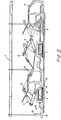
- Each of said trucks 5 and 7 moves along its track by the action of a hydraulic motor 11 or the like, which causes a vertical axis toothed wheel 12 to rotate (Figs: 1, 2, 3 and 4), which meshes with a fixed chain 13, parallel to axis 3a of line 3.
- two idler wheels 20 and 21 are provided on the opposite side of chain 13 with respect to that on which toothed wheel 12 acts.
- the end portions 13a and 13b of chain 13 are fixed to the respective beds 18 and 19 by an anchorage 22 and by spring means 23 respectively which allow the chain to be constantly tightened.
- this spring means comprises a cup-shaped spring preloaded by means of a nut 25, which allows to obtain the complete absence of slack between motor 11 and chain 13, this condition being absolutely necessary in an endless control system.
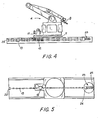
- a magnetic system comprising an E-shaped metal strip 26 and a magnet 27 which run parallel to chain 13 (Fig. 6). Magnet 27 is placed between the upper arms 26a and 26b of the E-shaped strip 26, which therefore form the pole pieces of the magnetic system while the lower arm 26c is slightly wider than the others so that it forms an inclined surface for chain 13. Therefore the latter is always fastened to the magnetic system except when it is close to the toothed wheel 12.
- sliding tracks 9 and 10 are defined by respective groups of three rails which project from beds 18 and 19. More particularly, referring to Figs. 7 and 8, where the only bed 12 has been shown for the sake of simplicity, the corresponding track 9 comprises a central rail 28 having a vertical transverse axis and two side rails 29 and 30, having a horizontal transverse axis. On the central rail 28 are engaged at least two pairs of wheels 31 centrally mounted, with a vertical axis, on the base of truck 5, while on the side rails are respectively engaged a pair of wheels 32 and two pairs of wheels 33 horizontally disposed at the sides of truck 5.
- a device for taking up slacks comprising a tubular eccentric body 34 which is mounted on the shank of screw 35 supporting one of the wheels 32 and is rotatably engaged within a bearing hole 36 formed in truck 5.
- a nut 37 allows wheel 32 to be locked after the adjustment thereof; In this way it is possible to eliminate any slack between the different pairs of wheels and the corresponding rails.
- beds 18 and 19 are provided with a plurality of bulkheads 39 which extend parallel to the corresponding tracks 9 and 10 in order to define a series of channels indicated by reference numerals 40 to 44 in Fig. 7. Said channels are covered by a plurality of suitably shaped guards-41; it is to be noted that channels 41 and 43 are arranged to accommodate flexible ducts 14 and 15 suitable to contain the connecting cables for robots and hoses for oil under pressure, air and paint, while channels 40, 42 and 44 are arranged for blowing in air which then goes out through slits 46, 47, 48 in such a way to prevent dust and dirt from reaching wheels, tracks and chain.
- Robots 4 and 6 can slide to and fro along tracks 9 and 10,the supply connection being always kept. Furthermore, each hydraulic actuator is always controlled by servo- valves and position transducers, for example consisting of resolvers, electrically connected to the electronic equipment.
- An appropriate device such as for example a resolver 50, is provided which reports the speed information of the processing line, in order to allow a complete synchronization of the spraying units with the processing line itself.
- a hydraulic device is also provided which powers the actuators and hydraulic motors intended for the painting units (robots mounted on trucks), suit able flexible connections being arranged.
- the painting units consisting of robots mounted on their respective trucks, either can move to and fro along tracks 9 and 10 or can be kept stationary, in connection with the different processing procedures.
- robot 4 can move from the position shown in solid line (Figs: 1 and 2) to that shown in dotted line at 4a, then again to the starting position and so on.
- robot 6 can move from the position shown in solid line to that shown in dotted line, at 6a, and vice versa.
- the displacement speeds can be varied at will from zero to a speed equal or even higher than the nominal speed of the processing line (that is the speed of the conveyer which feeds in pieces 2 to be painted), in either direction. Speed variations can be suitably scheduled and stored in the electronic equipment.
- robots 4 and 6 can execute the painting cycle without displacing (that is trucks 5 and 7 are station ary).
- trucks 5 and 7 are station ary.
- robots 4 and 6 will execute the processing cycle moving in an opposite direction with respect to the feeding in direction A of pieces, at a speed equal to the difference between the conveyer nominal speed and said slower speed, this being made possible by the presence of trucks.
- Robots can therefore carry out the painting keeping constant parameters while varying the conveyer speed. If the conveyer suddenly stops, as soon as this happens, the painting units will automatically displace in the opposite direction with respect to the feeding in direction A, at a speed equal to the nominal one, so that the relative speed gun-piece is still steady. This displacement will last till the conveyer starts again its moving. Should the latter stop for a longer period than it is necessary to paint the concerned piece, the painting units will go on displacing, as seen above, till the end of the cycle when they return to their waiting position.
- the possibility of moving of the painting inits allows them to perfectly paint even areas which are difficult to reach; in fact, when traditional methods are used, owing to their being stationary, these areas are badly painted or are not painted at all and require a further manual painting;
- the movable units of the present invention it is possible to take the spraying guns to the desired zones, for example even before the same zones to be painted are at a right distance, so that the latter can then be painted by the same units accompanying the movement of the piece being painted, which allows the gun to be suitably displaced towards the innermost points, without creating any interference with the moving piece.
- the equipment of the present invention allows to achieve the greatest capacity exploitation of a painting apparatus.
- the motion of translation of each painting unit is used, causing it to move during the processing cycle, in a direction opposite to the feeding in direction of pieces to be painted, at the same time increasing the delivery of paint in order to reduce the time required for the same processing cycle, at first rising the period of stop.
- the conveyer speed can be increased as much as to attain a nearly null idle time and consequently a higher production per hour, the apparatus capacity being at the utmost.
- the apparatus according to the present invention allows an easy change of painting colours, acting on the same processing line, without being necessary.to reset the whole program, which is on the contrary necessary with the methods actually in use.
- paint hiding power generally varies from one colour to another so that, in order to obtain the same hiding power when colour has to be changed, it is necessary to carry out suitable adjustments, these adjustments even requiring a different programming for each colour. That means that with known methods different processing cycles have to be scheduled and the new programs must be stored, one by one, by the electronic equipment, the number of cycles being substantially equal to that of the designed colours. Therefore storages having a great capacitance are required and consequently very complicated and expensive electronic equipments, while the programming operations are very difficult.
- the teaching is carried out utilizing the same operating painting unit, such as robots 4 and 6 mounted on their respective trucks 5 and 7.
- lines are traced on a pattern piece these lines representing the trajectory of the paint spray, and being then divided in portions having a suitable length, in order to obtain a series of points towards which the spraying gun has to be directed (or a paintbrush, a pencil or the like associated to the gun).
- the painting unit is operated, causing it to move along its respective tracks, and moving the gun till it is directed, as it goes along, towards the marked points, these points being stored.
- An advantage of this procedure is that the teaching can be carried out without interfering with the working shifts and therefore with normal production.
- a further advantage is that it is possible to obtain a better painting because the painting of a stationary piece (or the simulation of its painting) allows to concentrate the attention on the concerned portion, without being afraid that the piece being painted may go out of the processing area of . the painting unit. In this case too it is always possible to carry out the teaching using a teaching unit having a light structure which can be operated by a skilled operator.
- the process according to the present invention provides the longitudinal displacement of the painting units, it is possible to achieve a remarkable progress in carrying out the painting of moving pieces, as the processing times are reduced while the work appears more accurate, being possible to execute a complete painting of the whole piece, also reaching the most hidden areas, no further retouch being required.
- the arrangement for carrying out the process of the invention is suitable to bear parallelism errors between the two side rails as well as between the central rail and the side rails.
- side rails can converge or diverge with respect to each other or to the central rail because only the latter is the guide for a truck.
- side rails can rise or lower with respect to each other without giving rise to interferences as each truck is provided with three pairs of side wheels, two of which on one side (33) and one on the opposite side (32).
- the equipment can provide longitudinal displacement means for each painting unit having whatever structure, different from that described above, using for example a jack, an electromagnetic device or the like as displacement members.
- the longitudinal sliding tracks can be disposed not only on the ground but also at a certain height from earth.
Landscapes
- Engineering & Computer Science (AREA)
- Robotics (AREA)
- Mechanical Engineering (AREA)
- General Engineering & Computer Science (AREA)
- Manufacturing & Machinery (AREA)
- Quality & Reliability (AREA)
- Physics & Mathematics (AREA)
- General Physics & Mathematics (AREA)
- Automation & Control Theory (AREA)
- Spray Control Apparatus (AREA)
Applications Claiming Priority (2)
| Application Number | Priority Date | Filing Date | Title |
|---|---|---|---|
| IT19127/82A IT1153412B (it) | 1982-01-15 | 1982-01-15 | Procedimento per la verniciatura automatica di oggetti avanzanti lungo una linea di lavorazione e apparecchiatura per l'attuazione del medesimo procedimento |
| IT1912782 | 1982-01-15 |
Publications (2)
| Publication Number | Publication Date |
|---|---|
| EP0084523A2 true EP0084523A2 (de) | 1983-07-27 |
| EP0084523A3 EP0084523A3 (de) | 1984-10-17 |
Family
ID=11155015
Family Applications (1)
| Application Number | Title | Priority Date | Filing Date |
|---|---|---|---|
| EP83830001A Withdrawn EP0084523A3 (de) | 1982-01-15 | 1983-01-04 | Verfahren zum automatischen Beschichten von Werkstücken auf einem Fliessband und Vorrichtung zur Ausführung dieses Verfahrens |
Country Status (2)
| Country | Link |
|---|---|
| EP (1) | EP0084523A3 (de) |
| IT (1) | IT1153412B (de) |
Cited By (29)
| Publication number | Priority date | Publication date | Assignee | Title |
|---|---|---|---|---|
| WO1987004968A1 (en) * | 1986-02-25 | 1987-08-27 | Trallfa Robot A/S | Method and robot installation for programmed control of a working tool |
| GB2190312A (en) * | 1986-04-01 | 1987-11-18 | Honda Motor Co Ltd | Painting vehicle bodies |
| US4810538A (en) * | 1987-04-02 | 1989-03-07 | Behr-Industrieanlagen Gmbh & Co. | Method for automatic coating of workpieces |
| WO1989006181A1 (en) * | 1988-01-05 | 1989-07-13 | Abb Trallfa Robot A/S | Method and robot system for repair painting of motorcars |
| AU593788B2 (en) * | 1986-02-25 | 1990-02-22 | Trallfa Robot A/S | Programmed control of a working tool |
| US4931322A (en) * | 1986-04-01 | 1990-06-05 | Honda Giken Kogyo Kabushiki | Method and apparatus for painting object |
| US4977000A (en) * | 1988-09-22 | 1990-12-11 | Honda Giken Kogyo Kabushiki Kaisha | Painting method |
| US5014644A (en) * | 1989-05-23 | 1991-05-14 | Honda Giken Kogyo Kabushiki Kaisha | Apparatus for coating automotive body |
| EP0421791A3 (en) * | 1989-10-05 | 1991-09-18 | Taikisha, Ltd. | Spray painting system |
| DE4017261A1 (de) * | 1990-05-29 | 1991-12-05 | Wagner Int | Verschiebewagen fuer lackier- oder pulverbeschichtungsanlagen |
| EP0464235A1 (de) * | 1989-02-09 | 1992-01-08 | Dsd, Ltd. | Objekt-Handlungs-Steuerungssystem |
| US5090361A (en) * | 1988-05-26 | 1992-02-25 | Honda Giken Kogyo Kabushiki Kaisha | Coating apparatus |
| EP0489979A1 (de) * | 1988-05-17 | 1992-06-17 | Stanley J. Walendowski | Verfahren und Vorrichtung zur Reinigung mit einem Wasserstrahl |
| GB2263422A (en) * | 1992-01-27 | 1993-07-28 | Toyota Motor Co Ltd | Paint apparatus having two robots |
| US5240745A (en) * | 1986-04-01 | 1993-08-31 | Honda Giken Kogyo Kabushiki Kaisha | Method for uniformly painting an object with moving spray guns spaced a constant distance from the surface of the object |
| WO1993018860A1 (de) * | 1992-03-21 | 1993-09-30 | Licentia Patent-Verwaltungs-Gmbh | Verfahren und vorrichtung zum automatischen beschichten von gegenständen mit einer spritzvorrichtung |
| WO1996035555A1 (en) * | 1995-05-08 | 1996-11-14 | Aeg Automation Systems Corporation | Modular robot auxiliary axis system |
| US5645895A (en) * | 1988-09-05 | 1997-07-08 | Honda Giken Kogyo Kabushiki Kaisha | Method for painting a vehicle body |
| EP0875297A3 (de) * | 1997-04-28 | 2002-06-26 | Dürr Systems GmbH | Bearbeitungsanlage zur serienweisen Bearbeitung von Werkstücken |
| WO2004037430A1 (en) * | 2002-10-23 | 2004-05-06 | Fanuc Robotics America, Inc. | Modular painting apparatus |
| WO2008071329A1 (de) | 2006-12-11 | 2008-06-19 | Dürr Systems GmbH | Beschichtungsanlage und verfahren zur serienbeschichtung von werkstücken |
| DE102008007438A1 (de) * | 2008-02-01 | 2009-08-13 | Abb Ag | Verfahren zum Wiederanfahren eines Roboters |
| US8807073B2 (en) | 2009-03-06 | 2014-08-19 | Durr Systems Gmbh | Robot arrangement, in particular in a painting booth |
| DE102013006244A1 (de) * | 2013-04-11 | 2014-10-16 | Volkswagen Aktiengesellschaft | Anordnung eines Industrieroboters zur Handhabung, Montage oder Bearbeitung von Werkstücken |
| JP2019155538A (ja) * | 2018-03-14 | 2019-09-19 | ファナック株式会社 | 協働ロボットの制御装置及び制御方法 |
| CN113997265A (zh) * | 2021-10-29 | 2022-02-01 | 中国矿业大学 | 一种基于机器视觉的重介浅槽疏通装置及操控方法 |
| CN115069473A (zh) * | 2022-05-12 | 2022-09-20 | 中车青岛四方机车车辆股份有限公司 | 一种车体自动喷涂的方法及喷涂系统 |
| CN115178413A (zh) * | 2022-07-07 | 2022-10-14 | 南京鑫之鸿环保科技有限公司 | 循环轨道式自动涂装流水线 |
| CN115755796A (zh) * | 2022-11-08 | 2023-03-07 | 东风柳州汽车有限公司 | 涂装面漆节拍提升方法、装置、设备及存储介质 |
Families Citing this family (1)
| Publication number | Priority date | Publication date | Assignee | Title |
|---|---|---|---|---|
| CN113492073A (zh) * | 2021-05-26 | 2021-10-12 | 江铃汽车股份有限公司 | 汽车涂装工艺用滑撬体的控制方法 |
Family Cites Families (4)
| Publication number | Priority date | Publication date | Assignee | Title |
|---|---|---|---|---|
| JPS5336231B1 (de) * | 1971-07-29 | 1978-10-02 | ||
| JPS6057379B2 (ja) * | 1977-06-02 | 1985-12-14 | 三菱重工業株式会社 | ア−ム動作記憶方法 |
| GB2045463B (en) * | 1979-04-03 | 1983-04-20 | Hall Automation Ltd | Arrangement for controlling an operation performed on a workpiece |
| GB2075217B (en) * | 1980-04-17 | 1983-07-13 | Hall Automation Ltd | Relative position tracking systems |
-
1982
- 1982-01-15 IT IT19127/82A patent/IT1153412B/it active
-
1983
- 1983-01-04 EP EP83830001A patent/EP0084523A3/de not_active Withdrawn
Cited By (40)
| Publication number | Priority date | Publication date | Assignee | Title |
|---|---|---|---|---|
| AU593788B2 (en) * | 1986-02-25 | 1990-02-22 | Trallfa Robot A/S | Programmed control of a working tool |
| WO1987004968A1 (en) * | 1986-02-25 | 1987-08-27 | Trallfa Robot A/S | Method and robot installation for programmed control of a working tool |
| GB2190312A (en) * | 1986-04-01 | 1987-11-18 | Honda Motor Co Ltd | Painting vehicle bodies |
| US4931322A (en) * | 1986-04-01 | 1990-06-05 | Honda Giken Kogyo Kabushiki | Method and apparatus for painting object |
| US5240745A (en) * | 1986-04-01 | 1993-08-31 | Honda Giken Kogyo Kabushiki Kaisha | Method for uniformly painting an object with moving spray guns spaced a constant distance from the surface of the object |
| GB2190312B (en) * | 1986-04-01 | 1990-12-19 | Honda Motor Co Ltd | Method and apparatus for painting object |
| US4810538A (en) * | 1987-04-02 | 1989-03-07 | Behr-Industrieanlagen Gmbh & Co. | Method for automatic coating of workpieces |
| WO1989006181A1 (en) * | 1988-01-05 | 1989-07-13 | Abb Trallfa Robot A/S | Method and robot system for repair painting of motorcars |
| EP0489979A1 (de) * | 1988-05-17 | 1992-06-17 | Stanley J. Walendowski | Verfahren und Vorrichtung zur Reinigung mit einem Wasserstrahl |
| US5090361A (en) * | 1988-05-26 | 1992-02-25 | Honda Giken Kogyo Kabushiki Kaisha | Coating apparatus |
| US5645895A (en) * | 1988-09-05 | 1997-07-08 | Honda Giken Kogyo Kabushiki Kaisha | Method for painting a vehicle body |
| US4977000A (en) * | 1988-09-22 | 1990-12-11 | Honda Giken Kogyo Kabushiki Kaisha | Painting method |
| EP0464235A1 (de) * | 1989-02-09 | 1992-01-08 | Dsd, Ltd. | Objekt-Handlungs-Steuerungssystem |
| US5014644A (en) * | 1989-05-23 | 1991-05-14 | Honda Giken Kogyo Kabushiki Kaisha | Apparatus for coating automotive body |
| EP0421791A3 (en) * | 1989-10-05 | 1991-09-18 | Taikisha, Ltd. | Spray painting system |
| DE4017261A1 (de) * | 1990-05-29 | 1991-12-05 | Wagner Int | Verschiebewagen fuer lackier- oder pulverbeschichtungsanlagen |
| US5336321A (en) * | 1992-01-27 | 1994-08-09 | Toyota Jidosha Kabushiki Kaisha | Paint apparatus having two robots |
| GB2263422B (en) * | 1992-01-27 | 1995-06-07 | Toyota Motor Co Ltd | Paint apparatus having two robots |
| GB2263422A (en) * | 1992-01-27 | 1993-07-28 | Toyota Motor Co Ltd | Paint apparatus having two robots |
| WO1993018860A1 (de) * | 1992-03-21 | 1993-09-30 | Licentia Patent-Verwaltungs-Gmbh | Verfahren und vorrichtung zum automatischen beschichten von gegenständen mit einer spritzvorrichtung |
| US5814375A (en) * | 1992-03-21 | 1998-09-29 | Cegelec Aeg Anlagen Und Automatisierungstechnik Gmbh | Process and device for automatically coating objects with a sprayer |
| WO1996035555A1 (en) * | 1995-05-08 | 1996-11-14 | Aeg Automation Systems Corporation | Modular robot auxiliary axis system |
| US5878952A (en) * | 1995-05-08 | 1999-03-09 | Powell; Thomas M. | Modular robot auxiliary axis system |
| EP0875297A3 (de) * | 1997-04-28 | 2002-06-26 | Dürr Systems GmbH | Bearbeitungsanlage zur serienweisen Bearbeitung von Werkstücken |
| US7650852B2 (en) | 2002-10-23 | 2010-01-26 | Fanuc Robotics America, Inc. | Modular painting apparatus |
| CN100411749C (zh) * | 2002-10-23 | 2008-08-20 | 美国发那科机器人有限公司 | 模块化喷涂装置 |
| WO2004037430A1 (en) * | 2002-10-23 | 2004-05-06 | Fanuc Robotics America, Inc. | Modular painting apparatus |
| WO2008071329A1 (de) | 2006-12-11 | 2008-06-19 | Dürr Systems GmbH | Beschichtungsanlage und verfahren zur serienbeschichtung von werkstücken |
| US9354626B2 (en) | 2008-02-01 | 2016-05-31 | Abb Ag | Method for restarting a robot |
| DE102008007438A1 (de) * | 2008-02-01 | 2009-08-13 | Abb Ag | Verfahren zum Wiederanfahren eines Roboters |
| DE102008007438B4 (de) * | 2008-02-01 | 2012-11-29 | Abb Ag | Verfahren zum Wiederanfahren eines Roboters |
| US8807073B2 (en) | 2009-03-06 | 2014-08-19 | Durr Systems Gmbh | Robot arrangement, in particular in a painting booth |
| DE102013006244A1 (de) * | 2013-04-11 | 2014-10-16 | Volkswagen Aktiengesellschaft | Anordnung eines Industrieroboters zur Handhabung, Montage oder Bearbeitung von Werkstücken |
| JP2019155538A (ja) * | 2018-03-14 | 2019-09-19 | ファナック株式会社 | 協働ロボットの制御装置及び制御方法 |
| US10882188B2 (en) | 2018-03-14 | 2021-01-05 | Fanuc Corporation | Controller and control method for collaborative robot |
| CN113997265A (zh) * | 2021-10-29 | 2022-02-01 | 中国矿业大学 | 一种基于机器视觉的重介浅槽疏通装置及操控方法 |
| CN115069473A (zh) * | 2022-05-12 | 2022-09-20 | 中车青岛四方机车车辆股份有限公司 | 一种车体自动喷涂的方法及喷涂系统 |
| CN115178413A (zh) * | 2022-07-07 | 2022-10-14 | 南京鑫之鸿环保科技有限公司 | 循环轨道式自动涂装流水线 |
| CN115178413B (zh) * | 2022-07-07 | 2023-05-26 | 南京鑫之鸿环保科技有限公司 | 循环轨道式自动涂装流水线 |
| CN115755796A (zh) * | 2022-11-08 | 2023-03-07 | 东风柳州汽车有限公司 | 涂装面漆节拍提升方法、装置、设备及存储介质 |
Also Published As
| Publication number | Publication date |
|---|---|
| IT8219127A0 (it) | 1982-01-15 |
| EP0084523A3 (de) | 1984-10-17 |
| IT1153412B (it) | 1987-01-14 |
Similar Documents
| Publication | Publication Date | Title |
|---|---|---|
| EP0084523A2 (de) | Verfahren zum automatischen Beschichten von Werkstücken auf einem Fliessband und Vorrichtung zur Ausführung dieses Verfahrens | |
| US3606162A (en) | Programmed means for imparting compound motion to a spray gun | |
| US3744032A (en) | Stationary base programmed manipulator arrangement for continuously moving workpiece | |
| US3543947A (en) | Constant-aim work head | |
| US4061062A (en) | Method and a device for the automatic replacement of a workpiece to be machined on a machine-tool | |
| GB2246965A (en) | Coating method and apparatus | |
| US4718810A (en) | High speed transporter for multiple station production line | |
| US4846625A (en) | Device for transferring objects, particularly glass panes | |
| ATE192406T1 (de) | Vorrichtung zum einstellen der zwischenräume bei transportgütern oder gruppen von gütern | |
| US2752883A (en) | Apparatus for conveying articles | |
| US3827309A (en) | Manipulating mechanism | |
| ITBO20000135U1 (it) | Macchina universale per la verniciatura automatica di pannelli od altri manufatti di forma semplice o complessa, sia in movimento che fermi | |
| US4934511A (en) | Automatic conveying system | |
| DE69919966T2 (de) | System zur Förderung unter Verwendung eines Linearmotors | |
| CA1134450A (en) | Submerged arc welding process and apparatus for production of cylindrical bodies | |
| ATE166629T1 (de) | Vorrichtung und verfahren zum automatischen positionieren von ventilen | |
| CN218927792U (zh) | 一种机器人行走轴 | |
| JPS6484309A (en) | Method for controlling operation of joint type robot | |
| GB1390441A (en) | Coating of articles | |
| US3379377A (en) | Spraying apparatus | |
| CN210434757U (zh) | 一种灵活的工件涂装线 | |
| JP2519584B2 (ja) | レシプロ塗装機 | |
| CN113042280A (zh) | 一种工型件自动喷涂设备 | |
| EP0132312A3 (de) | Verfahren und Vorrichtung zur Anwendung in Fertigungsstrassen | |
| JP3054290B2 (ja) | レシプロ塗装装置 |
Legal Events
| Date | Code | Title | Description |
|---|---|---|---|
| PUAI | Public reference made under article 153(3) epc to a published international application that has entered the european phase |
Free format text: ORIGINAL CODE: 0009012 |
|
| AK | Designated contracting states |
Designated state(s): BE DE FR GB SE |
|
| PUAL | Search report despatched |
Free format text: ORIGINAL CODE: 0009013 |
|
| AK | Designated contracting states |
Designated state(s): BE DE FR GB SE |
|
| STAA | Information on the status of an ep patent application or granted ep patent |
Free format text: STATUS: THE APPLICATION IS DEEMED TO BE WITHDRAWN |
|
| 18D | Application deemed to be withdrawn |
Effective date: 19850618 |
|
| RIN1 | Information on inventor provided before grant (corrected) |
Inventor name: DAVINI, GIORGIO |