EP0084580A1 - Chaîne antidérapante pour pneumatiques - Google Patents
Chaîne antidérapante pour pneumatiques Download PDFInfo
- Publication number
- EP0084580A1 EP0084580A1 EP82100479A EP82100479A EP0084580A1 EP 0084580 A1 EP0084580 A1 EP 0084580A1 EP 82100479 A EP82100479 A EP 82100479A EP 82100479 A EP82100479 A EP 82100479A EP 0084580 A1 EP0084580 A1 EP 0084580A1
- Authority
- EP
- European Patent Office
- Prior art keywords
- chain
- tire
- chain according
- bumper
- radial
- Prior art date
- Legal status (The legal status is an assumption and is not a legal conclusion. Google has not performed a legal analysis and makes no representation as to the accuracy of the status listed.)
- Granted
Links
- 230000007704 transition Effects 0.000 claims abstract description 16
- 230000035939 shock Effects 0.000 claims description 30
- 239000006096 absorbing agent Substances 0.000 claims description 27
- 229910000831 Steel Inorganic materials 0.000 claims description 9
- 239000010959 steel Substances 0.000 claims description 9
- 238000006073 displacement reaction Methods 0.000 claims description 3
- 238000013459 approach Methods 0.000 claims description 2
- 230000000284 resting effect Effects 0.000 claims description 2
- 235000014121 butter Nutrition 0.000 claims 1
- 238000013016 damping Methods 0.000 abstract 1
- 238000013461 design Methods 0.000 description 5
- 238000011161 development Methods 0.000 description 4
- 230000036316 preload Effects 0.000 description 3
- XEEYBQQBJWHFJM-UHFFFAOYSA-N Iron Chemical compound [Fe] XEEYBQQBJWHFJM-UHFFFAOYSA-N 0.000 description 2
- 235000010627 Phaseolus vulgaris Nutrition 0.000 description 1
- 244000046052 Phaseolus vulgaris Species 0.000 description 1
- 238000012952 Resampling Methods 0.000 description 1
- 230000006978 adaptation Effects 0.000 description 1
- 238000010516 chain-walking reaction Methods 0.000 description 1
- 239000002131 composite material Substances 0.000 description 1
- 238000010276 construction Methods 0.000 description 1
- 229910052742 iron Inorganic materials 0.000 description 1
- 230000001788 irregular Effects 0.000 description 1
- 239000000463 material Substances 0.000 description 1
- 238000000034 method Methods 0.000 description 1
- 238000012986 modification Methods 0.000 description 1
- 230000004048 modification Effects 0.000 description 1
- 108090000623 proteins and genes Proteins 0.000 description 1
- 230000002787 reinforcement Effects 0.000 description 1
- 238000011179 visual inspection Methods 0.000 description 1
Images




Classifications
-
- B—PERFORMING OPERATIONS; TRANSPORTING
- B60—VEHICLES IN GENERAL
- B60C—VEHICLE TYRES; TYRE INFLATION; TYRE CHANGING; CONNECTING VALVES TO INFLATABLE ELASTIC BODIES IN GENERAL; DEVICES OR ARRANGEMENTS RELATED TO TYRES
- B60C27/00—Non-skid devices temporarily attachable to resilient tyres or resiliently-tyred wheels
- B60C27/06—Non-skid devices temporarily attachable to resilient tyres or resiliently-tyred wheels extending over the complete circumference of the tread, e.g. made of chains or cables
-
- B—PERFORMING OPERATIONS; TRANSPORTING
- B60—VEHICLES IN GENERAL
- B60C—VEHICLE TYRES; TYRE INFLATION; TYRE CHANGING; CONNECTING VALVES TO INFLATABLE ELASTIC BODIES IN GENERAL; DEVICES OR ARRANGEMENTS RELATED TO TYRES
- B60C27/00—Non-skid devices temporarily attachable to resilient tyres or resiliently-tyred wheels
- B60C27/06—Non-skid devices temporarily attachable to resilient tyres or resiliently-tyred wheels extending over the complete circumference of the tread, e.g. made of chains or cables
- B60C27/08—Non-skid devices temporarily attachable to resilient tyres or resiliently-tyred wheels extending over the complete circumference of the tread, e.g. made of chains or cables involving lugs or rings taking up wear, e.g. chain links, chain connectors
-
- B—PERFORMING OPERATIONS; TRANSPORTING
- B60—VEHICLES IN GENERAL
- B60C—VEHICLE TYRES; TYRE INFLATION; TYRE CHANGING; CONNECTING VALVES TO INFLATABLE ELASTIC BODIES IN GENERAL; DEVICES OR ARRANGEMENTS RELATED TO TYRES
- B60C27/00—Non-skid devices temporarily attachable to resilient tyres or resiliently-tyred wheels
- B60C27/06—Non-skid devices temporarily attachable to resilient tyres or resiliently-tyred wheels extending over the complete circumference of the tread, e.g. made of chains or cables
- B60C27/10—Non-skid devices temporarily attachable to resilient tyres or resiliently-tyred wheels extending over the complete circumference of the tread, e.g. made of chains or cables having tensioning means
- B60C27/12—Non-skid devices temporarily attachable to resilient tyres or resiliently-tyred wheels extending over the complete circumference of the tread, e.g. made of chains or cables having tensioning means resilient pretension
Definitions
- the invention relates to a tire and anti-skid chain for rubber-tired vehicles, in particular heavy, fast-moving earthmoving machines, with a running net resting on the tire surface, on the side edges of which adjoining side parts and a tensioning device with spring tensioning elements.
- Previously customary chains had a tensioning chain as a tensioning device, which was guided through retaining rings or eyelets located in the outer edge region of the chain, so that the tensioned chain, when tensioned, formed a polygon more or less approximating the circular shape. Due to the low elasticity of the tire, the period in which the chain was still fairly tight after the onset of wear was relatively short. In order to ensure that the chain rests tightly on the tire for as long as possible, spring tensioning elements were then used, which provided a certain amount of pretension, i.e. the chain was pulled onto the tire surface by the spring tensioning elements despite a certain amount of wear, as long as the preload was present.
- Such a tire and anti-skid chain with spring tensioning elements is known, for example, from “Glückauf", 114 (1978) No. 13, pages 548 and 549, in particular Figure 14 on page 548.
- the spring tensioning elements consist of so-called swirlers located on the inner side wall of the tire. These swirl catchers consist of relatively short telescopic elements that enclose a disc spring.
- the inrapgehakten Drallfän g it are aligned tangentially and form a closed circuit.
- the tensioning of this known chain is carried out in a known manner on the outside of the tire by means of the above-mentioned S annkette p.
- the tensioning chain is tensioned by means of a suitable tool, the tensioning force to be applied having to be applied essentially tangentially with respect to the approximate circular shape of the tensioning chain.
- the prestressing forces to be applied in the known twist catchers in the known chain must be extremely high, because even relatively small radial forces are sufficient to stretch the individual twist catchers, which then leads to the chain lifting off.
- the extreme forces that must prevail in the individual swirl catchers naturally lead to rapid wear of the affected parts.
- the known chains have the disadvantage that the chains can only insufficiently follow the flexing movements of the tire.
- the known chain in order to pull the chain inwards with a certain radial force, enormous high tangential forces are applied in the swirlers. Due to the design, only springs with an extremely steep characteristic curve can be used.
- disc springs are used, which are characterized by high spring force with short travel. This is the reason that a yielding of the swivels due to p caused by the flexing movements of the tire chain irregular Beans ruchun- gene is only very limited extent. As a result, very high forces occur in the chain, which contribute to a relatively rapid wear of the chain.
- the invention has for its object to provide a tire and anti-skid chain of the type mentioned, which can be tensioned more easily than the known chains explained above and which nevertheless ensures that the chain can follow the flexing movements of the tire well.
- the chain according to the invention operates with a radial pretension.
- the chain is then tensioned in the radial direction, which, in contrast to the application of tangential forces in the known tension chain, means that only relatively small forces have to be applied in order to ensure a firm fit of the chain on the tire surface.
- the tensioning of the chain can take place separately at several points, only a fraction of the force with which the tensioning chain was previously tensioned having to be applied, the force applied there being distributed over several points.
- Coil springs are used particularly advantageously as radial clamping elements according to the invention. These coil springs are then arranged approximately radially with respect to the tire in the assembled state. These helical springs then expediently have a flat force-displacement characteristic curve, that is to say that only a relatively small force has to be applied for a specific spring travel.
- the chain can be clamped onto the tire surface with the required force, so that the chain only lifts off the tire surface to a limited extent even when driving fast, on the other hand the chain can follow all the flexing movements of the tire that occur in practice.
- the design of the shock absorber strands, which form the side parts of the chain is defined in more detail.
- the radial tensioning elements according to the invention are connected to these bumper strands.
- the side parts of the chain according to the invention can thus be produced by easily hooking the brackets and the bumper.
- a steel cable is provided on the inner tire side wall, which is closed, for example by means of a cable lock to form a ring.
- a cable lock to form a ring.
- a radial tensioning element for example a helical spring
- the radial tensioning element then being fastened to a retaining ring on the axle side (claims 8 and 9).
- two or more shock absorber strands are combined, as it were, in order to use only one radial tensioning element or one helical spring for several shock deflector strands.
- Tire and anti-skid chains have previously been retensioned when, for example, the driver deemed it necessary after inspecting the chain. In addition to the visual inspection, the driver only had the option of determining whether and if so how far the chain had loosened by moving individual chain links back and forth. When the chain needed to be retensioned, the driver judged on the basis of relatively imprecise criteria. The resampling itself was then carried out in the manner described above by tightening the tension chain, if necessary after some links had previously been removed from the chain. According to the invention, the retensioning of the chain is considerably simplified by the setting elements defined in claim 11.
- the re-tensioning of the chain can be done in a simple manner by rotating the sleeve which is supported on the retaining ring, with the result that the radial tensioning element in question and the bumper strand attached to it are pulled radially inwards. If the wear on the chain has progressed to such an extent that individual links have to be removed from the chain, the sleeve mentioned can be rotated accordingly yielding the radial tensioning elements to the outside for the purpose of adaptation to the now reduced chain.
- the adjustment elements can be rotated extremely quickly, in particular in the development specified in patent claim 13, by means of a pneumatic or electric screwdriver usually used in wheel mounting, which is set to a specific torque. Compared to the time previously required for retensioning the chain, only a fraction of this time is required for retensioning in the chain according to the invention.
- the arrangement specified in claim 14 can always reliably determine when retensioning the chain is required is. From the distance between the display device and, for example, a marking on the radial tensioning element, one can see exactly how far the wear of the chain has progressed, in order then to retension the chain when the mentioned distance has a certain value.
- FIG. 1 shows a vertical cross-sectional view of a wheel as used in heavy, high-speed earthmoving machines.
- the tread net 3 of a tire and anti-skid chain is located on the tread 2 of the tire 1.
- the special design of the running network 3 is not the subject of the present application.
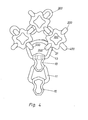
- the running network can be of any design, however, as an example, it should be assumed that the running network 3 is designed as described in a parallel application filed by the same applicant on the same day as this application. Thereafter, the running net 3 consists of essentially square basic bodies which are joined together by means of connecting brackets to form a chain. Part of such a chain running network is in Figure 4 shown in the upper half of the drawing.
- the running net 3 of the tire and anti-skid chain (hereinafter: chain) does not extend to the angled edges of the tire 1, but the edges of the running net are at a certain distance from the tire edges.
- the edges of the tread net 3 are joined both on the side of the tire facing the vehicle, the side I designated here as the inside, and on the outside A, radially extending bumper strips 4 and 5, respectively.
- the side parts of the chain formed by the bumper strips protect the side walls of the tire.
- the ends of the shock absorber strands are held by a steel cable 6, which passes through the shock absorbers provided on the strand ends.
- Radial tensioning elements 7 having coil springs are provided on the outside A.
- the outer ends of the coil springs 7 are hooked into the ends of the shock absorber strands 5, the inner ends of the coil springs 7 are hooked into eyelets of adjusting elements 8 which are fixed to a retaining ring 9 of a U-shaped cross section.
- the helical springs 7 enable the bumper strings 5 to be moved in the radial but also in the tangential direction.
- the coil springs 7 are set to a certain preload by means of the setting elements 8.
- the force / travel characteristic of the coil springs 7 is relatively flat, that is, a relatively small force is required to extend the coil springs by a certain amount.
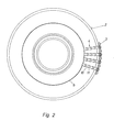
- FIG 2 shows the inside of the wheel shown in Figure 1. Only a few of the bumper strips 4 distributed over the entire circumference are shown.
- the strands 4 extend from the inner edge of the running net 3 in the area of the inner tire edge up to the steel tether 6.
- Each shock absorber strand consists of several shock absorbers 10 as well as hooked-on side connecting pins 11.
- Retaining chain may be provided instead of the steel tether which is preferably to be used.
- the shock absorber strands 4 and 5 are arranged so close to one another and are of such a length that good protection of the tire sidewalls is ensured.
- the shock absorbers have wear profiles at least on their outer sides.
- the bumper can also wear wear profiles on both sides, so that the bumper can be used after turning if necessary, if one side is worn or damaged.
- FIG 3 shows the outside of the wheel shown in Figure 1.
- the shock absorber strands 5 distributed over the circumference are shown in the drawing.
- several shock absorber strands 5, in this exemplary embodiment two are connected by means of a yoke-like bridging element 12 , in the middle of which a coil spring 7 is hooked.
- transition connection brackets 13 are provided in the transition area between the edges of the running net 3 and the lateral bumper strands.
- the running network consists of the basic bodies 100 shown in the upper part of FIG. 4 /, which have an approximately rectangular plan, and in which holding brackets 200 are provided on opposite sides at right angles to the basic body level.
- the base bodies 100 are joined to form a composite by means of connecting brackets 300 oriented perpendicular to the holding brackets 200.
- the connecting brackets 300 oriented perpendicular to the holding brackets 200 are not provided on the edge of the running net, but rather special connecting brackets 400 which, like the holding brackets 200, are oriented perpendicular to the plane defined by the base body 100.
- the transition connection bilge 13 is guided through the pair of brackets 200, 400 oriented perpendicular to it. Then the bumper 10 and side connector bracket 11 alternately connect to the transition connector bracket 13 to form a bumper beam 4 or 5.
- Figures 5 to 7 show different views of a bumper 10.
- the bumper 10 is plate-shaped according to the drawing, it is preferably a drop-forged steel part.
- a wear profile 14 is formed on the outside of the bumper 10.
- Each bumper 10 has a through opening 15 with a recess 16 which does not extend to the side edges of the bumper 10 and which forms stops 17 in its lateral end regions.
- FIGS. 8 and 9 The connection between a bumper 10 and a side connection bracket 11 or also a transition connection bracket 13 is illustrated in FIGS. 8 and 9.
- the side connection bracket 11 shown there consists of round steel. It is bent in such a way that its two ends form a hooking gap 18, the hooking gap 18 being laterally delimited by two spaced-apart, annular collar-like projections 19 of the side connection bit 11.
- the transition connection brackets 13 are bent somewhat differently from the side connection brackets 11, but have in particular As for the area of the hooking gap, the same structure.
- the side connecting bracket 11 is inserted into the bumper 10 via the narrow point 20 of the bumper 10 shown in FIG. 8 below, the through the bumper and the side connector bracket defined planes according to FIG. 9 are approximately perpendicular to one another. It can be seen from FIG. 9 that a flattened portion 22 arranged approximately perpendicular to the plane of the side connection bracket 11 enables the side connection bracket to be displaced in the through opening 15. After the side connecting bar is slid 11 at that end of the through hole 15 where the recess 16 is located, the side connecting bracket 11 is rotated according to the indicated in FIG 9 arrow P 90 0 so that the side connecting bracket and the bumpers are located approximately in one plane. Lateral slipping of the two parts against one another is not possible because the collar-like lugs 19 rest against the stops 17 of the recess 16.
- the individual parts of the chain can be dimensioned differently depending on the tire size and accordingly the chain size.
- the side connection brackets 11 described above have a diameter of approximately 12 mm
- the impact deflectors 10 have a length of approximately 75 mm and a maximum width of approximately 50 mm.
- the thickness of the bumper 10 including the wear profile is approximately 35 mm at the thickest point.
- the weak point 20 is dimensioned according to a hooking gap from here preferably about 18 mm so that the side connection bracket 11 can be hooked in without difficulty.
- FIGS. 10 and 11 illustrate how the last bumper 10 of a bumper strand 4 is fixed to the steel tether 6 on the inside of the pipe.
- a thimble 24 for example made of sheet iron, is clamped onto the tether 6. With the thimble, the piece that penetrates the bumper 10 Retaining rope 6 then still a slightly smaller diameter than the passage opening 15 in the lower region of the bumper 10, that is in the region of the weak point 20 where the rope passes through the bumper 10.
- the impact deflector 10 can roll back and forth on the tether when the tire and the chain move, so that there is hardly any wear.
- Two retaining lugs 25 are bent outwards from the material of the thimble 24. The distance between the retaining lugs 25 is dimensioned such that the area of the impact deflector 10 which engages there fits precisely between the retaining lugs so that the impact deflector cannot move in the longitudinal direction of the tether 6.
- Figure 12 shows in detail the connection of two shock absorbers 10 located at the end of two shock absorber strands 5 with a helical spring 7.
- the yoke-like bridging member 12 penetrates with its two arms a passage opening 15 of a shock absorber 10, so that the shock absorbers 10 are each in a bulge 26 of the bridging member 12 are fixed.
- a projecting central part 27 of the bridging member has a hole 28 into which a hook 29 provided at one end of the coil spring 7 engages.
- a helical spring 7 is not hooked into each bridging member 12, but two adjacent bridging members 12 are first connected by means of a further bridging member 30 with end hooks 31 attached to them, and the hook 29 of the helical spring 7 is einreha kt in a hole 32 in the bridging member 30.
- Such a solution is recommended if the diameter of the tire is not very large, because otherwise the other ends of the coil springs 7, that is to say the axles, do not have enough space next to it own each other.
- the advantage of this embodiment is that the chain can be tensioned or retightened very quickly because fewer springs are to be tensioned.
- FIG. 14 shows the connection of the last impact deflector 10 of a shock deflector strand 5 with the retaining ring 9.
- the coil spring 7 is attached directly to the retaining ring 9.
- the retaining ring 9 has a U-shaped cross section.
- the hook 29 ' provided on the axial end of the helical spring 7 engages around a bolt 33 arranged approximately perpendicular to the transverse extent of the holding tire 9, the hook 29' passing through the holding ring 9 in the region of two bores 34.
- the tensioning arrangement shown in FIG. 14 has a wear and tension indicator, which consists of a rod 35 fastened to the retaining ring 9 and projecting radially outward therefrom, an arrow 36 attached to its upper end and a marking 37 provided on the helical spring 7.
- a wear and tension indicator which consists of a rod 35 fastened to the retaining ring 9 and projecting radially outward therefrom, an arrow 36 attached to its upper end and a marking 37 provided on the helical spring 7.
- the screw spring 7 shortens, with the result that the marking 37 on the coil spring approaches the arrow 36.
- the chain must be retensioned, which may be done by removing individual chain links from the chain mesh.
- the wear and tension indicator can also be designed differently, for example the rod 35 can be arranged next to the coil spring 7, or there can be an indicator rod on the last impact deflector 10 of the bumper strip 5 may be attached.
- the axial end of the coil spring 7 with the hook 29 is not hooked directly into the retaining ring 9, but rather into an eyelet 38 of the adjusting element 8.
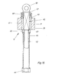
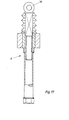
- FIGS. 16 and 17 show a longitudinal sectional view of an embodiment of the adjusting element 8 according to the invention.
- a plurality of sleeves 39 of which one is shown in FIG.
- the sleeve 39 has an inner guide opening 40 of non-circular, preferably square cross section, in which a bolt 41, which has a corresponding cross section in the region of the guide opening 40, is arranged so as to be displaceable in the radial direction of the wheel.
- the diameter of the lower bolt part is somewhat smaller than in the upper bolt part, and in the lower bolt part an external thread 42 is provided which is in engagement with an internal thread 43 of a sleeve 44.
- the sleeve 44 has a reinforced edge 45, the end face of which rests on the lower end face of the guide sleeve 39 and, moreover, forms a limit stop for the upper part of the bolt 41, so that the latter cannot move further downward. as shown in Figure 16.
- a pneumatic or electrical turning tool is preferably attached to the hexagon nut 48 located at the lower end of the sleeve 44, a specific torque being able to be set on the tool. This torque is then in a certain ratio to the preload in the coil springs.
- the invention is not restricted to the exemplary embodiments described above, but various modifications are still possible without deviating from the basic idea of the invention.
- the setting element described last it can be provided, for example, that the eyelet 38 is designed such that two hooks 29 'of two helical springs 7 can be hooked into it. This can be particularly recommended for tires with not too large diameters, so that the space available on the retaining ring 9 is sufficient for all setting elements.
Landscapes
- Engineering & Computer Science (AREA)
- Mechanical Engineering (AREA)
- Tires In General (AREA)
- Immobilizing And Processing Of Enzymes And Microorganisms (AREA)
- Chemical Or Physical Treatment Of Fibers (AREA)
- Lock And Its Accessories (AREA)
- Vibration Dampers (AREA)
Priority Applications (3)
| Application Number | Priority Date | Filing Date | Title |
|---|---|---|---|
| DE8282100479T DE3274089D1 (en) | 1982-01-23 | 1982-01-23 | Anti-slip chains for vehicle tyres |
| EP82100479A EP0084580B1 (fr) | 1982-01-23 | 1982-01-23 | Chaîne antidérapante pour pneumatiques |
| AT82100479T ATE23295T1 (de) | 1982-01-23 | 1982-01-23 | Reifen- und gleitschutzkette. |
Applications Claiming Priority (1)
| Application Number | Priority Date | Filing Date | Title |
|---|---|---|---|
| EP82100479A EP0084580B1 (fr) | 1982-01-23 | 1982-01-23 | Chaîne antidérapante pour pneumatiques |
Publications (2)
| Publication Number | Publication Date |
|---|---|
| EP0084580A1 true EP0084580A1 (fr) | 1983-08-03 |
| EP0084580B1 EP0084580B1 (fr) | 1986-11-05 |
Family
ID=8188836
Family Applications (1)
| Application Number | Title | Priority Date | Filing Date |
|---|---|---|---|
| EP82100479A Expired EP0084580B1 (fr) | 1982-01-23 | 1982-01-23 | Chaîne antidérapante pour pneumatiques |
Country Status (3)
| Country | Link |
|---|---|
| EP (1) | EP0084580B1 (fr) |
| AT (1) | ATE23295T1 (fr) |
| DE (1) | DE3274089D1 (fr) |
Cited By (2)
| Publication number | Priority date | Publication date | Assignee | Title |
|---|---|---|---|---|
| DE3219911A1 (de) * | 1982-05-27 | 1983-12-08 | Heinz 4600 Dortmund Asbeck | Netzstruktur |
| AT380209B (de) * | 1983-08-22 | 1986-04-25 | Pengg Walenta Ketten | Spanneinrichtung fuer reifenketten |
Citations (5)
| Publication number | Priority date | Publication date | Assignee | Title |
|---|---|---|---|---|
| DE195916C (fr) * | 1905-07-05 | |||
| FR356684A (fr) * | 1904-11-02 | 1905-12-06 | Isidore Clifford | Perfectionnements aux bandages des roues d'automobiles et d'autres véhicules |
| FR535143A (fr) * | 1920-05-10 | 1922-04-10 | Protecteurs pour bandages pneumatiques | |
| US2970632A (en) * | 1959-05-28 | 1961-02-07 | Simon F Kuc | Vehicle wheel chain |
| DE2824912A1 (de) * | 1978-06-07 | 1979-12-20 | Georg Geiss | Schnee und eiskette |
-
1982
- 1982-01-23 DE DE8282100479T patent/DE3274089D1/de not_active Expired
- 1982-01-23 EP EP82100479A patent/EP0084580B1/fr not_active Expired
- 1982-01-23 AT AT82100479T patent/ATE23295T1/de not_active IP Right Cessation
Patent Citations (5)
| Publication number | Priority date | Publication date | Assignee | Title |
|---|---|---|---|---|
| FR356684A (fr) * | 1904-11-02 | 1905-12-06 | Isidore Clifford | Perfectionnements aux bandages des roues d'automobiles et d'autres véhicules |
| DE195916C (fr) * | 1905-07-05 | |||
| FR535143A (fr) * | 1920-05-10 | 1922-04-10 | Protecteurs pour bandages pneumatiques | |
| US2970632A (en) * | 1959-05-28 | 1961-02-07 | Simon F Kuc | Vehicle wheel chain |
| DE2824912A1 (de) * | 1978-06-07 | 1979-12-20 | Georg Geiss | Schnee und eiskette |
Cited By (2)
| Publication number | Priority date | Publication date | Assignee | Title |
|---|---|---|---|---|
| DE3219911A1 (de) * | 1982-05-27 | 1983-12-08 | Heinz 4600 Dortmund Asbeck | Netzstruktur |
| AT380209B (de) * | 1983-08-22 | 1986-04-25 | Pengg Walenta Ketten | Spanneinrichtung fuer reifenketten |
Also Published As
| Publication number | Publication date |
|---|---|
| ATE23295T1 (de) | 1986-11-15 |
| EP0084580B1 (fr) | 1986-11-05 |
| DE3274089D1 (en) | 1986-12-11 |
Similar Documents
| Publication | Publication Date | Title |
|---|---|---|
| DE69513155T2 (de) | Anordnung zum schnellbefestigen von schneeketten an fahrzeugreifen | |
| DE3032670C2 (fr) | ||
| EP1711356B1 (fr) | Dispositif d'assemblage, sans l'aide d'outil, de deux maillons d'une chaine fermee, avec possibilite de reglage a des distances differentes, et/ou de reparation d'une chaine cassee | |
| EP0312636A1 (fr) | Dispositif anti-dérapage pour roues | |
| EP0084580B1 (fr) | Chaîne antidérapante pour pneumatiques | |
| DE102012102231A1 (de) | Gleitschutzkette mit seitenstabilen Führungsketten | |
| DE2631147B2 (de) | Gleitschutzvorrichtung für Fahrzeugräder | |
| DE2545310C2 (de) | Gleitschutzkette für Kraftfahrzeugreifen | |
| EP3272560B1 (fr) | Chaîne pour pneu ayant un brin de chaîne à 45° | |
| DE1288934B (de) | Gleitschutzkette mit einem in der Grundform zickzackfoermigen Laufnetz | |
| EP2142388B1 (fr) | Pneumatique de véhicule | |
| EP0274981B1 (fr) | Chaînes antidérapantes pour pneus de véhicules | |
| EP0084579A2 (fr) | Chaîne antidérapant pour véhicules à pneumatiques, spécialement pour machines lourdes pour le travail de la terre | |
| AT518564B1 (de) | Kette zur Montage an einem Fahrzeugreifen | |
| EP0911192B1 (fr) | Elément de fermeture de la chaíne de serrage d'une chaíne anti-dérapante | |
| DE102018104706A1 (de) | Auffahrschiene | |
| DE102018208325A1 (de) | Reifenkette, insbesondere für Doppel- oder Mehrachsaggregate, wie beispielsweise Bogie-Achsen | |
| DE102019200350B4 (de) | Nutzfahrzeugreifenkette, Nutzfahrzeugreifen und Stollenplatte für eine Nutzfahrzeugreifenkette | |
| AT413202B (de) | Stützglied zur verwendung bei einer reifenkette und reifenkette | |
| DE102023108370A1 (de) | Plattenband mit wenigstens einem ein Formschlusselement aufweisenden Traktionsvorsprung | |
| EP3023272B1 (fr) | Articulation de chaîne dotée d'ergots et pièce à trois éléments et chaîne de pneu en étant dotée | |
| CH629706A5 (de) | Reifenkette. | |
| DE202022100913U1 (de) | Felgenadapter zur Befestigung einer selbstzentrierenden Gleitschutzkette an einer Fahrzeugfelge mit einem axial nach außen gewölbten Felgentopf | |
| EP2765013B1 (fr) | Chaîne antipatinage pour roues jumelées | |
| DE102020208691A1 (de) | Laufflächenspannelement für eine Reifenkette und Reifenkette |
Legal Events
| Date | Code | Title | Description |
|---|---|---|---|
| PUAI | Public reference made under article 153(3) epc to a published international application that has entered the european phase |
Free format text: ORIGINAL CODE: 0009012 |
|
| 17P | Request for examination filed |
Effective date: 19821015 |
|
| AK | Designated contracting states |
Designated state(s): AT BE CH DE FR GB IT LI LU NL SE |
|
| GRAA | (expected) grant |
Free format text: ORIGINAL CODE: 0009210 |
|
| AK | Designated contracting states |
Kind code of ref document: B1 Designated state(s): AT BE CH DE FR GB IT LI LU NL SE |
|
| REF | Corresponds to: |
Ref document number: 23295 Country of ref document: AT Date of ref document: 19861115 Kind code of ref document: T |
|
| REF | Corresponds to: |
Ref document number: 3274089 Country of ref document: DE Date of ref document: 19861211 |
|
| ITF | It: translation for a ep patent filed | ||
| PG25 | Lapsed in a contracting state [announced via postgrant information from national office to epo] |
Ref country code: LU Free format text: LAPSE BECAUSE OF NON-PAYMENT OF DUE FEES Effective date: 19870131 |
|
| ET | Fr: translation filed | ||
| PLBE | No opposition filed within time limit |
Free format text: ORIGINAL CODE: 0009261 |
|
| STAA | Information on the status of an ep patent application or granted ep patent |
Free format text: STATUS: NO OPPOSITION FILED WITHIN TIME LIMIT |
|
| 26N | No opposition filed | ||
| PGFP | Annual fee paid to national office [announced via postgrant information from national office to epo] |
Ref country code: AT Payment date: 19881229 Year of fee payment: 8 |
|
| PGFP | Annual fee paid to national office [announced via postgrant information from national office to epo] |
Ref country code: SE Payment date: 19890102 Year of fee payment: 8 |
|
| PGFP | Annual fee paid to national office [announced via postgrant information from national office to epo] |
Ref country code: DE Payment date: 19890123 Year of fee payment: 8 |
|
| PGFP | Annual fee paid to national office [announced via postgrant information from national office to epo] |
Ref country code: CH Payment date: 19890126 Year of fee payment: 8 |
|
| PG25 | Lapsed in a contracting state [announced via postgrant information from national office to epo] |
Ref country code: FR Effective date: 19890131 |
|
| PGFP | Annual fee paid to national office [announced via postgrant information from national office to epo] |
Ref country code: NL Payment date: 19890131 Year of fee payment: 11 Ref country code: GB Payment date: 19890131 Year of fee payment: 8 Ref country code: BE Payment date: 19890131 Year of fee payment: 8 |
|
| PG25 | Lapsed in a contracting state [announced via postgrant information from national office to epo] |
Ref country code: GB Effective date: 19900123 Ref country code: AT Effective date: 19900123 |
|
| PG25 | Lapsed in a contracting state [announced via postgrant information from national office to epo] |
Ref country code: SE Effective date: 19900124 |
|
| PG25 | Lapsed in a contracting state [announced via postgrant information from national office to epo] |
Ref country code: LI Effective date: 19900131 Ref country code: CH Effective date: 19900131 Ref country code: BE Effective date: 19900131 |
|
| BERE | Be: lapsed |
Owner name: ASBECK HEINZ Effective date: 19900131 |
|
| PG25 | Lapsed in a contracting state [announced via postgrant information from national office to epo] |
Ref country code: NL Effective date: 19900801 |
|
| NLV4 | Nl: lapsed or anulled due to non-payment of the annual fee | ||
| GBPC | Gb: european patent ceased through non-payment of renewal fee | ||
| REG | Reference to a national code |
Ref country code: CH Ref legal event code: PL |
|
| PG25 | Lapsed in a contracting state [announced via postgrant information from national office to epo] |
Ref country code: DE Effective date: 19901002 |
|
| REG | Reference to a national code |
Ref country code: FR Ref legal event code: ST |
|
| EUG | Se: european patent has lapsed |
Ref document number: 82100479.3 Effective date: 19901106 |