EP0084741A2 - Vorrichtung zum Einsperren von Zuchtgeflügel während der Besamung - Google Patents
Vorrichtung zum Einsperren von Zuchtgeflügel während der Besamung Download PDFInfo
- Publication number
- EP0084741A2 EP0084741A2 EP82400786A EP82400786A EP0084741A2 EP 0084741 A2 EP0084741 A2 EP 0084741A2 EP 82400786 A EP82400786 A EP 82400786A EP 82400786 A EP82400786 A EP 82400786A EP 0084741 A2 EP0084741 A2 EP 0084741A2
- Authority
- EP
- European Patent Office
- Prior art keywords
- birds
- board
- fixed
- adjustable
- restraining
- Prior art date
- Legal status (The legal status is an assumption and is not a legal conclusion. Google has not performed a legal analysis and makes no representation as to the accuracy of the status listed.)
- Granted
Links
Images


Classifications
-
- A—HUMAN NECESSITIES
- A61—MEDICAL OR VETERINARY SCIENCE; HYGIENE
- A61D—VETERINARY INSTRUMENTS, IMPLEMENTS, TOOLS, OR METHODS
- A61D3/00—Arrangements for supporting or fettering animals for veterinary purposes
-
- A—HUMAN NECESSITIES
- A01—AGRICULTURE; FORESTRY; ANIMAL HUSBANDRY; HUNTING; TRAPPING; FISHING
- A01K—ANIMAL HUSBANDRY; AVICULTURE; APICULTURE; PISCICULTURE; FISHING; REARING OR BREEDING ANIMALS, NOT OTHERWISE PROVIDED FOR; NEW BREEDS OF ANIMALS
- A01K37/00—Constraining birds, e.g. wing clamps
Definitions
- the present invention relates to a device for keeping high birds, used for insemination of female birds such as hens, guinea fowl, turkeys and / or for collecting semen from males.
- an object of the present invention is to provide a device for restraining birds which leaves them close to their cages, supporting them and now to allow the operator to intervene. with both hands to harvest or inseminate. Said restraining device must also allow the operator to move along the batteries at a suitable distance and at the various levels necessary.
- the volatile retaining and guiding member is a board in the form of a slide arranged below the volatile containment means and whose inclination is adjustable relative to the carriage.
- the operator having placed the carriage in position in front of a battery, grasps a bird by its legs, places it against the board and fixes it by its legs in the means of restraint, practices insemination and unblocks said said means, the bird then falling into its cage without any help from the operator.
- the board comprises lateral flanges and slightly recessed imprints, provided in a number equal to that of the means for restraining the birds, the flanges and / or the imprints serving to guide the birds falling under the action of their own weight when released from the means of restraint.
- the containment means for each bird are suitably formed by vertical clamps, one of which is fixed and the other of which is movable in an adjustable support on a horizontal angle fixed to the board.
- the clamps are constituted by a fixed shoe secured to the adjustable support and by a shoe movable in a vertical plane around a horizontal axis under the action of a return spring, the movable shoe comprising a recessed part such that, in its closed position when it is applied against the fixed shoe, it delimits with the latter a roughly pear-shaped opening in vertical cross section.
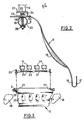
- the carriage 1 can move in front of the superimposed batteries 8 of individual cages 9 containing the birds - hens for example - parallel to said cages being guided by castors 10 fixed on the extensions of horizontal arms 11 mounted at the top of the carriage 1
- the latter further comprises a plate 12 suitable for carrying the operator and which can be placed at different heights, for example on lateral uprights, such as 13, adjustable in height in a conventional manner not shown on the vertical uprights 3, which allows the operator to be seated or standing depending on the level of the battery concerned.
- FIGS. 2 and 3 for the sake of clarity of the drawing, only the member 6 for retaining and guiding the volatiles and means of restraint of the latter, which are integral with it as will be described below, has been shown.
- the member 6 for retaining and guiding the birds is constituted by a curved board having a shape of a slide, the central part of which can have indentations 15 (in dotted lines) slightly hollow allowing better support and positioning of the birds and whose edge lower 16 is vertical (solid line) or may include a kind of gutter 17, for example for collecting the droppings of birds.
- the board 6 further comprises removable lateral flanges 18, fixed to the lateral sides of the board by tongues 19 penetrating into holes 20 of said board whose width corresponds to a determined number (here four) of birds.
- This clipboard is disposed below the means 14 for containing the volatiles, described below in detail, and which are fixed in an adjustable manner laterally in a slide 21 of an elongated and flat horizontal angle 22 secured in a conventional manner not shown, of the horizontal part 23 of the board 6.
- the restraining means 14 are fixed to the angle iron 22 by threaded rods 24, situated at their lower part and passing through the slide 21, and nuts 25.
- the angle 22 is made integral with the horizontal part of the board 6, by fixing members such as bolts 26 passing through holes not shown formed in the preferably curved ends (Fig. 3) of the angle and elongated slots 27 formed in the board 6, so that the latter can be adjusted in position relative to the support tube 5 by means of the tightening of knurled nuts 28.
- the tube 5 may comprise, to the right of each bolt 26, an upper hole 29 of a diameter just sufficient for the passage of the rod of the bolt 26, while the lower hole 30 is in the form of an elongated lumen, for example, oval.
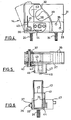
- These means 14 essentially consist of a clamp 31 fixed in the form of a vertical shoe or solid pad and of a movable clamp 32 in the form of a vertical shoe or solid pad, said clamps preferably being made of a material which does not injure volatiles, such as rubber.
- the fixed clamp 31 is secured to a support 33 in the form of a U-shaped angle iron, in cross section having lateral flanges 34, of a height less than that of the clamps 31, 32, using bolts 35.
- the movable clamp 32 can pivot around a horizontal axis 36 fixed in free rotation at the other end of the support 33, being retained by a pin 37, between a closed position (shown in solid lines) and an open position (shown in dashed line in FIG. 4), said clamp flowing freely between the flanges 34 of the support 33.
- the movable clamp 32 has a transverse recess 38 of suitable flared shape, while the surface of the clamp 31 facing the clamp 32 has a slightly curved profile 39.
- the lower edge of the clamp 32, located below the opening 38, has a shape adapted to that of profile 39, so that in the closed state, the two clamps delimit an opening preferably in the shape of a pear in cross section making it possible to accommodate the two legs of a bird.
- the restraining means 14 comprise a return spring 40 used to permanently push back in the open position the clamp 32 which is partially wound around the axis 36 and comprises an upper branch 41, of which a horizontal bent part 42 is integral rigid lateral flanges 43, enclosing the clamp 32 and of which the latter: is integral, and a lower branch 44 fixed in one of the flanges 33, between which the clamp 32 pivots.
- a return spring 40 used to permanently push back in the open position the clamp 32 which is partially wound around the axis 36 and comprises an upper branch 41, of which a horizontal bent part 42 is integral rigid lateral flanges 43, enclosing the clamp 32 and of which the latter: is integral, and a lower branch 44 fixed in one of the flanges 33, between which the clamp 32 pivots.
- said containment means 14 provided for each bird comprises a system 45 for locking the movable clamp 32 in the closed position.
- This system shown in more detail in Figure 7, consists of a rod 46 mounted with the possibility of longitudinal sliding in translation perpendicular to the clamps 31, 32, in a molded block 47 fixed to the support 33 of the clamps by means of bolts 48.
- the connecting rod 46 has an internal end 49 projecting in the form of a stud engaging in the closed state in a corresponding cavity 50 formed in the lateral flange 43 of the movable clamp 32, being subjected to the permanent action of a pressure spring 51 interposed between a shoulder 52 of the link and the bottom 53 of the molded block.
- FIG. 8 shows an alternative embodiment of the locking system of the movable clamp, which here consists of a link 55, the inner end of which comprises a hemispherical cavity 56, capable of partially accommodating a ball 57 partly U housed in a corresponding cavity 58 formed in the flange 43, said ball being retained by appropriate means not shown in the flange 43 or which can even be replaced, as well as the cavity 58 by a simple hemispherical bulge (not shown) in the flange 43.
- the mobile clamp 32 is released in the same manner as above by pulling on the ring 53.
- FIG. 10 the case is shown where the means 14 for retaining volatile dice are joined together, at the outer ends of their links 63, 64, by a bar 65 articulated by any suitable known means, allowing either to release two volatiles simultaneously, or to release one, while keeping the other in the second compression system.
- the board 6 could not be rigidly secured to the angle 22, but be articulated by any known suitable means, the adjustment in the inclined position then being carried out using devices (not shown) screwable for example on the uprights of the carriage 1.
- the clamp 31 can be adjusted in translation relative to the clamp 32, angularly movable, in order to vary the width of the recess 38 to adapt the latter to the size of the legs of the birds.
- This adjustment can be carried out easily by providing lights 33 in the support allowing the adjustment of the clamp 31 which could thus be fixed by bolts in any relative position relative to the clamp 32.
Landscapes
- Life Sciences & Earth Sciences (AREA)
- Health & Medical Sciences (AREA)
- Veterinary Medicine (AREA)
- Animal Husbandry (AREA)
- Environmental Sciences (AREA)
- Engineering & Computer Science (AREA)
- Biodiversity & Conservation Biology (AREA)
- Birds (AREA)
- Wood Science & Technology (AREA)
- Zoology (AREA)
- Animal Behavior & Ethology (AREA)
- General Health & Medical Sciences (AREA)
- Public Health (AREA)
- Catching Or Destruction (AREA)
- Housing For Livestock And Birds (AREA)
Applications Claiming Priority (2)
| Application Number | Priority Date | Filing Date | Title |
|---|---|---|---|
| FR8201254A FR2520191A1 (fr) | 1982-01-27 | 1982-01-27 | Dispositif de contention d'oiseaux eleves, servant a l'insemination et a la recolte de semence de ces derniers |
| FR8201254 | 1982-01-27 |
Publications (3)
| Publication Number | Publication Date |
|---|---|
| EP0084741A2 true EP0084741A2 (de) | 1983-08-03 |
| EP0084741A3 EP0084741A3 (en) | 1983-08-10 |
| EP0084741B1 EP0084741B1 (de) | 1985-10-16 |
Family
ID=9270367
Family Applications (1)
| Application Number | Title | Priority Date | Filing Date |
|---|---|---|---|
| EP82400786A Expired EP0084741B1 (de) | 1982-01-27 | 1982-04-29 | Vorrichtung zum Einsperren von Zuchtgeflügel während der Besamung |
Country Status (6)
| Country | Link |
|---|---|
| US (1) | US4463707A (de) |
| EP (1) | EP0084741B1 (de) |
| JP (1) | JPS58165839A (de) |
| CA (1) | CA1171745A (de) |
| DE (1) | DE3266901D1 (de) |
| FR (1) | FR2520191A1 (de) |
Families Citing this family (4)
| Publication number | Priority date | Publication date | Assignee | Title |
|---|---|---|---|---|
| DE102009041238A1 (de) * | 2009-09-11 | 2011-03-24 | Krones Ag | Vorrichtung und Verfahren zum Beladen eines Gebindespeichers |
| CN116509590B (zh) * | 2023-04-24 | 2023-12-19 | 江苏省家禽科学研究所 | 一种水禽养殖人工授精装置 |
| CN116509595B (zh) * | 2023-05-29 | 2026-04-17 | 安徽农业大学 | 一种羊人工采精用辅助装置 |
| FR3157066B1 (fr) * | 2023-12-22 | 2025-11-28 | Agritubel | Barrière de sécurisation pour intervention sur bovin |
Family Cites Families (6)
| Publication number | Priority date | Publication date | Assignee | Title |
|---|---|---|---|---|
| US2484088A (en) * | 1945-11-13 | 1949-10-11 | Dale A Hayes | Testing and operating table for fowls |
| US2966884A (en) * | 1958-07-30 | 1961-01-03 | Naraghi Hashem | Egg gathering apparatus for a poultry cage battery |
| US3132735A (en) * | 1960-12-19 | 1964-05-12 | Norman P Nilsen | Apparatus for processing eggs |
| US3774578A (en) * | 1972-12-15 | 1973-11-27 | A Randolph | Poultry handling apparatus |
| US3880122A (en) * | 1972-12-15 | 1975-04-29 | Arthur J Randolph | Poultry inseminator |
| US3872869A (en) * | 1973-08-02 | 1975-03-25 | Arthur J Randolph | Poultry semen collecting apparatus |
-
1982
- 1982-01-27 FR FR8201254A patent/FR2520191A1/fr active Granted
- 1982-04-29 EP EP82400786A patent/EP0084741B1/de not_active Expired
- 1982-04-29 DE DE8282400786T patent/DE3266901D1/de not_active Expired
- 1982-05-31 CA CA000404105A patent/CA1171745A/en not_active Expired
- 1982-06-02 US US06/384,436 patent/US4463707A/en not_active Expired - Lifetime
-
1983
- 1983-01-26 JP JP58012071A patent/JPS58165839A/ja active Granted
Also Published As
| Publication number | Publication date |
|---|---|
| DE3266901D1 (en) | 1985-11-21 |
| FR2520191A1 (fr) | 1983-07-29 |
| US4463707A (en) | 1984-08-07 |
| FR2520191B1 (de) | 1984-04-20 |
| JPS6136934B2 (de) | 1986-08-21 |
| JPS58165839A (ja) | 1983-09-30 |
| EP0084741A3 (en) | 1983-08-10 |
| CA1171745A (en) | 1984-07-31 |
| EP0084741B1 (de) | 1985-10-16 |
Similar Documents
| Publication | Publication Date | Title |
|---|---|---|
| EP0536057B1 (de) | Verfahren und Vorrichtung zum Erklimmen eines Seiles | |
| EP0084741B1 (de) | Vorrichtung zum Einsperren von Zuchtgeflügel während der Besamung | |
| FR2833481A1 (fr) | Appareil de transfert d'une personne | |
| FR2620323A1 (fr) | Dispositif pour enfiler un vetement | |
| EP0011563A1 (de) | Vorrichtung zum Festhalten des von einem Schlachttier getrennten Kopfes | |
| FR2833807A1 (fr) | Dispositif et installation de gavage de volailles | |
| FR2690043A1 (fr) | Procédé et dispositif de manutention et de transport de régimes de bananes en vue de leur conditionnement. | |
| FR2565781A3 (fr) | Cage de contention pour bovins | |
| FR2595204A1 (fr) | Appareil portable pour la contention des bovins | |
| FR2491311A1 (fr) | Siege de travail, notamment pour agriculteur | |
| EP0248741B1 (de) | Behälter zum Aufbewahren von Langleinen | |
| EP4258863B1 (de) | Selbsfang-fressgitter | |
| FR2662582A1 (fr) | Dispositif de decrochage de demi-carcasses convoyees par tinets dans une chaine d'abattoir. | |
| EP0060798A1 (de) | Muskeltrainingsgerät | |
| FR2612281A1 (fr) | Support automatique, notamment pour appareil de prise de vues | |
| WO1995020867A1 (fr) | Dispositif de repiquage rapide de vegetaux | |
| EP0140750A2 (de) | Vorrichtung zum Betäuben von Schlachtvieh durch elektrische Entladung | |
| FR2599586A1 (fr) | Dispositif de capture d'animaux domestiques | |
| FR2729543A1 (fr) | Element d'orientation et de positionnement pour plante a tige | |
| FR2809949A1 (fr) | Dispositif d'insemination artificielle, en particulier pour truie | |
| FR2662731A1 (fr) | Dispositif pour l'elingage de panneaux de coffrage. | |
| FR2730386A1 (fr) | Dispositif pour le transfert automatique des volailles entre deux convoyeurs d'une installation d'abattage | |
| FR2487194A1 (fr) | Table de kinesitherapie | |
| FR2722648A1 (fr) | Olailles dispositif d'alimentation d'animaux tels que des v | |
| FR3157066A1 (fr) | Barrière de sécurisation pour intervention sur bovin |
Legal Events
| Date | Code | Title | Description |
|---|---|---|---|
| PUAI | Public reference made under article 153(3) epc to a published international application that has entered the european phase |
Free format text: ORIGINAL CODE: 0009012 |
|
| PUAL | Search report despatched |
Free format text: ORIGINAL CODE: 0009013 |
|
| AK | Designated contracting states |
Designated state(s): BE DE GB IT NL SE |
|
| AK | Designated contracting states |
Designated state(s): BE DE GB IT NL SE |
|
| 17P | Request for examination filed |
Effective date: 19830901 |
|
| ITF | It: translation for a ep patent filed | ||
| GRAA | (expected) grant |
Free format text: ORIGINAL CODE: 0009210 |
|
| AK | Designated contracting states |
Designated state(s): BE DE GB IT NL SE |
|
| REF | Corresponds to: |
Ref document number: 3266901 Country of ref document: DE Date of ref document: 19851121 |
|
| PLBE | No opposition filed within time limit |
Free format text: ORIGINAL CODE: 0009261 |
|
| STAA | Information on the status of an ep patent application or granted ep patent |
Free format text: STATUS: NO OPPOSITION FILED WITHIN TIME LIMIT |
|
| 26N | No opposition filed | ||
| ITTA | It: last paid annual fee | ||
| EAL | Se: european patent in force in sweden |
Ref document number: 82400786.8 |
|
| PGFP | Annual fee paid to national office [announced via postgrant information from national office to epo] |
Ref country code: SE Payment date: 19960327 Year of fee payment: 15 |
|
| PGFP | Annual fee paid to national office [announced via postgrant information from national office to epo] |
Ref country code: BE Payment date: 19960412 Year of fee payment: 15 |
|
| PGFP | Annual fee paid to national office [announced via postgrant information from national office to epo] |
Ref country code: GB Payment date: 19960422 Year of fee payment: 15 |
|
| PGFP | Annual fee paid to national office [announced via postgrant information from national office to epo] |
Ref country code: DE Payment date: 19960429 Year of fee payment: 15 |
|
| PGFP | Annual fee paid to national office [announced via postgrant information from national office to epo] |
Ref country code: NL Payment date: 19960529 Year of fee payment: 15 |
|
| PG25 | Lapsed in a contracting state [announced via postgrant information from national office to epo] |
Ref country code: GB Effective date: 19970429 |
|
| PG25 | Lapsed in a contracting state [announced via postgrant information from national office to epo] |
Ref country code: SE Effective date: 19970430 Ref country code: BE Effective date: 19970430 |
|
| BERE | Be: lapsed |
Owner name: CASSOU MAURICE Effective date: 19970430 Owner name: CASSOU BERTRAND Effective date: 19970430 Owner name: CASSOU ROBERT Effective date: 19970430 |
|
| PG25 | Lapsed in a contracting state [announced via postgrant information from national office to epo] |
Ref country code: NL Effective date: 19971101 |
|
| GBPC | Gb: european patent ceased through non-payment of renewal fee |
Effective date: 19970429 |
|
| PG25 | Lapsed in a contracting state [announced via postgrant information from national office to epo] |
Ref country code: DE Free format text: LAPSE BECAUSE OF NON-PAYMENT OF DUE FEES Effective date: 19980101 |
|
| NLV4 | Nl: lapsed or anulled due to non-payment of the annual fee |
Effective date: 19971101 |
|
| EUG | Se: european patent has lapsed |
Ref document number: 82400786.8 |