EP0084786A2 - Disposition pour chambre de refroidissement, séparateur et chaudière à chaleurs perdues d'une installation de refroidissement à sec de coke - Google Patents
Disposition pour chambre de refroidissement, séparateur et chaudière à chaleurs perdues d'une installation de refroidissement à sec de coke Download PDFInfo
- Publication number
- EP0084786A2 EP0084786A2 EP83100119A EP83100119A EP0084786A2 EP 0084786 A2 EP0084786 A2 EP 0084786A2 EP 83100119 A EP83100119 A EP 83100119A EP 83100119 A EP83100119 A EP 83100119A EP 0084786 A2 EP0084786 A2 EP 0084786A2
- Authority
- EP
- European Patent Office
- Prior art keywords
- cooling
- waste heat
- heat boiler
- separators
- separator
- Prior art date
- Legal status (The legal status is an assumption and is not a legal conclusion. Google has not performed a legal analysis and makes no representation as to the accuracy of the status listed.)
- Granted
Links
Images


Classifications
-
- B—PERFORMING OPERATIONS; TRANSPORTING
- B01—PHYSICAL OR CHEMICAL PROCESSES OR APPARATUS IN GENERAL
- B01D—SEPARATION
- B01D45/00—Separating dispersed particles from gases or vapours by gravity, inertia, or centrifugal forces
- B01D45/04—Separating dispersed particles from gases or vapours by gravity, inertia, or centrifugal forces by utilising inertia
- B01D45/08—Separating dispersed particles from gases or vapours by gravity, inertia, or centrifugal forces by utilising inertia by impingement against baffle separators
-
- C—CHEMISTRY; METALLURGY
- C10—PETROLEUM, GAS OR COKE INDUSTRIES; TECHNICAL GASES CONTAINING CARBON MONOXIDE; FUELS; LUBRICANTS; PEAT
- C10B—DESTRUCTIVE DISTILLATION OF CARBONACEOUS MATERIALS FOR PRODUCTION OF GAS, COKE, TAR, OR SIMILAR MATERIALS
- C10B39/00—Cooling or quenching coke
- C10B39/02—Dry cooling outside the oven
-
- F—MECHANICAL ENGINEERING; LIGHTING; HEATING; WEAPONS; BLASTING
- F22—STEAM GENERATION
- F22B—METHODS OF STEAM GENERATION; STEAM BOILERS
- F22B1/00—Methods of steam generation characterised by form of heating method
- F22B1/02—Methods of steam generation characterised by form of heating method by exploitation of the heat content of hot heat carriers
- F22B1/18—Methods of steam generation characterised by form of heating method by exploitation of the heat content of hot heat carriers the heat carrier being a hot gas, e.g. waste gas such as exhaust gas of internal-combustion engines
- F22B1/1838—Methods of steam generation characterised by form of heating method by exploitation of the heat content of hot heat carriers the heat carrier being a hot gas, e.g. waste gas such as exhaust gas of internal-combustion engines the hot gas being under a high pressure, e.g. in chemical installations
- F22B1/1846—Methods of steam generation characterised by form of heating method by exploitation of the heat content of hot heat carriers the heat carrier being a hot gas, e.g. waste gas such as exhaust gas of internal-combustion engines the hot gas being under a high pressure, e.g. in chemical installations the hot gas being loaded with particles, e.g. waste heat boilers after a coal gasification plant
-
- F—MECHANICAL ENGINEERING; LIGHTING; HEATING; WEAPONS; BLASTING
- F22—STEAM GENERATION
- F22B—METHODS OF STEAM GENERATION; STEAM BOILERS
- F22B1/00—Methods of steam generation characterised by form of heating method
- F22B1/02—Methods of steam generation characterised by form of heating method by exploitation of the heat content of hot heat carriers
- F22B1/18—Methods of steam generation characterised by form of heating method by exploitation of the heat content of hot heat carriers the heat carrier being a hot gas, e.g. waste gas such as exhaust gas of internal-combustion engines
- F22B1/1869—Hot gas water tube boilers not provided for in F22B1/1807 - F22B1/1861
- F22B1/1876—Hot gas water tube boilers not provided for in F22B1/1807 - F22B1/1861 the hot gas being loaded with particles, e.g. dust
-
- Y—GENERAL TAGGING OF NEW TECHNOLOGICAL DEVELOPMENTS; GENERAL TAGGING OF CROSS-SECTIONAL TECHNOLOGIES SPANNING OVER SEVERAL SECTIONS OF THE IPC; TECHNICAL SUBJECTS COVERED BY FORMER USPC CROSS-REFERENCE ART COLLECTIONS [XRACs] AND DIGESTS
- Y02—TECHNOLOGIES OR APPLICATIONS FOR MITIGATION OR ADAPTATION AGAINST CLIMATE CHANGE
- Y02P—CLIMATE CHANGE MITIGATION TECHNOLOGIES IN THE PRODUCTION OR PROCESSING OF GOODS
- Y02P20/00—Technologies relating to chemical industry
- Y02P20/10—Process efficiency
- Y02P20/129—Energy recovery, e.g. by cogeneration, H2recovery or pressure recovery turbines
Definitions
- the invention relates to the arrangement of the cooling shaft, separator and waste heat boiler for dedusting and cooling circulating cooling gas used for dry coke cooling.
- the hot coke introduced into the cooling shaft from above is usually treated in countercurrent with the cooling gas rising from the bottom of the cooling shaft. It is practically inevitable that the cooling gas entrains coke dust particles when flowing through the hot coke. Since, as a rule, the cooling gas flows through a waste heat boiler to give off heat, it is advantageous to dedust the cooling gas before it enters the boiler. If no dedusting were provided, the dust would deposit in the boiler, which would lead to wear, blockages and poorer heat exchange conditions.
- the dedusting units are arranged spatially separated from the boiler in front of the boiler, which on the one hand leads to an increased space requirement for the overall system, particularly in the case of gravity separators.
- the degrees of separation are adversely affected by the fact that the gas stream to be discharged and falling down is traversed by the gas stream and entrained again.
- the use of cyclones in the hot cooling gas (approx. 800 ° C) is limited from an economic point of view due to the large gas volumes (approx. 15oo m 3 / t coke, m 3 at 0 ° C and 1, o13 bar).
- the invention is therefore based on the object to achieve a space-saving design by means of a suitable arrangement of cooling shaft, separator and waste heat boiler and to optimize the degree of separation of the separator by means of a cooling gas duct which avoids crossing the separated solid stream.
- two outlet channels for the hot cooling gas be provided on the cooling shaft, which lead to two separators arranged on both sides of the waste heat boiler.
- the entry of the cooling gas from the separators into the waste heat boiler is essentially perpendicular to the falling movement of the material separated in the separators.
- the separators can be attached to the waste heat boiler and formed by cooling walls of the waste heat boiler.
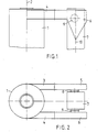
- FIG. 1 shows a side view of the arrangement according to the invention
- FIG. 2 shows a top view of this arrangement
- FIG. 3 shows a front view of another arrangement of separator and waste heat boiler
- FIG. 4 shows a side view of this arrangement.
- FIGS. 1 and 2 denotes the cooling shaft to which the hot coke is fed at 2 and in which the coke is acted upon in countercurrent with cooling gas flowing from bottom to top.
- This cooling gas leaves the cooling shaft at its upper end through two outlet channels 3 and 4, which lead to two separators 5 and 6 designed in the present case as impact separators.
- the separators are arranged on both sides of the waste heat boiler 7, to which they are connected by the connections 8 and 9.
- the cooling gas flows through the channels 3 and 4 into the separators 5 and 6 and from there into the waste heat boiler with a right-angled deflection.
- the separator does not take up the space between the cooling shaft and the waste heat boiler, but rather that the two proposed separators fill lateral void spaces which are given by the smaller dimensions of the waste heat boiler compared to the cooling shaft.
- cyclones can also be used. 3 and 4, the separators 12 and 13 are attached directly to the waste heat boiler 14, i.e. they are formed by the walls 15 of the boiler.
- the cooling gas inlets into the separators are designated 16 and 17.
- the arrows 18 illustrate the failure of the coke particles from the gas, which are withdrawn from the separator at 19 or 20.
- the cooling gas itself flows upwards (arrows 21) into the waste heat boiler. At 22, the tube bundles of the waste heat boiler are still indicated.
Landscapes
- Engineering & Computer Science (AREA)
- Chemical & Material Sciences (AREA)
- Mechanical Engineering (AREA)
- General Engineering & Computer Science (AREA)
- Sustainable Development (AREA)
- Sustainable Energy (AREA)
- Physics & Mathematics (AREA)
- Thermal Sciences (AREA)
- Combustion & Propulsion (AREA)
- Life Sciences & Earth Sciences (AREA)
- Chemical Kinetics & Catalysis (AREA)
- Materials Engineering (AREA)
- Oil, Petroleum & Natural Gas (AREA)
- Organic Chemistry (AREA)
- Coke Industry (AREA)
- Separating Particles In Gases By Inertia (AREA)
Priority Applications (1)
| Application Number | Priority Date | Filing Date | Title |
|---|---|---|---|
| AT83100119T ATE26994T1 (de) | 1982-01-27 | 1983-01-08 | Anordnung von kuehlschacht, abscheider und abhitzekessel einer kokstrockenkuehlanlage. |
Applications Claiming Priority (2)
| Application Number | Priority Date | Filing Date | Title |
|---|---|---|---|
| DE19823202573 DE3202573A1 (de) | 1982-01-27 | 1982-01-27 | Anordnung von kuehlschacht, abscheider und abhitzekessel einer kokstrockenkuehlanlage |
| DE3202573 | 1982-01-27 |
Publications (3)
| Publication Number | Publication Date |
|---|---|
| EP0084786A2 true EP0084786A2 (fr) | 1983-08-03 |
| EP0084786A3 EP0084786A3 (en) | 1985-01-09 |
| EP0084786B1 EP0084786B1 (fr) | 1987-05-06 |
Family
ID=6154027
Family Applications (1)
| Application Number | Title | Priority Date | Filing Date |
|---|---|---|---|
| EP83100119A Expired EP0084786B1 (fr) | 1982-01-27 | 1983-01-08 | Disposition pour chambre de refroidissement, séparateur et chaudière à chaleurs perdues d'une installation de refroidissement à sec de coke |
Country Status (12)
| Country | Link |
|---|---|
| US (1) | US4842695A (fr) |
| EP (1) | EP0084786B1 (fr) |
| JP (1) | JPS58129087A (fr) |
| AR (1) | AR228700A1 (fr) |
| AT (1) | ATE26994T1 (fr) |
| AU (1) | AU550654B2 (fr) |
| BR (1) | BR8207312A (fr) |
| CA (1) | CA1221332A (fr) |
| DE (2) | DE3202573A1 (fr) |
| ES (1) | ES517613A0 (fr) |
| IN (1) | IN157923B (fr) |
| ZA (1) | ZA829025B (fr) |
Cited By (2)
| Publication number | Priority date | Publication date | Assignee | Title |
|---|---|---|---|---|
| US9458383B2 (en) | 2011-01-21 | 2016-10-04 | Thyssenkrupp Uhde Gmbh | Method and device for breaking up a fresh and hot coke charge in a receiving trough |
| US9879185B2 (en) | 2011-01-21 | 2018-01-30 | Thyssenkrupp Uhde Gmbh | Device and method for increasing the internal surface of a compact coke charge in a receiving trough |
Families Citing this family (14)
| Publication number | Priority date | Publication date | Assignee | Title |
|---|---|---|---|---|
| DE4136365C2 (de) * | 1991-11-05 | 1993-12-23 | Steinmueller Gmbh L & C | Verfahren zur Kühlung von heißen Schüttgütern und Vorrichtung zur Durchführung des Verfahrens |
| JP3635938B2 (ja) | 1998-09-25 | 2005-04-06 | 株式会社豊田自動織機 | 燃料電池装置 |
| JP2000110727A (ja) | 1998-10-07 | 2000-04-18 | Toyota Autom Loom Works Ltd | 車両用燃料電池装置における圧縮機の凍結防止方法 |
| US7275644B2 (en) | 2004-10-12 | 2007-10-02 | Great River Energy | Apparatus and method of separating and concentrating organic and/or non-organic material |
| US8062410B2 (en) | 2004-10-12 | 2011-11-22 | Great River Energy | Apparatus and method of enhancing the quality of high-moisture materials and separating and concentrating organic and/or non-organic material contained therein |
| US8523963B2 (en) | 2004-10-12 | 2013-09-03 | Great River Energy | Apparatus for heat treatment of particulate materials |
| US7540384B2 (en) * | 2004-10-12 | 2009-06-02 | Great River Energy | Apparatus and method of separating and concentrating organic and/or non-organic material |
| US8579999B2 (en) * | 2004-10-12 | 2013-11-12 | Great River Energy | Method of enhancing the quality of high-moisture materials using system heat sources |
| US7987613B2 (en) | 2004-10-12 | 2011-08-02 | Great River Energy | Control system for particulate material drying apparatus and process |
| KR100716510B1 (ko) * | 2005-08-26 | 2007-05-09 | 주식회사 인트켐 | 샌드위치패널 제조용 친환경형 우레탄계 접착제 조성물 |
| CN101334156B (zh) * | 2008-07-22 | 2011-09-28 | 马龙根 | 红焦余热锅炉 |
| JP6398942B2 (ja) * | 2015-10-20 | 2018-10-03 | Jfeスチール株式会社 | 慣性力集塵装置、及びボイラー設備 |
| CN105935518A (zh) * | 2016-05-03 | 2016-09-14 | 济钢集团国际工程技术有限公司 | 一种干熄焦新型高效一次除尘器 |
| CN113813701A (zh) * | 2021-10-19 | 2021-12-21 | 深圳市宏康环境科技有限公司 | 一种除冷凝水装置及负氧离子发生设备 |
Family Cites Families (15)
| Publication number | Priority date | Publication date | Assignee | Title |
|---|---|---|---|---|
| DE493790C (de) * | 1927-04-15 | 1930-03-14 | Kohlenscheidungs Ges M B H | Anlage zum Trockenkuehlen von Koks |
| FR633997A (fr) * | 1927-05-06 | 1928-02-07 | Fours A Coke Semet Solvay Et P | Appareil pour le refroidissement à sec du coke |
| FR1200305A (fr) * | 1957-04-13 | 1959-12-21 | Kohlenscheidungs Gmbh | Dispositif de refroidissement à sec du coke incandescent |
| JPS4833601A (fr) * | 1971-09-02 | 1973-05-11 | ||
| US3848344A (en) * | 1972-08-09 | 1974-11-19 | Waagner Biro American | Bunker-boiler installations |
| US3795987A (en) * | 1972-08-09 | 1974-03-12 | R Kemmetmueller | Cooling or preheating device for coarse or bulky material with heat space recovery equipment |
| US3895448A (en) * | 1973-12-19 | 1975-07-22 | Koppers Co Inc | Dry coke cooler |
| US4141795A (en) * | 1976-07-06 | 1979-02-27 | Nippon Kokan Kabushiki Kaisha | Dry type method for quenching coke |
| AT354989B (de) * | 1977-07-01 | 1980-02-11 | Waagner Biro Ag | Verfahren und einrichtung zur mischung zweier gasstroeme |
| US4212706A (en) * | 1977-07-08 | 1980-07-15 | Nippon Kokan Kabushiki Kaisha | Method of controlling pressure of gas circulating in the coke dry quenching apparatus |
| JPS54131602A (en) * | 1978-04-03 | 1979-10-12 | Kawasaki Steel Co | Dry cooling red heated block coke while freely controlling temperature and circulating gas components* and apparatus therefor |
| DE2918859C2 (de) * | 1979-05-10 | 1983-12-01 | Carl Still Gmbh & Co Kg, 4350 Recklinghausen | Gasgenerator zum teilweisen Vergasen von Kohle |
| DE2952065C2 (de) * | 1979-12-22 | 1984-10-11 | Carl Still Gmbh & Co Kg, 4350 Recklinghausen | Verfahren zur Trockenkühlung von Koks und Kokskühleinrichtung zur Durchführung des Verfahrens |
| AT366817B (de) * | 1980-03-12 | 1982-05-10 | Waagner Biro Ag | Verfahren zur kuehlung von heissen schuettguetern |
| DE3013351A1 (de) * | 1980-04-05 | 1981-10-08 | Dr. C. Otto & Comp. Gmbh, 4630 Bochum | Vertikalkammer zum kontinuierlichen trockenloeschen von koks |
-
1982
- 1982-01-27 DE DE19823202573 patent/DE3202573A1/de not_active Withdrawn
- 1982-11-23 ES ES517613A patent/ES517613A0/es active Granted
- 1982-12-02 IN IN1402/CAL/82A patent/IN157923B/en unknown
- 1982-12-07 AR AR291524A patent/AR228700A1/es active
- 1982-12-08 ZA ZA829025A patent/ZA829025B/xx unknown
- 1982-12-15 BR BR8207312A patent/BR8207312A/pt unknown
-
1983
- 1983-01-08 DE DE8383100119T patent/DE3371355D1/de not_active Expired
- 1983-01-08 AT AT83100119T patent/ATE26994T1/de active
- 1983-01-08 EP EP83100119A patent/EP0084786B1/fr not_active Expired
- 1983-01-13 JP JP58000035A patent/JPS58129087A/ja active Granted
- 1983-01-25 CA CA000420175A patent/CA1221332A/fr not_active Expired
- 1983-01-26 AU AU10805/83A patent/AU550654B2/en not_active Ceased
-
1984
- 1984-03-02 US US06/585,018 patent/US4842695A/en not_active Expired - Fee Related
Cited By (2)
| Publication number | Priority date | Publication date | Assignee | Title |
|---|---|---|---|---|
| US9458383B2 (en) | 2011-01-21 | 2016-10-04 | Thyssenkrupp Uhde Gmbh | Method and device for breaking up a fresh and hot coke charge in a receiving trough |
| US9879185B2 (en) | 2011-01-21 | 2018-01-30 | Thyssenkrupp Uhde Gmbh | Device and method for increasing the internal surface of a compact coke charge in a receiving trough |
Also Published As
| Publication number | Publication date |
|---|---|
| AU1080583A (en) | 1983-08-04 |
| DE3371355D1 (en) | 1987-06-11 |
| CA1221332A (fr) | 1987-05-05 |
| AU550654B2 (en) | 1986-03-27 |
| EP0084786A3 (en) | 1985-01-09 |
| ES8307883A1 (es) | 1983-08-16 |
| ES517613A0 (es) | 1983-08-16 |
| ATE26994T1 (de) | 1987-05-15 |
| IN157923B (fr) | 1986-07-26 |
| US4842695A (en) | 1989-06-27 |
| BR8207312A (pt) | 1983-10-18 |
| AR228700A1 (es) | 1983-03-30 |
| ZA829025B (en) | 1983-09-28 |
| JPS58129087A (ja) | 1983-08-01 |
| DE3202573A1 (de) | 1983-08-04 |
| JPH047398B2 (fr) | 1992-02-10 |
| EP0084786B1 (fr) | 1987-05-06 |
Similar Documents
| Publication | Publication Date | Title |
|---|---|---|
| EP0084786B1 (fr) | Disposition pour chambre de refroidissement, séparateur et chaudière à chaleurs perdues d'une installation de refroidissement à sec de coke | |
| DE1274560B (de) | Vorrichtung zum Entstauben von Industriegasen | |
| EP0014782A1 (fr) | Dispositif de dépoussiérage | |
| DE3422093A1 (de) | Entstaubungseinrichtung | |
| DE60034467T2 (de) | Kompakter kaskadenwäscher zur waschung von abgasen | |
| DE1619920B1 (de) | Dralleinrichtung zur Vorreinigung des Rohgasstromes eines Drehstr¦mungswirblers | |
| DE2220534C3 (de) | Drehströmungswirbler zur Sichtung und Abscheidung feinkörniger Partikel | |
| DE189329C (fr) | ||
| EP0142181A1 (fr) | Séparateur centrifuge | |
| DE3217146C2 (fr) | ||
| DE3542803C1 (fr) | ||
| DE2945951A1 (de) | Verfahren und einrichtung zum stoftrennen mittels fliehkraft | |
| CH676330A5 (fr) | ||
| DE3808586A1 (de) | Verfahren und anlage zur verringerung des schadstoffgehaltes im abgas einer abgasquelle | |
| DE905446C (de) | Fliehkraft-Staubabscheider | |
| DE19606800A1 (de) | Vorrichtung zur Entstaubung staubhaltiger Luft | |
| DE2623033A1 (de) | Verfahren und vorrichtung zur reinigung von gasen | |
| DE553753C (de) | Fliehkraftstaubabscheider | |
| DE3638766C2 (fr) | ||
| DE2224458A1 (de) | Zyklon-abscheider | |
| DE2149975A1 (de) | Zyklonabscheider | |
| DE202017106131U1 (de) | Vorrichtung zur Entstaubung eines Rohgases | |
| DE908820C (de) | Mehrfach-Fliehkraftstaubabscheider | |
| EP0133549B1 (fr) | Séparateur de phases pour mélanges de deux phases à écoulement rotatif | |
| DE626382C (de) | Fliehkraftstaubabscheider |
Legal Events
| Date | Code | Title | Description |
|---|---|---|---|
| PUAI | Public reference made under article 153(3) epc to a published international application that has entered the european phase |
Free format text: ORIGINAL CODE: 0009012 |
|
| AK | Designated contracting states |
Designated state(s): AT BE DE FR GB IT LU NL SE |
|
| PUAL | Search report despatched |
Free format text: ORIGINAL CODE: 0009013 |
|
| AK | Designated contracting states |
Designated state(s): AT BE DE FR GB IT LU NL SE |
|
| 17P | Request for examination filed |
Effective date: 19841210 |
|
| RAP1 | Party data changed (applicant data changed or rights of an application transferred) |
Owner name: KRUPP-KOPPERS GMBH Owner name: WAAGNER-BIRO AKTIENGESELLSCHAFT |
|
| 17Q | First examination report despatched |
Effective date: 19860321 |
|
| ITF | It: translation for a ep patent filed | ||
| GRAA | (expected) grant |
Free format text: ORIGINAL CODE: 0009210 |
|
| AK | Designated contracting states |
Kind code of ref document: B1 Designated state(s): AT BE DE FR GB IT LU NL SE |
|
| REF | Corresponds to: |
Ref document number: 26994 Country of ref document: AT Date of ref document: 19870515 Kind code of ref document: T |
|
| ET | Fr: translation filed | ||
| REF | Corresponds to: |
Ref document number: 3371355 Country of ref document: DE Date of ref document: 19870611 |
|
| PLBE | No opposition filed within time limit |
Free format text: ORIGINAL CODE: 0009261 |
|
| STAA | Information on the status of an ep patent application or granted ep patent |
Free format text: STATUS: NO OPPOSITION FILED WITHIN TIME LIMIT |
|
| 26N | No opposition filed | ||
| ITTA | It: last paid annual fee | ||
| PGFP | Annual fee paid to national office [announced via postgrant information from national office to epo] |
Ref country code: DE Payment date: 19920224 Year of fee payment: 10 |
|
| PGFP | Annual fee paid to national office [announced via postgrant information from national office to epo] |
Ref country code: SE Payment date: 19921209 Year of fee payment: 11 |
|
| PGFP | Annual fee paid to national office [announced via postgrant information from national office to epo] |
Ref country code: AT Payment date: 19921214 Year of fee payment: 11 |
|
| PGFP | Annual fee paid to national office [announced via postgrant information from national office to epo] |
Ref country code: LU Payment date: 19921217 Year of fee payment: 11 |
|
| PGFP | Annual fee paid to national office [announced via postgrant information from national office to epo] |
Ref country code: FR Payment date: 19921228 Year of fee payment: 11 |
|
| PGFP | Annual fee paid to national office [announced via postgrant information from national office to epo] |
Ref country code: GB Payment date: 19921229 Year of fee payment: 11 |
|
| PGFP | Annual fee paid to national office [announced via postgrant information from national office to epo] |
Ref country code: BE Payment date: 19930128 Year of fee payment: 11 |
|
| PGFP | Annual fee paid to national office [announced via postgrant information from national office to epo] |
Ref country code: NL Payment date: 19930131 Year of fee payment: 11 |
|
| EPTA | Lu: last paid annual fee | ||
| PG25 | Lapsed in a contracting state [announced via postgrant information from national office to epo] |
Ref country code: DE Effective date: 19931001 |
|
| PG25 | Lapsed in a contracting state [announced via postgrant information from national office to epo] |
Ref country code: AT Effective date: 19940108 Ref country code: LU Free format text: LAPSE BECAUSE OF NON-PAYMENT OF DUE FEES Effective date: 19940108 Ref country code: GB Effective date: 19940108 |
|
| PG25 | Lapsed in a contracting state [announced via postgrant information from national office to epo] |
Ref country code: SE Effective date: 19940109 |
|
| PG25 | Lapsed in a contracting state [announced via postgrant information from national office to epo] |
Ref country code: BE Effective date: 19940131 |
|
| BERE | Be: lapsed |
Owner name: KRUPP KOPPERS G.M.B.H. Effective date: 19940131 Owner name: WAAGNER-BIRO A.G. Effective date: 19940131 |
|
| PG25 | Lapsed in a contracting state [announced via postgrant information from national office to epo] |
Ref country code: NL Effective date: 19940801 |
|
| GBPC | Gb: european patent ceased through non-payment of renewal fee |
Effective date: 19940108 |
|
| NLV4 | Nl: lapsed or anulled due to non-payment of the annual fee | ||
| PG25 | Lapsed in a contracting state [announced via postgrant information from national office to epo] |
Ref country code: FR Effective date: 19940930 |
|
| REG | Reference to a national code |
Ref country code: FR Ref legal event code: ST |
|
| EUG | Se: european patent has lapsed |
Ref document number: 83100119.3 Effective date: 19940810 |